BS EN 1269725 Bituminous mixtures. Test methods. Cyclic compression test
Bạn đang xem bản rút gọn của tài liệu. Xem và tải ngay bản đầy đủ của tài liệu tại đây (2.32 MB, 40 trang )
BS EN 12697-25:2016
BSI Standards Publication
Bituminous mixtures — Test
methods
Part 25: Cyclic compression test
BS EN 12697-25:2016
BRITISH STANDARD
National foreword
This British Standard is the UK implementation of EN 12697-25:2016.
It supersedes BS EN 12697-25:2005 which is withdrawn.
The UK participation in its preparation was entrusted to Technical
Committee B/510/1, Asphalt products.
A list of organizations represented on this committee can be
obtained on request to its secretary.
This publication does not purport to include all the necessary
provisions of a contract. Users are responsible for its correct
application.
© The British Standards Institution 2016.
Published by BSI Standards Limited 2016
ISBN 978 0 580 84020 3
ICS 93.080.20
Compliance with a British Standard cannot confer immunity from
legal obligations.
This British Standard was published under the authority of the
Standards Policy and Strategy Committee on 31 August 2016.
Amendments/corrigenda issued since publication
Date
Text affected
BS EN 12697-25:2016
EN 12697-25
EUROPEAN STANDARD
NORME EUROPÉENNE
EUROPÄISCHE NORM
July 2016
ICS 93.080.20
Supersedes EN 12697-25:2005
English Version
Bituminous mixtures - Test methods - Part 25: Cyclic
compression test
Mélanges bitumineux - Méthodes d'essai - Partie 25 :
Essai de compression cyclique
Asphalt - Prüfverfahren - Teil 25: Druckschwellversuch
This European Standard was approved by CEN on 19 May 2016.
CEN members are bound to comply with the CEN/CENELEC Internal Regulations which stipulate the conditions for giving this
European Standard the status of a national standard without any alteration. Up-to-date lists and bibliographical references
concerning such national standards may be obtained on application to the CEN-CENELEC Management Centre or to any CEN
member.
This European Standard exists in three official versions (English, French, German). A version in any other language made by
translation under the responsibility of a CEN member into its own language and notified to the CEN-CENELEC Management
Centre has the same status as the official versions.
CEN members are the national standards bodies of Austria, Belgium, Bulgaria, Croatia, Cyprus, Czech Republic, Denmark, Estonia,
Finland, Former Yugoslav Republic of Macedonia, France, Germany, Greece, Hungary, Iceland, Ireland, Italy, Latvia, Lithuania,
Luxembourg, Malta, Netherlands, Norway, Poland, Portugal, Romania, Slovakia, Slovenia, Spain, Sweden, Switzerland, Turkey and
United Kingdom.
EUROPEAN COMMITTEE FOR STANDARDIZATION
COMITÉ EUROPÉEN DE NORMALISATION
EUROPÄISCHES KOMITEE FÜR NORMUNG
CEN-CENELEC Management Centre: Avenue Marnix 17, B-1000 Brussels
© 2016 CEN
All rights of exploitation in any form and by any means reserved
worldwide for CEN national Members.
Ref. No. EN 12697-25:2016 E
BS EN 12697-25:2016
EN 12697-25:2016 (E)
Contents
Page
European foreword....................................................................................................................................................... 4
1
Scope .................................................................................................................................................................... 8
2
Normative references .................................................................................................................................... 8
3
Terms and definitions ................................................................................................................................... 9
4
Principle .......................................................................................................................................................... 10
5
5.1
5.2
5.3
5.4
5.5
Equipment ...................................................................................................................................................... 10
Control and loading system ...................................................................................................................... 10
Displacement transducers ........................................................................................................................ 10
Data registration equipment ................................................................................................................... 10
Thermostatic chamber ............................................................................................................................... 10
Measuring instruments and accessories needed.............................................................................. 11
6
6.1
6.2
6.3
6.3.1
6.3.2
6.3.3
6.4
6.5
6.6
6.7
Test specimen preparation....................................................................................................................... 11
Number of test specimen ........................................................................................................................... 11
Test specimen compaction ....................................................................................................................... 11
Preparation of mastic asphalt test specimen ..................................................................................... 11
Accessories for test specimen preparation ........................................................................................ 11
Procedure for moulded test specimen ................................................................................................. 12
Procedure for cored test specimen........................................................................................................ 12
Preparation of test specimen surfaces ................................................................................................. 12
Determination of bulk density ................................................................................................................ 12
Drying of the test specimen ...................................................................................................................... 12
Dimensions ..................................................................................................................................................... 12
7
7.1
7.2
7.2.1
7.2.2
7.3
7.3.1
7.3.2
7.4
7.5
7.5.1
7.5.2
7.5.3
7.5.4
7.6
7.6.1
7.6.2
7.6.3
7.6.4
7.6.5
7.7
7.7.1
Test method A — Uniaxial cyclic compression test with confinement ..................................... 13
Principle .......................................................................................................................................................... 13
Test method A1 – block pulse loading .................................................................................................. 13
Upper loading plate ..................................................................................................................................... 13
Loading pulse................................................................................................................................................. 13
Test method A2 – Haversine pulse loading......................................................................................... 15
Upper loading plate ..................................................................................................................................... 15
Loading pulse................................................................................................................................................. 16
Test specimen ................................................................................................................................................ 17
Conditioning................................................................................................................................................... 17
Storing conditions ........................................................................................................................................ 17
Cleaning and drying of test specimens ................................................................................................. 18
Reduction of friction to loading platens .............................................................................................. 18
Temperature conditioning ....................................................................................................................... 18
Test procedure .............................................................................................................................................. 18
Test temperature ......................................................................................................................................... 18
Positioning of test specimen in test device ......................................................................................... 18
Testing of test specimen ............................................................................................................................ 18
Measurement of permanent deformation........................................................................................... 19
End of loading ................................................................................................................................................ 19
Calculation and expression of results ................................................................................................... 19
Permanent deformation ............................................................................................................................ 19
2
BS EN 12697-25:2016
EN 12697-25:2016 (E)
7.7.2
7.8
7.8.1
7.8.2
7.8.3
7.8.4
7.9
Creep rate and creep modulus ................................................................................................................. 20
Test report ...................................................................................................................................................... 21
General ............................................................................................................................................................. 21
Information on the test specimens......................................................................................................... 21
Information on test conditions ................................................................................................................ 21
Test results...................................................................................................................................................... 21
Precision .......................................................................................................................................................... 22
8
8.1
8.2
8.2.1
8.2.2
8.2.3
8.2.4
8.2.5
8.2.6
8.3
8.3.1
8.3.2
8.4
8.4.1
8.4.2
8.4.3
8.4.4
8.5
8.5.1
8.5.2
8.5.3
8.5.4
8.5.5
8.5.6
8.6
8.6.1
8.6.2
8.7
8.7.1
8.7.2
8.7.3
8.7.4
8.8
Test method B — Triaxial cyclic compression test........................................................................... 22
Principle ........................................................................................................................................................... 22
Apparatus and test system ........................................................................................................................ 24
General ............................................................................................................................................................. 24
Loading platens ............................................................................................................................................. 27
Control system ............................................................................................................................................... 27
Load cell ........................................................................................................................................................... 27
Height measurements ................................................................................................................................. 27
Temperature conditioning ........................................................................................................................ 27
Test specimen preparation ....................................................................................................................... 28
Dimensions ..................................................................................................................................................... 28
Handling ........................................................................................................................................................... 28
Conditioning ................................................................................................................................................... 28
Storing conditions ........................................................................................................................................ 28
Cleaning and drying ..................................................................................................................................... 28
Reduction of friction to loading platens ............................................................................................... 29
Temperature conditioning ........................................................................................................................ 29
Test procedure .............................................................................................................................................. 29
Number of tests ............................................................................................................................................. 29
Test temperature .......................................................................................................................................... 29
Positioning of test specimen in test device ......................................................................................... 29
Testing of test specimen............................................................................................................................. 29
Loading conditions ....................................................................................................................................... 30
Measurements of permanent deformation ......................................................................................... 30
Calculation and expression of results ................................................................................................... 31
Cumulative strain ......................................................................................................................................... 31
Creep curve ..................................................................................................................................................... 31
Test report ...................................................................................................................................................... 32
General ............................................................................................................................................................. 32
Information on the test specimens......................................................................................................... 33
Information on the test conditions......................................................................................................... 33
Test results...................................................................................................................................................... 33
Precision .......................................................................................................................................................... 33
Annex A (informative) Procedure for correction of test results obtained from test specimen
of varied age ................................................................................................................................................... 35
3
BS EN 12697-25:2016
EN 12697-25:2016 (E)
European foreword
This document (EN 12697-25:2016) has been prepared by Technical Committee CEN/TC 227 “Road
materials”, the secretariat of which is held by DIN.
This document supersedes EN 12697-25:2005.
This European Standard shall be given the status of a national standard, either by publication of an
identical text or by endorsement, at the latest by January 2017, and conflicting national standards shall
be withdrawn at the latest by January 2017.
Attention is drawn to the possibility that some of the elements of this document may be the subject of
patent rights. CEN shall not be held responsible for identifying any or all such patent rights.
Compared with EN 12697-25:2005 the following changes have been made:
a) addition of uniaxial compression test with confinement for mastic asphalt;
b) precision of friction-reducing system for loading surfaces;
c) definition of loading signal for triaxial tests by identifying loading time and rest time, to be
considered in EN 13108-20;
d) implementation of digit numbers for test results;
e) clarification of formulae and definitions.
This European standard is one of a series of standards as listed below:
— EN 12697-1, Bituminous mixtures — Test methods for hot mix asphalt — Part 1: Soluble binder
content
— EN 12697-2, Bituminous mixtures — Test methods — Part 2: Determination of particle size
distribution
— EN 12697-3, Bituminous mixtures — Test methods for hot mix asphalt — Part 3: Bitumen recovery:
Rotary evaporator
— EN 12697-4, Bituminous mixtures — Test methods — Part 4: Bitumen recovery: Fractionating
column
— EN 12697-5, Bituminous mixtures — Test methods for hot mix asphalt — Part 5: Determination of the
maximum density
— EN 12697-6, Bituminous mixtures — Test methods for hot mix asphalt — Part 6: Determination of
bulk density of bituminous specimens
— EN 12697-7, Bituminous mixtures — Test methods for hot mix asphalt — Part 7: Determination of
bulk density of bituminous specimens by gamma rays
— EN 12697-8, Bituminous mixtures — Test methods for hot mix asphalt — Part 8: Determination of
void characteristics of bituminous specimens
4
BS EN 12697-25:2016
EN 12697-25:2016 (E)
— EN 12697-10, Bituminous mixtures — Test methods for hot mix asphalt — Part 10: Compactability
— EN 12697-11, Bituminous mixtures — Test methods for hot mix asphalt — Part 11: Determination of
the affinity between aggregate and bitumen
— EN 12697-12, Bituminous mixtures — Test methods for hot mix asphalt — Part 12: Determination of
the water sensitivity of bituminous specimens
— EN 12697-13, Bituminous mixtures — Test methods for hot mix asphalt — Part 13: Temperature
measurement
— EN 12697-14, Bituminous mixtures — Test methods for hot mix asphalt — Part 14: Water content
— EN 12697-15, Bituminous mixtures — Test methods for hot mix asphalt — Part 15: Determination of
the segregation sensitivity
— EN 12697-16, Bituminous mixtures — Test methods — Part 16: Abrasion by studded tyres
— EN 12697-17, Bituminous mixtures — Test methods for hot mix asphalt — Part 17: Particle loss of
porous asphalt specimen
— EN 12697-18, Bituminous mixtures — Test methods — Part 18: Binder drainage
— EN 12697-19, Bituminous mixtures — Test methods for hot mix asphalt — Part 19: Permeability of
specimen
— EN 12697-20, Bituminous mixtures — Test methods for hot mix asphalt — Part 20: Indentation using
cube or cylindrical specimens (CY)
— EN 12697-21, Bituminous mixtures — Test methods for hot mix asphalt — Part 21: Indentation using
plate specimens
— EN 12697-22, Bituminous mixtures — Test methods for hot mix asphalt — Part 22: Wheel tracking
— EN 12697-23, Bituminous mixtures — Test methods for hot mix asphalt — Part 23: Determination of
the indirect tensile strength of bituminous specimens
— EN 12697-24, Bituminous mixtures — Test methods for hot mix asphalt — Part 24: Resistance to
fatigue
— EN 12697-25, Bituminous mixtures — Test methods — Part 25: Cyclic compression test (this
document)
— EN 12697-26, Bituminous mixtures — Test methods for hot mix asphalt — Part 26: Stiffness
— EN 12697-27, Bituminous mixtures — Test methods for hot mix asphalt — Part 27: Sampling
— EN 12697-28, Bituminous mixtures — Test methods for hot mix asphalt — Part 28: Preparation of
samples for determining binder content, water content and grading
— EN 12697-29, Bituminous mixtures — Test methods for hot mix asphalt — Part 29: Determination of
the dimensions of a bituminous specimen
5
BS EN 12697-25:2016
EN 12697-25:2016 (E)
— EN 12697-30, Bituminous mixtures — Test methods for hot mix asphalt — Part 30: Specimen
preparation by impact compactor
— EN 12697-31, Bituminous mixtures — Test methods for hot mix asphalt — Part 31: Specimen
preparation by gyratory compactor
— EN 12697-32, Bituminous mixtures — Test methods for hot mix asphalt — Part 32: Laboratory
compaction of bituminous specimens by vibratory compactor
— EN 12697-33, Bituminous mixtures — Test methods for hot mix asphalt — Part 33: Specimen
prepared by roller compactor
— EN 12697-34, Bituminous mixtures — Test methods for hot mix asphalt — Part 34: Marshall test
— EN 12697-35, Bituminous mixtures — Test methods — Part 35: Laboratory mixing
— EN 12697-36, Bituminous mixtures — Test methods for hot mix asphalt — Part 36: Determination of
the thickness of a bituminous pavement
— EN 12697-37, Bituminous mixtures — Test methods for hot mix asphalt — Part 37: Hot sand test for
the adhesivity of binder on precoated chippings for HRA
— EN 12697-38, Bituminous mixtures — Test methods for hot mix asphalt — Part 38: Common
equipment and calibration
— EN 12697-39, Bituminous mixtures — Test methods for hot mix asphalt — Part 39: Binder content by
ignition
— EN 12697-40, Bituminous mixtures — Test methods for hot mix asphalt — Part 40: In situ
drainability
— EN 12697-41, Bituminous mixtures — Test methods for hot mix asphalt — Part 41: Resistance to deicing fluids
— EN 12697-42, Bituminous mixtures — Test methods for hot mix asphalt — Part 42: Amount of foreign
matters in reclaimed asphalt
— EN 12697-43, Bituminous mixtures — Test methods for hot mix asphalt — Part 43: Resistance to fuel
— EN 12697-44, Bituminous mixtures — Test methods for hot mix asphalt — Part 44: Crack
propagation by semi-circular bending test
— EN 12697-45, Bituminous mixtures — Test methods for hot mix asphalt — Part 45: Saturation ageing
tensile stiffness (SATS) conditioning test
— EN 12697-46, Bituminous mixtures — Test methods for hot mix asphalt — Part 46: Low temperature
cracking and properties by uniaxial tension tests
— EN 12697-47, Bituminous mixtures — Test methods for hot mix asphalt — Part 47: Determination of
the ash content of natural asphalts
6
BS EN 12697-25:2016
EN 12697-25:2016 (E)
— prEN 12697-48, Bituminous mixtures — Test methods — Part 48: Interlayer bonding 1)
— EN 12697-49, Bituminous mixtures — Test methods for hot mix asphalt — Part 49: Determination of
friction after polishing
— CEN/TS 12697-50, Bituminous mixtures — Test methods — Part 50: Resistance to scuffing
— FprCEN/TS 12697-51, Bituminous mixtures — Test methods — Part 51: Surface shear strength test 2)
— prCEN/TS 12697-52, Bituminous mixtures — Test methods — Part 52: Conditioning to address
oxidative ageing 3)
— prEN 12697-53, Bituminous mixtures — Test methods — Part 53: Cohesion increase by spreadabilitymeter method1)
According to the CEN-CENELEC Internal Regulations, the national standards organizations of the
following countries are bound to implement this European Standard: Austria, Belgium, Bulgaria,
Croatia, Cyprus, Czech Republic, Denmark, Estonia, Finland, Former Yugoslav Republic of Macedonia,
France, Germany, Greece, Hungary, Iceland, Ireland, Italy, Latvia, Lithuania, Luxembourg, Malta,
Netherlands, Norway, Poland, Portugal, Romania, Slovakia, Slovenia, Spain, Sweden, Switzerland,
Turkey and the United Kingdom.
1) Currently at Enquiry stage.
2) In preparation.
3) In preparation for CEN/TS or EN.
7
BS EN 12697-25:2016
EN 12697-25:2016 (E)
1 Scope
This European Standard specifies three test methods (A1, A2 and B) for determining the resistance of
bituminous mixtures to permanent deformation by cyclic compression tests with confinement. The
tests make it possible to rank various mixtures or to check on the acceptability of a given mixture. They
do not allow making a quantitative prediction of rutting in the field to be made.
Test methods A1 and A2 describe methods for determining the creep characteristics of bituminous
mixtures by means of a uniaxial cyclic compression test with some confinement present. In this test a
cylindrical test specimen is subjected to a cyclic axial stress. Method A2 is preferred for mastic asphalt
and Method A1 for other asphalt mixtures. To achieve a certain confinement, the diameter of the
loading platen is taken smaller than that of the test specimen. In test method A1, the test specimen is
loaded by block-pulses whereas in method A2 haversine loading with rest time is applied.
Test method B describes the method for determining the creep characteristics of bituminous mixtures
by means of the triaxial cyclic compression test. In this test a cylindrical test specimen is subjected to a
defined confining stress and a cyclic axial stress. This test is most often used for the purpose of
evaluation and development of new types of mixtures.
This European Standard applies to test specimens prepared in the laboratory or cored from the road.
The maximum size of the aggregates is 32 mm.
NOTE 1
Confinement of the test specimen is necessary to simulate realistic rutting behaviour, especially for
gap-graded mixtures with a large stone fraction.
NOTE 2
For the purpose of Type Testing, the test conditions are given in EN 13108–20.
2 Normative references
The following documents, in whole or in part, are normatively referenced in this document and are
indispensable for its application. For dated references, only the edition cited applies. For undated
references, the latest edition of the referenced document (including any amendments) applies.
EN 12697-6, Bituminous mixtures - Test methods for hot mix asphalt - Part 6: Determination of bulk
density of bituminous specimens
EN 12697-27, Bituminous mixtures - Test methods for hot mix asphalt - Part 27: Sampling
EN 12697-29, Bituminous mixtures - Test method for hot mix asphalt - Part 29: Determination of the
dimensions of a bituminous specimen
EN 12697-30, Bituminous mixtures - Test methods for hot mix asphalt - Part 30: Specimen preparation by
impact compactor
EN 12697-31, Bituminous mixtures - Test methods for hot mix asphalt - Part 31: Specimen preparation by
gyratory compactor
EN 12697-33, Bituminous mixtures — Test methods for hot mix asphalt — Part 33: Specimen prepared by
roller compactor
EN 12697-35, Bituminous mixtures - Test methods - Part 35: Laboratory mixing
EN 13108-20, Bituminous mixtures - Material specifications - Part 20: Type Testing
8
BS EN 12697-25:2016
EN 12697-25:2016 (E)
3 Terms and definitions
For the purposes of this document, the following terms and definitions apply.
3.1
contact area
portion of the pressure platen that is in contact with the test specimen
3.2
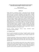
creep curve
display of the cumulative axial strain, expressed in %, of the test specimen as a function of the number
of loading cycles
Note 1 to entry:
—
—
—
Generally the following stages can be distinguished (see Figure 1):
stage 1: the (initial) part of the creep curve, where the slope of the curve decreases with increasing number of
loading cycles;
stage 2: the (middle) part of the creep curve, where the slope of the curve is quasi constant and can be
expressed by the creep rate fc (See key 5 of Figure 1). The exact turning point of the creep curve lies within
this stage;
stage 3: the (last) part of the creep curve, where the slope increases with increasing number of loading cycles.
Depending on the testing conditions and on the mixture, one or more stages may be absent.
Key
εn cumulative axial strain
n
1
2
3
4
5
number of loading cycles
stage 1
stage 2
stage 3
turning point
creep rate fc
Figure 1 — Example of creep curve
3.3
Creep rate
slope of axial strain of the test specimen after a given number of loading cycles
9
BS EN 12697-25:2016
EN 12697-25:2016 (E)
3.4
permanent deformation
cumulative axial deformation of the test specimen after a given number of loading cycles
4 Principle
This test method determines the resistance to permanent deformation of a cylindrical test specimen of
bituminous mixture by repeated load. The test specimens may be either prepared in the laboratory or
be cored from a pavement.
During the test, the change in height of the test specimen is measured at specified numbers of loading
cycles. From this, the cumulative axial strain εn of the test specimen is determined as a function of the
number of loading cycles. The results are represented in a creep curve as given in Figure 1. From this,
the creep characteristics of the test specimen are computed.
5 Equipment
5.1 Control and loading system
PC and software for controlling, reading and collecting necessary data. The control system shall
guarantee that during the test the physical parameter to be controlled (force) shows no overmodulation. The load cell shall have a capacity of at least 5000 N with a precision of ± 10 N. All
components shall be constructed out of hardened corrosion-resistant steel. The load cell should be able
to generate a block or haversine loading pulse with or without rest periods. Resonance frequencies of
the load cell, as mounted, shall be at least 10 times higher as the test frequency. Test frequencies in the
range of 0,5 Hz to 5 Hz are most often applied.
It is recommended that the control system should include a programmable function generator and a
control circuit with which the desired loading signal can be generated.
5.2 Displacement transducers
The deformation measurement system shall include two displacement transducers for measuring and
recording the cumulative axial deformation to the test specimen, by measuring the change of the upper
loading plate position during the test. The transducers shall have a tolerance of not more than 2 % for
the measuring range of 5 mm.
NOTE
Another number of suitable displacement transducers is possible, if proven, that inhomogeneous test
specimen deformation is levelled during the test.
5.3 Data registration equipment
A data-acquisition system shall be provided for controlling and collecting the signals from the load and
displacement transducers.
A system for graphical follow-up of the creep curve during testing is recommended.
5.4 Thermostatic chamber
A thermostatic chamber to maintain the temperature in the vicinity of the test specimen constant with a
tolerance of ± 0,5 °C .
It is recommended that a sufficiently large thermostatic chamber should be chosen, so that during the
test additional test specimens can be acclimatised inside the thermostatic chamber
10
BS EN 12697-25:2016
EN 12697-25:2016 (E)
5.5 Measuring instruments and accessories needed
5.5.1 Balance and other equipment required to determine the bulk density in accordance with
EN 12697-6.
5.5.2 Vernier callipers or other suitable apparatus to determine the test specimen dimensions in
accordance with EN 12697-29.
5.5.3 Angle meter (Protractor), which shall be capable of measuring to ± 0,5° for controlling the
angularity of the test specimen.
5.5.4 Thermometer of appropriate range, which shall be capable of measuring to ± 0,1 °C for
determining the temperature of the test specimen and the storage and test environment.
5.5.5 System for reducing the friction between test specimen and loading plate, see Clause 7.5.3
and/or 8.4.3.
6 Test specimen preparation
6.1 Number of test specimen
At least three test specimens shall be prepared for testing.
6.2 Test specimen compaction
For rolled asphalt the test shall be performed on
— test specimens prepared in the laboratory by gyratory compaction in accordance with
EN 12697-31;
— test specimens drilled from laboratory-prepared slab of asphalt by roller compactor in accordance
with EN 12697-33;
— test specimens prepared from drilled core test specimen taken from the road in accordance with
EN 12697-27;
— test specimens prepared in the laboratory by impact compactor in accordance with EN 12697-30.
NOTE 1
NOTE 2
The way of compaction has a considerable impact on the results.
For type testing: the compaction method is given in EN 13108–20.
6.3 Preparation of mastic asphalt test specimen
6.3.1 Accessories for test specimen preparation
— Cylindrical steel mould consisting of a ring (inner diameter (148 ± 5) mm, height ≥ 70 mm, steel
thickness ≥ 6 mm) and a bottom plate (diameter shall be 2 ( ± 1) mm smaller than the inner
diameter of the ring)
— Moulds of appropriate size so that cores can be taken at least 20 mm from the edges (in case of
6.3.3)
— Wooden tamper for levelling mastic asphalt
— Extruding device
11
BS EN 12697-25:2016
EN 12697-25:2016 (E)
— Release agent, (e.g. silicone grease or glycerine)
— Silicone paper disk with the same diameter ( ± 1 mm) as the bottom plate
— Core drill with an inner diameter of (148 ± 5) mm if cored test specimens are tested
6.3.2 Procedure for moulded test specimen
Heat the mould in a heating cabinet to a temperature of (150 ± 10) °C, apply release agent to the inner
surface, place it on top of the bottom plate and put the silicone paper disk into the mould.
Preheat the mixture without allowing fresh air circulation in an oven or a thermostatically regulated
heating mantle up to the reference temperature according EN 12697-35 or the temperature indicated
by the producer.
Revise national regulation about maximum temperatures. If the mixture is spreadable by that
temperature this can be applied instead of the temperature according to EN 12697-35.
Fill the homogenized asphalt mixture into the mould and tamp it in two layers and even the surface.
As soon as the test specimen has cooled to a temperature of between 18 °C and 28 °C remove it from the
mould and place it on a flat base.
6.3.3 Procedure for cored test specimen
Alternatively test specimens can be cored from site or from laboratory prepared slabs. The slab shall be
prepared in a height of at least 65 mm. Therefore, an adequate amount of mastic asphalt is filled into the
mould in two layers. When the slab is cooled down, the test specimens can be drilled with a core drill
with an inner diameter of (148 ± 5) mm. The cores shall be taken at least 20 mm from the edges of the
slab.
6.4 Preparation of test specimen surfaces
The ends of the test specimen shall be even and plan parallel, which is achieved by sawing both ends of
the test specimen. A diamond saw equipped with parallel blades is recommended. The ends shall be
parallel and perpendicular to the cylinder axis with an angle of less than 3° as measured by angle
meter/protractor. For a rough control of evenness brush the hand over the surface. If it feels even
without blemishes it shall be considered adequate, otherwise it shall be polished.
6.5 Determination of bulk density
The bulk density of the test specimen shall be measured in accordance with EN 12697-6.
6.6 Drying of the test specimen
Before testing, the test specimens shall be dried to constant mass in air at a relative air humidity of less
than 80 % at a temperature not more than 20 °C.
A test specimen shall be considered to be dry after at least 8 h drying time and when two weightings
performed minimum 4 h apart differ by less than 0,1 %.
6.7 Dimensions
The dimensions measured on the dry test specimen according to EN 12697-29.
12
BS EN 12697-25:2016
EN 12697-25:2016 (E)
7 Test method A — Uniaxial cyclic compression test with confinement
7.1 Principle
A cylindrical test specimen with a nominal diameter of 150 mm, maintained at elevated conditioning
temperature, is placed between two plan parallel loading platens. The lower platen shall have an area
that stretches at least 5 mm outside the test specimen. Both the bottom surface (the lower platen) and
the upper platen shall be made from hardened corrosion-resistant steel with a polished (flat and
smooth) surface. The weight of the upper load platen shall be considered as static (permanent) load if it
is not fixed to the test apparatus.
7.2 Test method A1 – block pulse loading
7.2.1 Upper loading plate
The upper platen has a diameter of 100 mm (by an inclination the pressure area against the test
specimen has a real diameter of 96 mm).
The dimensions of the upper platen shall be as follows: diameter (100 ± 0,5) mm, thickness (25 ±
0,5) mm and mass (1,55 ± 0,05) kg. The platen shall at the lower edge have an inclination as shown in
Figure 2, which gives a loading circular surface with a diameter of (96 ± 1) mm. The upper platen shall
be fitted with hemispherical self-aligning seating while the lower platen shall be fixed or held in place
by e.g. a spigot/slot system
NOTE
The inclination of the lower edge can also be rounded off.
Dimensions in millimetres
Figure 2 — Lower edge of the platen
7.2.2 Loading pulse
A schematic representation of the test device is given in Figure 3. There is no additional lateral
confinement pressure applied.
13
BS EN 12697-25:2016
EN 12697-25:2016 (E)
Figure 3 — Test apparatus
The test specimen is loaded by a rectangular (see Figure 4 and Figure 5) and periodical vertical stress
pulse, with a frequency of 0,5 Hz and a load of (100 ± 2) kPa.
NOTE
For this test method pneumatic test devices are applicable.
Key
1 strain, percent (%)
2 stress, kPa
3 preload, kPa
4
14
minimum stress, kPa
t
A
εn
time, s
strain at preload, percent (%)
cumulative axial strain, percent (%)
Figure 4 — Stress and strain curve for rectangular pulse loading
BS EN 12697-25:2016
EN 12697-25:2016 (E)
Key
1 load
2 duration of the pulse
x1 + x2 + x3 + x4 < 20 % of the whole pulse
Figure 5 — Loading curve for block pulse loading
7.3 Test method A2 – Haversine pulse loading
7.3.1 Upper loading plate
The upper platen has a diameter of 56,4 ± 0,2 mm (resulting in a loading area of 2500 mm2), thickness
(30 ± 0,5) mm and mass (0,59 ± 0,05) kg. A schematic representation of the upper platen is
represented in Figure 6.
15
BS EN 12697-25:2016
EN 12697-25:2016 (E)
Dimensions in millimetres
Key
1 steel sphere: allow adjustment of non-horizontal specimen surface
Figure 6 — Upper loading platen for test method A2
7.3.2 Loading pulse
The test specimen is subjected to a cyclic axial haversine-pulse pressure with rest time, as represented
in Figure 7. The loading pulse shall have a duration of 0,2 s with a rest period of 1,5 s between the
loading pulses (see Figure 7).
NOTE
16
For this test method hydraulic test devices are applicable.
BS EN 12697-25:2016
EN 12697-25:2016 (E)
Key
1 loading cycle
a
b
σ
t
loading pulse
rest period
stress, kPa
time, s
σ min
σ max
minimum pulse stress, 80 kPa
maximum pulse stress, 350 kPa
Figure 7 — Loading curve for haversine pulse loading
7.4 Test specimen
The test specimen shall have the following dimensions:
— the test specimen shall have a height of (60 ± 2) mm and a diameter of (148 ± 5) mm;
— the variations between the measurements according to EN 12697-29 shall not vary more than
1,0 mm for the height and 2,0 mm for the diameter.
In case of cored test specimens from the road and if the height of the individual test specimen is not
high enough, two test specimens may be put one on top of the other (but not more than two). The same
demands for evenness and plan-parallelism as for one test specimen shall be met for each of the test
specimens as for the two put together. Each of the test specimens shall have a height of at least 25 mm
(the two test specimens put together shall still have a height of (60 ± 2) mm). The test specimens are
put together without the use of any kind of substance.
Damage to the test specimen shall be avoided in all stages of sampling, transport and preparation
before testing. During transport and storage the slab and drilled core test specimen shall be fully
supported to prevent deformation or damage.
7.5 Conditioning
7.5.1 Storing conditions
The test specimens shall be stored for between 14 days and 42 days from the time of their manufacture
at a temperature not more than 20 °C. Test specimens shall be fully supported and not be stacked on
top of each other. Any damage shall be prevented.
17
BS EN 12697-25:2016
EN 12697-25:2016 (E)
NOTE 1
Storage time influences the mechanical properties of the test specimen.
For other applications of the test other than CE marking other conditioning times can be applied.
NOTE 2
For specific types of bituminous mixtures and if data are available, the strain for a given curing time
can be calculated with the procedure presented in Annex A (informative).
7.5.2 Cleaning and drying of test specimens
If necessary, the test specimens shall be cleaned by brushing or washing, as required.
If necessary, the test specimens shall be dried at a temperature not higher than 20 °C to constant mass.
7.5.3 Reduction of friction to loading platens
For reducing the friction between test specimen and loading plate, silicon oil with lubricants or a
mixture of glycerine and talcum can be used for coating of the plan-parallel areas of the test specimen.
7.5.4 Temperature conditioning
Test specimens shall be conditioned at the test temperature.
NOTE 1
NOTE 2
Test temperatures are generally between 30 °C and 50 °C.
It is possible to monitor the test specimen temperature using dummy test specimen.
7.6 Test procedure
7.6.1 Test temperature
The test temperature shall be kept constant to within ± 0,5 °C during the duration of the test.
7.6.2 Positioning of test specimen in test device
The test specimen shall be positioned well centred coaxially with the test axis between the two platens.
Two displacement transducers shall be positioned on the loading platen symmetrically in order to even
inhomogeneous axial test specimen deformation, one opposite to the other. The test shall not be started
until the test specimen has reached the specified test temperature within ± 0,5 °C.
7.6.3 Testing of test specimen
7.6.3.1 Loading conditions (Method A1)
A preload shall be applied. The accuracy on the preload control shall be ± 10 % or better.
NOTE 1
A typical value for tests on rolled asphalt according to method A1 is (72 ± 7) N (this corresponds to a
pre-stress of (10 ± 1) kPa on a test specimen with a diameter of the loading surface of 96 mm) which is applied for
(120 ± 6) s.
NOTE 2
The upper platen gives a constant static load, which however is not included in the cyclic load.
The registration of test specimen deformation shall be started directly after the preloading.
Immediately after the preloading time has ended, the periodic load shall be applied according to
EN 13108-20 and Clauses 7.2.2 of this standard.
For tests according to method A1 where a block loading is applied (see Clause 7.2.2), The loading time
for each pulse shall be (1 ± 0,05) s. The accuracy on the period load shall be ± 10 % or better. The
loading pulse can be seen in Figure 4 and Figure 5. Every rest period between the pulses shall be
(1 ± 0,05) s as well, meaning a frequency of approximately 0,5 Hz. Totally nmax = 3600 pulses shall be
applied (total time for the test about 2 h). A typical value for the axial load is (724 ± 14) N
18
BS EN 12697-25:2016
EN 12697-25:2016 (E)
(corresponding to a stress of (100 ± 2) kPa for a test specimen with a diameter of 96 mm) and a
minimum load during rest period of (15 ± 5) N.
7.6.3.2 Loading conditions (Method A2)
A preload shall be applied of (200 ± 5) N for (30 ± 5) s. Immediately after the preloading time has
ended, the periodic load shall be applied according to EN 13108-20 and Clauses 7.3.2 of this standard.
For tests according to method A2 where a haversine loading is applied (see Clause 7.3.2), the loading
time for each pulse shall be (0,2 ± 0,005) s with a rest period of (1,5 ± 0,05) s between the pulses. The
loading cycle can be seen in Figure 7. Totally nmax = 5000 loading cycles shall be applied. Typical values
for axial loads are
— (875 ± 5) N corresponding to a stress of (350 ± 5) kPa for the loading platen diameter of
(56,4 ± 0,2) mm for the maximum pulse load and
— (200 ± 5) N corresponding to a stress of (80 ± 5) kPa for the loading platen diameter of
(56,4 ± 0,2) mm for the minimum rest load.
7.6.4 Measurement of permanent deformation
The registration of test specimen deformation shall be started immediately with the beginning of the
first periodic loading pulse.
During the test regular measurements of the total permanent deformation shall be made. As a
minimum, readings shall be taken after the following loading cycles: 2, 4, 6, 8, 10, 20, 40, 60, 80, 100,
200, 300 etc. to the maximum number of cycles nmax applied. The total permanent deformation after a
loading cycle shall be measured during the last 0,2 s of the corresponding rest period as a mean by at
least 10 single measurements.
7.6.5 End of loading
The loading is stopped after nmax loading cycles. For test method A1, nmax = 3600 loading cycles are
applied. For test method A2, nmax = 5000 loading cycles are applied.
If the permanent deformation exceeds 5 mm the loading shall be stopped. The number of loading cycles
corresponding to 5 mm shall be reported.
7.7 Calculation and expression of results
7.7.1 Permanent deformation
7.7.1.1 Cumulative permanent deformation
The cumulative permanent deformation after n loading cycles applied, un,, shall be calculated in
millimetres (mm) from Formula (1)
u=
n h0 − hn
where
un
h0
(1)
is the cumulative permanent deformation of the test specimen after n loading cycles, in
millimetres (mm) to the nearest 0,01 mm;
is the mean vertical position of the upper loading plate as measured by displacement
transducers directly after end of preload of the test specimen, in millimetres (mm) to the
nearest 0,01 mm;
19
BS EN 12697-25:2016
EN 12697-25:2016 (E)
hn
is the mean vertical position of the upper loading plate as measured by displacement
transducers after n loading cycles, in millimetres (mm) to the nearest 0,01 mm.
7.7.1.2 Cumulative axial strain
The cumulative axial strain after n loading cycles, ε n shall be calculated in percent (%) to the nearest
0,01 % from Formula (2):
un
ti
ε n = 100
where
εn
(2)
is the cumulative axial strain of the test specimen after n loading cycles, in percent (%);
is the cumulative permanent deformation of the test specimen after n loading cycles, in
millimetres (mm) to the nearest 0,01 mm;
un
ti
is the initial thickness of the test specimen in mm.
If the cumulative axial strain exceeds 4 % a graph of total deformation versus number of loading cycles
shall be drawn, as it shall be seen as likely that the test specimen has been demolished (stage 3 of the
creep curve). The test report shall mention that the permanent deformation at the end of loading
exceeds 4 %. The number of loading cycles corresponding to 4 % shall be reported.
7.7.2
Creep rate and creep modulus
If requested calculate creep rate in stage 2 (compare Figure 1), f c , in µm/m/loading cycle, and creep
modulus, E n , in Megapascal, from the following formulae for a specified interval of loading cycles ( n1 ,
n2 ):
fc
=
where
ε n1 − ε n2
n1 − n2
fc
ε n1 ; ε n2
n1 ; n2
En =
where
En
εn
σ
σ
10 ε n
⋅10 000
(3)
is the creep rate, in µm/m/loading cycles to the nearest 0,01 µm/m/loading cycles;
is the cumulative axial strain of the test specimen after n1 , n2 loading cycles in
percent (%);
is the number of repetitive loading cycles.
(4)
is the creep modulus after n loading cycles, in Megapascal (MPa) to the nearest 0,1 MPa;
is the cumulative axial strain of the test specimen after n loading cycles, in percent (%) to
nearest 0,01%;
is the applied stress, in kilopascal (kPa);
If the cumulated axial strain exceeds 4 % and the drawn graph shows that the inflexion point has been
passed then the extrapolated inclination line with the least slope gives the creep rate.
20
BS EN 12697-25:2016
EN 12697-25:2016 (E)
7.8 Test report
7.8.1 General
The test report shall make reference to this European Standard and shall include information on the
test specimens and on the test results:
7.8.2 Information on the test specimens
For each set of test specimen the following information shall be provided in the test report:
a) type and origin of material tested;
b) test specimen identification number;
c) test specimen preparation method: laboratory made (refer to relevant EN standard) with indication
of compaction energy applied (if applicable) or cored from the road;
d) initial test specimen thickness t i in millimetre;
e) average diameter in millimetre;
f)
bulk density, in megagrams per cubic metre to the nearest 0,001 Mg/m3;
g) age of test specimens at test and storage conditions under which they were kept.
h) additional observations (including the number of discarded test specimens).
7.8.3 Information on test conditions
For each set of test specimens the following information shall be provided in the test report:
a) test temperature;
b) applied test method and pulse loading type (A1, block or A2, haversine), pulse loading time and rest
period time;
c) applied maximum pulse stress, in kilopascal (kPa);
d) applied minimum rest stress, in kilopascal (kPa);
e) maximum loading cycles applied (nmax)
7.8.4 Test results
For each test specimen, the following information shall be provided in the test report:
a) The cumulative permanent deformation after nmax loading cycles in millimetres (mm)
1) For test method A1, the cumulative deformation after n = 3600 loading cycles is reported;
2) For text method A2, the cumulative deformations after n = 2500 and n = 5000 are reported.
b) the cumulative axial strain after nmax loading cycles in percent (%);
1) For test method A1, the cumulative axial strain after n = 3600 loading cycles is reported;
21
BS EN 12697-25:2016
EN 12697-25:2016 (E)
2) For text method A2, the cumulative axial strain after n = 2500 and n = 5000 are reported.
c) creep characteristics, if requested;
d) the mean creep characteristics, if requested.
7.9 Precision
A precision study on test method A1 (block pulse loading) indicated the values of repeatability and
reproducibility (ref. VTI notat 24-2001 written by H. Hakim and L. Viman):
— repeatability r; approximately 17,3 %;
— reproducibility R; approximately 21,5 %.
8 Test method B — Triaxial cyclic compression test
8.1 Principle
This test method determines the resistance to permanent deformation of a cylindrical test specimen of
bituminous mixture. The test specimen is either prepared in the laboratory or cored from the road.
A cylindrical test specimen, maintained at elevated conditioning temperature, is placed between two
plan parallel loading platens. The test specimen is subjected to a static confining pressure, σ c , on which
a cyclic axial pressure σ A ( t ) is superposed.
It is possible to apply dynamic confining pressure. In this case, the following formulae has to be
adapted.
The cyclic axial pressure can be:
a) a haversinusoidal pressure σ A ( t ) , with amplitude σ V , as represented in Figure 8:
σ A ( t=) σ c + σ V ⋅ (1 + sin ( 2π ⋅ f ⋅ t − π / 2) )
(5)
Rest periods can be applied ( σ rest = σ c ). In this case, the loading signal is characterized by the duration
of loading pulse and of the rest period t load / t rest :
where
σ A (t )
σc
σV
f
t load
t rest
t
NOTE 1
t load .
22
is the cyclic axial pressure as a function of time, in kilopascal (kPa);
is the confining stress (all around the test specimen), kilopascal (kPa);
is the amplitude of the haversinusoidal pressure, in kilopascal (kPa);
is the frequency of a loading pulse, in hertz (Hz);
duration of the loading pulse;
duration of the rest period between 2 loading pulses;
is the time, in seconds (s).
For haversinusoidal signal the loading frequency corresponds to the loading pulse duration: f = 1/
BS EN 12697-25:2016
EN 12697-25:2016 (E)
If a confining stress of less than 25 kPa is applied (e.g. for simulating unconfined test specimens) a
minimum axial load of 25 kPa should be applied in order to avoid the lifting of the loading platen from
the test specimen surface during the test.
b) a block-pulse pressure σ A ( t ) , with height σ B , as represented in Figure 9. The resulting total
pressure is:
σ A (t ) = σ c + σ B (t )
where
σ A (t )
σ A (t )
σc
σB
(5.a)
is the cyclic axial pressure as a function of time, in kilopascal (kPa);
is equal to σ B during pulse period T1 and is equal to σ c during rest period T0
is the confining stress, in kilopascal (kPa)
is the height of block pulse, in kilopascal (kPa)
In both cases a small dead stress of maximum 0,02 ⋅(2 ⋅ σ V + σ c ) in the case of haversinusoidal loading
and 0,02 ⋅ (σ B + σ c ) (for block-pulse loading) is allowed.
Key
σA
σc
σV
total axial pressure, kP
at
time, s
amplitude of the haversinusoidal pressure
t rest
duration of the rest period
confining pressure
t load
duration of the loading pulse
Figure 8 — Representation of the pressures exerted on the test specimen in case of
haversinusoidal cyclic loading with and without rest periods
23