Development of Laser Beam Diffraction Technique for Determination of Thermal Expansion Coefficient of Polymeric Thin Films
Bạn đang xem bản rút gọn của tài liệu. Xem và tải ngay bản đầy đủ của tài liệu tại đây (748.32 KB, 14 trang )
VNU Journal of Science: Mathematics – Physics, Vol. 31, No. 2 (2015) 21-27
Development of Laser Beam Diffraction
Technique for Determination of Thermal Expansion
Coefficient of Polymeric Thin Films
Nguyen Van Thuan1, Tran Vinh Son2, Tran Quang Trung2,
Tran Thi Thao1, Nguyen Nang Dinh1,*
1
2
VNU University of Engineering and Technology, 144 Xuan Thuy, Cau Giay, Hanoi, Vietnam
University of Natural Science, VNU Ho Chi Minh City, 227 Nguyen Van Cu, District 5, Ho Chi Minh City
Received 04 March 2015
Revised 15 April 2015; Accepted 13 May 2015
Abstract: Laser beam diffraction by a patterned surface has been investigated theoretically and
experimentally for the determination of the thermal expansion coefficient (α) of polymeric
materials. By tracking the deviation of the first order diffraction mode from surface-patterned
polymers, expansion coefficients in a range 10-7 to 10-4 K-1 can be measured by temperature
changes less than 100 oC. A set-up of laser diffraction (SLD) was made, using a He-Ne laser (λ =
632.8 nm) and thin film casting technique. The results of measurements on the SLD system for
polymers like PVK polycarbonate, PDMS, organic complex (chitosan) and conducting polymer
(P3HT) showed that SLD technique can be applied to determine thermal expansion coefficients of
different polymeric materials with a considerably small volume. Especially, the fact that α of
P3HT-composite films was found to be much lower than that of the pure P3HT suggests a
potential application of polymeric composites for organic devices working at elevated temperature,
for organic solar cells (OSC) in particular.
Keywords: Laser beam diffraction; thermal expansion; diffraction grating; polymer.
1. Introduction∗
Conducting polymers and polymer-based devices have been increasingly studied due to their
potential application in optoelectronics, such as field emission transistors (FETs), organic light
emitting diodes (OLED), organic solar cells (OSC), etc [1-4]. Comparing with inorganic devices, the
performance efficiency and service durability of organic devices until now are considerably low. In
OSC this limitation is usually attributed to the strong decay of the excitons which are generated in the
donors/acceptors junctions owing to the illumination of solar radiation. The excitons decay can be
_______
∗
Corresponding author. Tel.: 84-904158300
Email:
21
22
N.V. Thuan et al. / VNU Journal of Science: Mathematics – Physics, Vol. 31, No. 2 (2015) 21-27
diminished by the creation of either appropriate heterojunctions or nanocomposite layers. This results
in the charge separation, i.e. generated electrons and holes move in opposite directions, and
consequently the luminous quenching occurs [5]. Thus, by embedding inorganic nanocrystalline
oxides into polymer matrices one can enhance the efficiency and service duration of the devices. The
embedded oxides can substantially influence both the electrical, and optical properties of the polymer,
for instance, nanocrystalline TiO2 (nc-TiO2) particles in poly(3-hexylthiophene) (P3HT), abbreviated to
P3HT + nc-TiO2 composite thin films were studied as a photoactive material [6]. It is very important
to improve the thermal stability of the device performance under operating conditions. For OSC, the
thermal stability is strongly dependent on the thermal expansion of the polymeric active layer.
However, until now as so far, from references we have not found yet the data of the thermal expansion
coefficient (α) of the conjugate polymers like poly[2-methoxy-5-(2'-ethyl-hexyloxy)-1,4phenylenevinylene] (abbreviated to MEH-PPV) and (P3HT). Thus to determine α of these conjugate
polymers is necessary for characterizing the stability of the device performance.
Methods for measuring thermal expansion coefficient (α) of materials often rely on electromechanical techniques such as capacitance changes [7], strain gauges and push rods [8]. Measuring
displacement with a mechanical device introduces difficulties with regard to calibration and thermal
isolation of the sample from the push rod and sensors. To avoid these difficulties, optical techniques
based on the Michelson interferometry with a resolution on the order of the wavelength are commonly
used [9-12]. On the other hand, the propagation of laser beams in media with varying temperature
introduces phase shifts which need to be calibrated and corrected.
In this paper, we demonstrate a non-contact optical method to achieve high-accuracy thermal
expansion measurement using a single laser beam. Contrary to interferometric techniques, the optical
technique is less affected by the temperature gradient of air ambience. An advantage over
conventional methods is that, by using non-contact optical method one can determine α for very thin
samples, consequently a small volume of the materials investigated is required.
2. Determination of thermal expansion coefficient
2.1. Principles of measurement technique
A Gaussian laser beam with a width w and wavelength
radiates to a diffraction grating with a
slit separation Г. Suggest that angles
and
represent, respectively the incident and diffracted
angles relative to the normal of the grating. Both the incident and diffracted beams lie in the plane
normal to the ruling of the grating. According to Bragg’s condition for diffraction, there is:
mλ = Г(sinθm - sinθi )
(m is order, Г is split separation)
(1)
If slit separation of the grating Г changes as a result of thermal expansion (or stress), the diffracted
angle θm is expected to change accordingly. Arcording to Eq. 1, it is possible to obtain the thermal
expansion coefficient of the grating by measuring the location of diffraction beam after increased
temperature. Assuming the grating is made of a material with a linear expansion, we can calculate the
linear expansion coefficient (α), as follows.
Г(T) = Г0 (1 + α.∆T)
(2)
N.V. Thuan et al. / VNU Journal of Science: Mathematics – Physics, Vol. 31, No. 2 (2015) 21-27
23
where
is slit separation of the grating at room temperature (RT); Г(T) - slit separation of the
grating at the measuring temperature and ∆T = T - TRT.
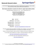
Figure 1 shows a set-up of thermal expansion measurements by laser diffraction. A red He-Ne
laser beam (632.8 nm) was collimated to a width of 3 mm (FWHM) and focused to the sample. The
sample was heated from room temperature up to 200 oC by a heater controlled via computer. Using a
thermocouple to feedback the control unit, temperature is stabilized to within 0.2 oC. A silicon CCD
camera with 720 pixel in x and 576 pixels in z, for a resolution of 6.65 µm per pixel, was positioned at
the minimum waist of the focused diffracted beam. The detector can be moved to capture various
diffraction orders (m = 1, 2, 3,...). The distance from sample to camera (f) can be adjusted from 10
to 500 mm, howerver in our experiments, the most suitable value of f was fixed at 150, 250 or
300 mm for polymeric materials like chitosan, PDMS, PVK and P3HT.
At the different temperature of sample, the beam location on the camera is analyzed by computer
in real time by mean of a Gaussian profile fitting algorithm. From measured data, one can determine
the thermal expansion coefficient of the samples.
Fig. 1. Schematic of the linear thermal expansion coefficient measurement linear thermal expansion coefficient
using laser beam diffraction.
The samples studied included various types of already patterned surfaces using casting or
stampling technique. Among prepared samples, polymer grating films were made by casting polymer
solutions over diffraction grating preformed. The ruled grating has a slit separation Г = 1600 ± 100
nm. Polydimethylsiloxane (PDMS), conducting polymer P3HT and organic complex like chitosan
with a thickness lees than 100 µm were patterned by the casting method, whereas other kind of
polymers like polycarbonate (PVK), poly(vinyl chloride) (PVC), etc. with thickness over 250 µm were
prepared by applying pressure on a flat substrate lying in contact with a preformed grating.
From equation (1) and (2) one can set-up a relationship of thermal expansion coefficient (α), the
diffraction angle and sample temperature in case θi = 0:
α=
1
sin θ
− 1
∆T sin (θ ± ∆θ )
(3)
where ∆θ is angular resolution of diffraction beam at different temperature via the resolution of the
beam position calculating from pixel position on the camera:
24
N.V. Thuan et al. / VNU Journal of Science: Mathematics – Physics, Vol. 31, No. 2 (2015) 21-27
∆θ =
D × ∆x
(in radian)
f
(4)
where D is a pixel size along x-axis. In our experiments D is fixed at 6614 nm; ∆x is a pixel-shift
(the multiple number of D) and and f - distance between sample and camera. Thus from experimental
data obtained for ∆x one, can determine ∆θ by Eq. 4, consequently thermal expansioncoefficient (α)
by Eq. 3.
2.2. Determination of thermal expansion coefficient of some polymers
From thermal expansion coefficient references the thermal expansion coefficient some kinds of
popular materials was charcterized and reported. For instance, for used for polycarbonate α = 65 to
70 × 10-6 K-1 [9], for PDMS α = 300 to 320 × 10-6 K-1 [10] and for chitosan α = - 2.5 × 10⁻³ K-1 [11]. In
our experiments we also used these materials for the determination of α by the SLD technique,
consequently to compare its accuracy with the one of the traditional methods. Further, by the same
SLD technique we carried-out measurements of thermal expansion coefficient of two types of
samples: pure conjugate polymers P3HT and composite of P3HT and nc-TiO2.
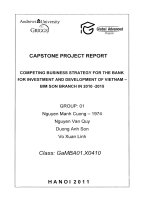
a. Polycarbonate.
This is a popular polymer that is used for the thermal isolation or optical compact disk. By melting
polycarbonate at 160 oC then cast on diffraction grating, we can obtain the film of polycarbonate. The
set-up parameters in measurement process are f = 300 mm, first order diffraction angle 24.5o and ∆T =
75o C. The difracted beam location on the camera is analyzed by computer in real time by mean of a
Gaussian profile fitting algorithm (Fig. 2), and the pixel-shift was of ∆x = 99. Using Eq. 4 with data of
D (6614 nm or 6.614×10⁻³ mm) and (f = 300 mm), ∆θ was found to be ca. 0.002 (rad) or 0.126o. Then
the thermal expansion coefficient calculated from Eq. 3 was determined at ~ 64 × 10-6 K-1. This result
is quite close to the value reported in [9]. In a repeated experiment with ∆T = 67o C, the received α
was 70 × 10-6 K-1 which is similiar to the one that was reported in [13]. A neglegible difference in the
values of α that were determined by either the traditional [9, 13] or SLD techniques reflects the
different errors of each measuring method. Thus the thermal expansion coeeficient of polycarbonate is
approximately equal to (67±3) 10-6 K-1.
Fig. 2. Pixel shift of PVK-polycarbonate (a) and time-temperature dependence of heating (b).
N.V. Thuan et al. / VNU Journal of Science: Mathematics – Physics, Vol. 31, No. 2 (2015) 21-27
25
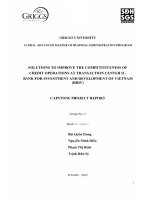
b. Polydimethylsiloxane (PDMS)
The thermal expansion of PDMS is higher than of polycarbonate. The thin PDMS grating was
performed by casting method on the reference ruled glass grating with Г0 = 1600 nm. The set-up
parameters in measurement process are f = 150 mm, first order diffraction angle 24.5o and ∆T =
72o C. The pixel-shift was of 234, consequently the thermal expansion coefficient was found to
-1
be ca. 320 × 10-6 K that was analyzed in real time by mean of a Gaussian profile fitting
algorithm (Fig. 3). In a repeated experiment with ∆T = 70o C and f = 250 mm, the obtained result
-1
was of almost the same value as 320 × 10-6 K . These results are close to the value reported in
[13].
Fig. 3. Pixel shift of PDMS (a) and time-temperature dependence of heating (b).
Fig. 4. Pixel shift of chitosan (a) and time-temperature dependence of heating (b).
26
N.V. Thuan et al. / VNU Journal of Science: Mathematics – Physics, Vol. 31, No. 2 (2015) 21-27
c. Chitosan
Chitosan, a derivative of chitin, a biopolymer found in insects and crustacean shells that are
applied on water filter, anti-bacteria and medicine. Chitosan have the negative thermal expansion
coefficient. A solution of 1% chitosan in water and acetic acid was dropped on the surface of grating
with density 625 grooves/mm (Г0 = 1600 nm), and then heated at 50-60oC to evaporate the solvent
slowly. Then, the dried film was peeled off and used as a self-supported sample. The set-up
parameters in measurement process are f = 250 mm, first order diffraction angle 24.5o and ∆T= 9o C
and the thermal expansion coefficient is calculated about -1.6 × 10⁻³ K-1 (Fig. 4). In the repeated
experiments with ∆T= 10o C and f = 250 mm, the received result is -1.4 × 10⁻³ K-1. The absolute values
are not much larger than -2.5 × 10⁻³ K-1 as reported in [11] and this difference is due to the derivative
technique.
d. P3HT
For measurering the thermal expansion coefficient of the pure P3HT and PTC, a solution of 10 mg
of P3HT and PTC in chloroform was dropped on the surface of glass grating with density 625
grooves/mm (Г0 = 1600 nm), and then slowly heated at 70-80oC in vacuum to evaporate the solvent.
The set-up parameters in measurement process are f = 250 mm, first order diffraction angle 24.5o
and ∆T = 27o C and the thermal expansion coefficient was calculated about 71 × 10-6 K-1 for P3HT and
8.5 × 10⁻⁶ K-1 for the PTC composite. In the repeated experiments with ∆T= 10o C and f = 250mm, the
obtained results for P3HT and PTC samples were of 76 × 10-6 K-1 and 9.1 × 10⁻⁶ K-1, respectively (Fig.
5). This demonstrates that both the P3HT and PTC composite have positive thermal expansion
coefficients. Moreover, the polymeric composite film possesses much smaller thermal expansion
coefficient than that of the pure polymer. As seen in [14], changing of the thermal expansion of
polymer composites was successfully carried-out by blending with a negative thermal expansion
material. Table 1 lists values of the thermal expansion coefficient of the measured polymers at room
temperature.
Fig.5. Pixel shift of P3HT (a) and time-temperature dependence of heating (b).
N.V. Thuan et al. / VNU Journal of Science: Mathematics – Physics, Vol. 31, No. 2 (2015) 21-27
27
Table.1. Thermal expansion coefficient of some polymers
Polymers
Polycarbonate
PDMS
Chitosan
P3HT
P3HT+nc-TiO2
α (K-1)
(64 − 70) × 10-6
(310 − 320) × 10-6
- (1.4 − 1.6) × 10-3
(71 - 76) × 10-6
(8.5 to 9.1) × 10-6
α, K-1 (from Ref.)
(65 − 70) × 10-6 [9]
(300 − 320) × 10-6 [10]
- 2.5 × 10⁻³ [11]
Unknown
Unknown
3. Conclusion
By using a He-Ne laser (λ = 632.8 nm) and casting polymer technique, a set-up of laser diffraction
(SLD) was made for measurements of thermal expansion coefficient of polymers. Measurement
results obtained on the SLD for polymers like PVK, PDMS, chitosan, conducting polymer P3HT and
composite of P3HT+nc-TiO2 allowed to apply SLD technique for determining thermal expansion
coefficients of different polymeric materials with a considerably small volume. The fact that the
thermal expansion coefficient of P3HT composite films is much lower than that of the pure P3HT
suggests a useful application of polymeric composites for producing organic devices, especially
organic solar cells working at elevated temperatures.
Acknowledgements
This research is funded by Vietnam National Foundation for Science and Technology
(NAFOSTED) under grant number 103.02-2013.39.
References
[1] B. D. Malhotra, Handbook of Polymers in Electronics, Rapra Technology Ltd., Shawbury, Shrewsbury,
Shropshire, SY4 4NR, UK, 2002.
[2] J. S. Salafsky, Phys. Rev. B 59 (1999) 10885.
[3] V. M. Burlakov, K. Kawata, H. E. Assender, G. A. D. Briggs, A. Ruseckas, I. D. W. Samuel, Phys. Rev. B 72
(2005), 075206.
[4] A. Petrella, M. Tamborra, P. D. Cozzoli, M. L. Curri, M. Striccoli, P. Cosma, G. M. Farinola, F. Babudri, F. Naso, A.
Agostiano, Thin Solid Films 451/452 (2004) 64.
[5] S. Bhattacharyya, A. Patra, Bull. Mater. Sci. 35 (2012) 719.
[6] Tran Thi Thao, Do Ngoc Chung, Nguyen Nang Dinh, Vo-Van Truong, Comm. in Phys. 24 (2014) No. 3S1, 22-28.
[7] R. Scholl, B. W. Liby, Manhattan College, Riverdale, NY 2009 The Physics Teacher, Vol. 47.
[8] H. Watanabe, N. Yamada, M. Okaji, Inter J. of Thermophysics 25 (2004) 221.
[9] />[10] W. W. Tooley, S. Feghhi, S. J. Han, J. Wang, N. J. Sniadecki, J. Micromech Microeng (IOP publishing) 21
(2011) 054013.
[11] P. A. Do, M. Touaibia, A. Haché, App. Optics, 52 (2013) No. 24, 5979.
[12] />[13] www.plasticsintl.com/datasheets/Polycarbonate.pdf
[14] A. Chandra, W. H. Meyer, A. Best, A. Hanewald, G. Wegner, Macromol. Mater. & Eng. 292 (2007) No. 3, 295.
VNU Journal of Science: Mathematics – Physics, Vol. 31, No. 2 (2015) 21-27
Development of Laser Beam Diffraction
Technique for Determination of Thermal Expansion
Coefficient of Polymeric Thin Films
Nguyen Van Thuan1, Tran Vinh Son2, Tran Quang Trung2,
Tran Thi Thao1, Nguyen Nang Dinh1,*
1
2
VNU University of Engineering and Technology, 144 Xuan Thuy, Cau Giay, Hanoi, Vietnam
University of Natural Science, VNU Ho Chi Minh City, 227 Nguyen Van Cu, District 5, Ho Chi Minh City
Received 04 March 2015
Revised 15 April 2015; Accepted 13 May 2015
Abstract: Laser beam diffraction by a patterned surface has been investigated theoretically and
experimentally for the determination of the thermal expansion coefficient (α) of polymeric
materials. By tracking the deviation of the first order diffraction mode from surface-patterned
polymers, expansion coefficients in a range 10-7 to 10-4 K-1 can be measured by temperature
changes less than 100 oC. A set-up of laser diffraction (SLD) was made, using a He-Ne laser (λ =
632.8 nm) and thin film casting technique. The results of measurements on the SLD system for
polymers like PVK polycarbonate, PDMS, organic complex (chitosan) and conducting polymer
(P3HT) showed that SLD technique can be applied to determine thermal expansion coefficients of
different polymeric materials with a considerably small volume. Especially, the fact that α of
P3HT-composite films was found to be much lower than that of the pure P3HT suggests a
potential application of polymeric composites for organic devices working at elevated temperature,
for organic solar cells (OSC) in particular.
Keywords: Laser beam diffraction; thermal expansion; diffraction grating; polymer.
1. Introduction∗
Conducting polymers and polymer-based devices have been increasingly studied due to their
potential application in optoelectronics, such as field emission transistors (FETs), organic light
emitting diodes (OLED), organic solar cells (OSC), etc [1-4]. Comparing with inorganic devices, the
performance efficiency and service durability of organic devices until now are considerably low. In
OSC this limitation is usually attributed to the strong decay of the excitons which are generated in the
donors/acceptors junctions owing to the illumination of solar radiation. The excitons decay can be
_______
∗
Corresponding author. Tel.: 84-904158300
Email:
21
22
N.V. Thuan et al. / VNU Journal of Science: Mathematics – Physics, Vol. 31, No. 2 (2015) 21-27
diminished by the creation of either appropriate heterojunctions or nanocomposite layers. This results
in the charge separation, i.e. generated electrons and holes move in opposite directions, and
consequently the luminous quenching occurs [5]. Thus, by embedding inorganic nanocrystalline
oxides into polymer matrices one can enhance the efficiency and service duration of the devices. The
embedded oxides can substantially influence both the electrical, and optical properties of the polymer,
for instance, nanocrystalline TiO2 (nc-TiO2) particles in poly(3-hexylthiophene) (P3HT), abbreviated to
P3HT + nc-TiO2 composite thin films were studied as a photoactive material [6]. It is very important
to improve the thermal stability of the device performance under operating conditions. For OSC, the
thermal stability is strongly dependent on the thermal expansion of the polymeric active layer.
However, until now as so far, from references we have not found yet the data of the thermal expansion
coefficient (α) of the conjugate polymers like poly[2-methoxy-5-(2'-ethyl-hexyloxy)-1,4phenylenevinylene] (abbreviated to MEH-PPV) and (P3HT). Thus to determine α of these conjugate
polymers is necessary for characterizing the stability of the device performance.
Methods for measuring thermal expansion coefficient (α) of materials often rely on electromechanical techniques such as capacitance changes [7], strain gauges and push rods [8]. Measuring
displacement with a mechanical device introduces difficulties with regard to calibration and thermal
isolation of the sample from the push rod and sensors. To avoid these difficulties, optical techniques
based on the Michelson interferometry with a resolution on the order of the wavelength are commonly
used [9-12]. On the other hand, the propagation of laser beams in media with varying temperature
introduces phase shifts which need to be calibrated and corrected.
In this paper, we demonstrate a non-contact optical method to achieve high-accuracy thermal
expansion measurement using a single laser beam. Contrary to interferometric techniques, the optical
technique is less affected by the temperature gradient of air ambience. An advantage over
conventional methods is that, by using non-contact optical method one can determine α for very thin
samples, consequently a small volume of the materials investigated is required.
2. Determination of thermal expansion coefficient
2.1. Principles of measurement technique
A Gaussian laser beam with a width w and wavelength
radiates to a diffraction grating with a
slit separation Г. Suggest that angles
and
represent, respectively the incident and diffracted
angles relative to the normal of the grating. Both the incident and diffracted beams lie in the plane
normal to the ruling of the grating. According to Bragg’s condition for diffraction, there is:
mλ = Г(sinθm - sinθi )
(m is order, Г is split separation)
(1)
If slit separation of the grating Г changes as a result of thermal expansion (or stress), the diffracted
angle θm is expected to change accordingly. Arcording to Eq. 1, it is possible to obtain the thermal
expansion coefficient of the grating by measuring the location of diffraction beam after increased
temperature. Assuming the grating is made of a material with a linear expansion, we can calculate the
linear expansion coefficient (α), as follows.
Г(T) = Г0 (1 + α.∆T)
(2)
N.V. Thuan et al. / VNU Journal of Science: Mathematics – Physics, Vol. 31, No. 2 (2015) 21-27
23
where
is slit separation of the grating at room temperature (RT); Г(T) - slit separation of the
grating at the measuring temperature and ∆T = T - TRT.
Figure 1 shows a set-up of thermal expansion measurements by laser diffraction. A red He-Ne
laser beam (632.8 nm) was collimated to a width of 3 mm (FWHM) and focused to the sample. The
sample was heated from room temperature up to 200 oC by a heater controlled via computer. Using a
thermocouple to feedback the control unit, temperature is stabilized to within 0.2 oC. A silicon CCD
camera with 720 pixel in x and 576 pixels in z, for a resolution of 6.65 µm per pixel, was positioned at
the minimum waist of the focused diffracted beam. The detector can be moved to capture various
diffraction orders (m = 1, 2, 3,...). The distance from sample to camera (f) can be adjusted from 10
to 500 mm, howerver in our experiments, the most suitable value of f was fixed at 150, 250 or
300 mm for polymeric materials like chitosan, PDMS, PVK and P3HT.
At the different temperature of sample, the beam location on the camera is analyzed by computer
in real time by mean of a Gaussian profile fitting algorithm. From measured data, one can determine
the thermal expansion coefficient of the samples.
Fig. 1. Schematic of the linear thermal expansion coefficient measurement linear thermal expansion coefficient
using laser beam diffraction.
The samples studied included various types of already patterned surfaces using casting or
stampling technique. Among prepared samples, polymer grating films were made by casting polymer
solutions over diffraction grating preformed. The ruled grating has a slit separation Г = 1600 ± 100
nm. Polydimethylsiloxane (PDMS), conducting polymer P3HT and organic complex like chitosan
with a thickness lees than 100 µm were patterned by the casting method, whereas other kind of
polymers like polycarbonate (PVK), poly(vinyl chloride) (PVC), etc. with thickness over 250 µm were
prepared by applying pressure on a flat substrate lying in contact with a preformed grating.
From equation (1) and (2) one can set-up a relationship of thermal expansion coefficient (α), the
diffraction angle and sample temperature in case θi = 0:
α=
1
sin θ
− 1
∆T sin (θ ± ∆θ )
(3)
where ∆θ is angular resolution of diffraction beam at different temperature via the resolution of the
beam position calculating from pixel position on the camera:
24
N.V. Thuan et al. / VNU Journal of Science: Mathematics – Physics, Vol. 31, No. 2 (2015) 21-27
∆θ =
D × ∆x
(in radian)
f
(4)
where D is a pixel size along x-axis. In our experiments D is fixed at 6614 nm; ∆x is a pixel-shift
(the multiple number of D) and and f - distance between sample and camera. Thus from experimental
data obtained for ∆x one, can determine ∆θ by Eq. 4, consequently thermal expansioncoefficient (α)
by Eq. 3.
2.2. Determination of thermal expansion coefficient of some polymers
From thermal expansion coefficient references the thermal expansion coefficient some kinds of
popular materials was charcterized and reported. For instance, for used for polycarbonate α = 65 to
70 × 10-6 K-1 [9], for PDMS α = 300 to 320 × 10-6 K-1 [10] and for chitosan α = - 2.5 × 10⁻³ K-1 [11]. In
our experiments we also used these materials for the determination of α by the SLD technique,
consequently to compare its accuracy with the one of the traditional methods. Further, by the same
SLD technique we carried-out measurements of thermal expansion coefficient of two types of
samples: pure conjugate polymers P3HT and composite of P3HT and nc-TiO2.
a. Polycarbonate.
This is a popular polymer that is used for the thermal isolation or optical compact disk. By melting
polycarbonate at 160 oC then cast on diffraction grating, we can obtain the film of polycarbonate. The
set-up parameters in measurement process are f = 300 mm, first order diffraction angle 24.5o and ∆T =
75o C. The difracted beam location on the camera is analyzed by computer in real time by mean of a
Gaussian profile fitting algorithm (Fig. 2), and the pixel-shift was of ∆x = 99. Using Eq. 4 with data of
D (6614 nm or 6.614×10⁻³ mm) and (f = 300 mm), ∆θ was found to be ca. 0.002 (rad) or 0.126o. Then
the thermal expansion coefficient calculated from Eq. 3 was determined at ~ 64 × 10-6 K-1. This result
is quite close to the value reported in [9]. In a repeated experiment with ∆T = 67o C, the received α
was 70 × 10-6 K-1 which is similiar to the one that was reported in [13]. A neglegible difference in the
values of α that were determined by either the traditional [9, 13] or SLD techniques reflects the
different errors of each measuring method. Thus the thermal expansion coeeficient of polycarbonate is
approximately equal to (67±3) 10-6 K-1.
Fig. 2. Pixel shift of PVK-polycarbonate (a) and time-temperature dependence of heating (b).
N.V. Thuan et al. / VNU Journal of Science: Mathematics – Physics, Vol. 31, No. 2 (2015) 21-27
25
b. Polydimethylsiloxane (PDMS)
The thermal expansion of PDMS is higher than of polycarbonate. The thin PDMS grating was
performed by casting method on the reference ruled glass grating with Г0 = 1600 nm. The set-up
parameters in measurement process are f = 150 mm, first order diffraction angle 24.5o and ∆T =
72o C. The pixel-shift was of 234, consequently the thermal expansion coefficient was found to
-1
be ca. 320 × 10-6 K that was analyzed in real time by mean of a Gaussian profile fitting
algorithm (Fig. 3). In a repeated experiment with ∆T = 70o C and f = 250 mm, the obtained result
-1
was of almost the same value as 320 × 10-6 K . These results are close to the value reported in
[13].
Fig. 3. Pixel shift of PDMS (a) and time-temperature dependence of heating (b).
Fig. 4. Pixel shift of chitosan (a) and time-temperature dependence of heating (b).
26
N.V. Thuan et al. / VNU Journal of Science: Mathematics – Physics, Vol. 31, No. 2 (2015) 21-27
c. Chitosan
Chitosan, a derivative of chitin, a biopolymer found in insects and crustacean shells that are
applied on water filter, anti-bacteria and medicine. Chitosan have the negative thermal expansion
coefficient. A solution of 1% chitosan in water and acetic acid was dropped on the surface of grating
with density 625 grooves/mm (Г0 = 1600 nm), and then heated at 50-60oC to evaporate the solvent
slowly. Then, the dried film was peeled off and used as a self-supported sample. The set-up
parameters in measurement process are f = 250 mm, first order diffraction angle 24.5o and ∆T= 9o C
and the thermal expansion coefficient is calculated about -1.6 × 10⁻³ K-1 (Fig. 4). In the repeated
experiments with ∆T= 10o C and f = 250 mm, the received result is -1.4 × 10⁻³ K-1. The absolute values
are not much larger than -2.5 × 10⁻³ K-1 as reported in [11] and this difference is due to the derivative
technique.
d. P3HT
For measurering the thermal expansion coefficient of the pure P3HT and PTC, a solution of 10 mg
of P3HT and PTC in chloroform was dropped on the surface of glass grating with density 625
grooves/mm (Г0 = 1600 nm), and then slowly heated at 70-80oC in vacuum to evaporate the solvent.
The set-up parameters in measurement process are f = 250 mm, first order diffraction angle 24.5o
and ∆T = 27o C and the thermal expansion coefficient was calculated about 71 × 10-6 K-1 for P3HT and
8.5 × 10⁻⁶ K-1 for the PTC composite. In the repeated experiments with ∆T= 10o C and f = 250mm, the
obtained results for P3HT and PTC samples were of 76 × 10-6 K-1 and 9.1 × 10⁻⁶ K-1, respectively (Fig.
5). This demonstrates that both the P3HT and PTC composite have positive thermal expansion
coefficients. Moreover, the polymeric composite film possesses much smaller thermal expansion
coefficient than that of the pure polymer. As seen in [14], changing of the thermal expansion of
polymer composites was successfully carried-out by blending with a negative thermal expansion
material. Table 1 lists values of the thermal expansion coefficient of the measured polymers at room
temperature.
Fig.5. Pixel shift of P3HT (a) and time-temperature dependence of heating (b).
N.V. Thuan et al. / VNU Journal of Science: Mathematics – Physics, Vol. 31, No. 2 (2015) 21-27
27
Table.1. Thermal expansion coefficient of some polymers
Polymers
Polycarbonate
PDMS
Chitosan
P3HT
P3HT+nc-TiO2
α (K-1)
(64 − 70) × 10-6
(310 − 320) × 10-6
- (1.4 − 1.6) × 10-3
(71 - 76) × 10-6
(8.5 to 9.1) × 10-6
α, K-1 (from Ref.)
(65 − 70) × 10-6 [9]
(300 − 320) × 10-6 [10]
- 2.5 × 10⁻³ [11]
Unknown
Unknown
3. Conclusion
By using a He-Ne laser (λ = 632.8 nm) and casting polymer technique, a set-up of laser diffraction
(SLD) was made for measurements of thermal expansion coefficient of polymers. Measurement
results obtained on the SLD for polymers like PVK, PDMS, chitosan, conducting polymer P3HT and
composite of P3HT+nc-TiO2 allowed to apply SLD technique for determining thermal expansion
coefficients of different polymeric materials with a considerably small volume. The fact that the
thermal expansion coefficient of P3HT composite films is much lower than that of the pure P3HT
suggests a useful application of polymeric composites for producing organic devices, especially
organic solar cells working at elevated temperatures.
Acknowledgements
This research is funded by Vietnam National Foundation for Science and Technology
(NAFOSTED) under grant number 103.02-2013.39.
References
[1] B. D. Malhotra, Handbook of Polymers in Electronics, Rapra Technology Ltd., Shawbury, Shrewsbury,
Shropshire, SY4 4NR, UK, 2002.
[2] J. S. Salafsky, Phys. Rev. B 59 (1999) 10885.
[3] V. M. Burlakov, K. Kawata, H. E. Assender, G. A. D. Briggs, A. Ruseckas, I. D. W. Samuel, Phys. Rev. B 72
(2005), 075206.
[4] A. Petrella, M. Tamborra, P. D. Cozzoli, M. L. Curri, M. Striccoli, P. Cosma, G. M. Farinola, F. Babudri, F. Naso, A.
Agostiano, Thin Solid Films 451/452 (2004) 64.
[5] S. Bhattacharyya, A. Patra, Bull. Mater. Sci. 35 (2012) 719.
[6] Tran Thi Thao, Do Ngoc Chung, Nguyen Nang Dinh, Vo-Van Truong, Comm. in Phys. 24 (2014) No. 3S1, 22-28.
[7] R. Scholl, B. W. Liby, Manhattan College, Riverdale, NY 2009 The Physics Teacher, Vol. 47.
[8] H. Watanabe, N. Yamada, M. Okaji, Inter J. of Thermophysics 25 (2004) 221.
[9] />[10] W. W. Tooley, S. Feghhi, S. J. Han, J. Wang, N. J. Sniadecki, J. Micromech Microeng (IOP publishing) 21
(2011) 054013.
[11] P. A. Do, M. Touaibia, A. Haché, App. Optics, 52 (2013) No. 24, 5979.
[12] />[13] www.plasticsintl.com/datasheets/Polycarbonate.pdf
[14] A. Chandra, W. H. Meyer, A. Best, A. Hanewald, G. Wegner, Macromol. Mater. & Eng. 292 (2007) No. 3, 295.