8_CONCRETE DESIGN AND CONSTRUCTION
Bạn đang xem bản rút gọn của tài liệu. Xem và tải ngay bản đầy đủ của tài liệu tại đây (843.59 KB, 107 trang )
Source: Standard Handbook for Civil Engineers
8
Anne M. Ellis
S.K. Ghosh
David A. Fanella
Earth Tech., Inc.
Alexandria, VA
President
S.K. Ghosh Associates Inc.
Northbrook, IL
Dir. of Engineering
S.K. Ghosh Associates Inc.
Northbrook, IL
CONCRETE DESIGN
AND CONSTRUCTION
C
oncrete made with portland cement is
widely used as a construction material
because of its many favorable characteristics. One of the most important is
a large strength-cost ratio in many applications.
Another is that concrete, while plastic, may be cast
in forms easily at ordinary temperatures to produce almost any desired shape. The exposed face
may be developed into a smooth or rough hard
surface, capable of withstanding the wear of truck
or airplane traffic, or it may be treated to create
desired architectural effects. In addition, concrete
has high resistance to fire and penetration of water.
But concrete also has disadvantages. An important one is that quality control sometimes is not so
good as for other construction materials because
concrete often is manufactured in the field under
conditions where responsibility for its production cannot be pinpointed. Another disadvantage is
that concrete is a relatively brittle material—its tensile
strength is small compared with its compressive
strength. This disadvantage, however, can be offset
by reinforcing or prestressing concrete with steel. The
combination of the two materials, reinforced concrete, possesses many of the best properties of each
and finds use in a wide variety of constructions,
including building frames, floors, roofs, and walls;
bridges; pavements; piles; dams; and tanks.
8.1
Important Properties of
Concrete
Characteristics of portland cement concrete can be
varied to a considerable extent by controlling its
ingredients. Thus, for a specific structure, it is
economical to use a concrete that has exactly the
characteristics needed, though weak in others. For
example, concrete for a building frame should have
high compressive strength, whereas concrete for a
dam should be durable and watertight, and strength
can be relatively small. Performance of concrete in
service depends on both properties in the plastic
state and properties in the hardened state.
8.1.1
Properties in the Plastic State
Workability is an important property for many
applications of concrete. Difficult to evaluate,
workability is essentially the ease with which the
ingredients can be mixed and the resulting mix
handled, transported, and placed with little loss in
homogeneity. One characteristic of workability that
engineers frequently try to measure is consistency,
or fluidity. For this purpose, they often make a
slump test.
In the slump test, a specimen of the mix is
placed in a mold shaped as the frustum of a
cone, 12 in high, with 8-in-diameter base and
4-in-diameter top (ASTM Specification C143).
When the mold is removed, the change in height
of the specimen is measured. When the test is made
in accordance with the ASTM Specification, the
change in height may be taken as the slump.
(As measured by this test, slump decreases as
temperature increases; thus the temperature of the
mix at time of test should be specified, to avoid
erroneous conclusions.)
Tapping the slumped specimen gently on one
side with a tamping rod after completing the test
Downloaded from Digital Engineering Library @ McGraw-Hill (www.digitalengineeringlibrary.com)
Copyright © 2004 The McGraw-Hill Companies. All rights reserved.
Any use is subject to the Terms of Use as given at the website.
CONCRETE DESIGN AND CONSTRUCTION
8.2 n Section Eight
may give additional information on the cohesiveness, workability, and placeability of the mix
(“Concrete Manual,” Bureau of Reclamation,
Government Printing Office, Washington, DC
20402 (www.gpo.gov)). A well-proportioned, workable mix settles slowly, retaining its original identity.
A poor mix crumbles, segregates, and falls apart.
Slump of a given mix may be increased by
adding water, increasing the percentage of fines
(cement or aggregate), entraining air, or incorporating an admixture that reduces water requirements. But these changes affect other properties of
the concrete, sometimes adversely. In general, the
slump specified should yield the desired consistency with the least amount of water and cement.
8.1.2
Properties in the
Hardened State
Strength is a property of concrete that nearly always
is of concern. Usually, it is determined by the
ultimate strength of a specimen in compression,
but sometimes flexural or tensile capacity is the
criterion. Since concrete usually gains strength over
a long period of time, the compressive strength at
28 days is commonly used as a measure of this
property. In the United States, it is general practice
to determine the compressive strength of concrete
by testing specimens in the form of standard
cylinders made in accordance with ASTM Specification C192 or C31. C192 is intended for research
testing or for selecting a mix (laboratory specimens).
C31 applies to work in progress (field specimens).
The tests should be made as recommended in ASTM
C39. Sometimes, however, it is necessary to determine the strength of concrete by taking drilled
cores; in that case, ASTM C42 should be adopted.
(See also American Concrete Institute Standard 214,
“Recommended Practice for Evaluation of Strength
Test Results of Concrete.” (www.aci-int.org))
The 28-day compressive strength of concrete
can be estimated from the 7-day strength by a formula proposed by W. A. Slater (Proceedings of the
American Concrete Institute, 1926):
pffiffiffiffiffi
(8:1)
S28 ¼ S7 þ 30 S7
where S28 ¼ 28-day compressive strength, psi
S7 ¼ 7-day strength, psi
Concrete may increase significantly in strength
after 28 days, particularly when cement is mixed
with fly ash. Therefore, specification of strengths at
56 or 90 days is appropriate in design.
Concrete strength is influenced chiefly by the
water-cement ratio; the higher this ratio, the lower
the strength. In fact, the relationship is approximately linear when expressed in terms of the
variable C/W, the ratio of cement to water by
weight: For a workable mix, without the use of
water reducing admixtures
S28 ¼ 2700
C
À 760
W
(8:2)
Strength may be increased by decreasing watercement ratio, using higher-strength aggregates,
grading the aggregates to produce a smaller
percentage of voids in the concrete, moist curing
the concrete after it has set, adding a pozzolan, such
as fly ash, incorporating a superplasticizer admixture, vibrating the concrete in the forms, and
sucking out excess water with a vacuum from the
concrete in the forms. The short-time strength may
be increased by using Type III (high-early-strength)
portland cement (Art. 5.6) and accelerating admixtures, and by increasing curing temperatures, but
long-time strengths may not be affected. Strengthincreasing admixtures generally accomplish their
objective by reducing water requirements for the
desired workability. (See also Art. 5.6.)
Availability of such admixtures has stimulated
the trend toward use of high-strength concretes.
Compressive strengths in the range of 20,000 psi
have been used in cast-in-place concrete buildings.
Tensile Strength, fct , of concrete is much lower
than compressive strength. For members subjected
to bending, the modulus of rupture fr is used in
design rather than the concrete tensile strength. For
normal weight,pnormal-strength
concrete, ACI
ffiffiffiffi
specifies fr ¼ 7:5 fc0 .
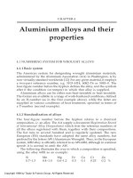
The stress-strain diagram for concrete of a
specified compressive strength is a curved line
(Fig. 8.1). Maximum stress is reached at a strain of
0.002 in/in, after which the curve descends.
Modulus of elasticity Ec generally used in
design for concrete is a secant modulus. In ACI 318,
“Building Code Requirements for Reinforced Concrete,” it is determined by
pffiffiffiffi
Ec ¼ w1:5 33 fc0 , psi
(8:3a)
where wc ¼ density of concrete lb/ft3
fc0 ¼ specified compressive strength at 28
days, psi
Downloaded from Digital Engineering Library @ McGraw-Hill (www.digitalengineeringlibrary.com)
Copyright © 2004 The McGraw-Hill Companies. All rights reserved.
Any use is subject to the Terms of Use as given at the website.
CONCRETE DESIGN AND CONSTRUCTION
Concrete Design and Construction n 8.3
Fig. 8.1
Stress-strain curves for concrete.
This equation applies when 90 pcf , wc , 155 pcf.
For normal-weight concrete, with w ¼ 145 lb/ft3,
pffiffiffiffi
Ec ¼ 57,000 fc0 , psi
(8:3b)
The modulus increases with age, as does the
strength. (See also Art. 5.6)
Durability is another important property of
concrete. Concrete should be capable of withstanding the weathering, chemical action, and wear
to which it will be subjected in service. Much of the
weather damage sustained by concrete is attributable to freezing and thawing cycles. Resistance of
concrete to such damage can be improved by using
appropriate cement types, lowering w/c ratio, providing proper curing, using alkali-resistant aggregates, using suitable admixtures, using an airentraining agent, or applying a protective coating
to the surface.
Chemical agents, such as inorganic acids, acetic
and carbonic acids, and sulfates of calcium, sodium,
magnesium, potassium, aluminum, and iron, disintegrate or damage concrete. When contact
between these agents and concrete may occur, the
concrete should be protected with a resistant coating. For resistance to sulfates, Type V portland
cement may be used (Art. 5.6). Resistance to wear
usually is achieved by use of a high-strength, dense
concrete made with hard aggregates.
Watertightness is an important property of
concrete that can often be improved by reducing
the amount of water in the mix. Excess water leaves
voids and cavities after evaporation, and if they
are interconnected, water can penetrate or pass
through the concrete. Entrained air (minute bubbles) usually increases watertightness, as does
prolonged thorough curing.
Volume change is another characteristic of
concrete that should be taken into account.
Expansion due to chemical reactions between the
ingredients of concrete may cause buckling and
drying shrinkage may cause cracking.
Expansion due to alkali-aggregate reaction can
be avoided by selecting nonreactive aggregates. If
reactive aggregates must be used, expansion may
be reduced or eliminated by adding pozzolanic
material, such as fly ash, to the mix. Expansion due
to heat of hydration of cement can be reduced by
Downloaded from Digital Engineering Library @ McGraw-Hill (www.digitalengineeringlibrary.com)
Copyright © 2004 The McGraw-Hill Companies. All rights reserved.
Any use is subject to the Terms of Use as given at the website.
CONCRETE DESIGN AND CONSTRUCTION
8.4 n Section Eight
keeping cement content as low as possible, using
Type IV cement (Art. 5.6), and chilling the aggregates, water, and concrete in the forms. Expansion
due to increases in air temperature may be
decreased by producing concrete with a lower
coefficient of expansion, usually by using coarse
aggregates with a lower coefficient of expansion.
Drying shrinkage can be reduced principally by
cutting down on water in the mix. But less cement
also will reduce shrinkage, as will adequate moist
curing. Addition of pozzolans, however, unless
enabling a reduction in water, may increase drying
shrinkage.
Autogenous volume change, a result of chemical
reaction and aging within the concrete and usually
shrinkage rather than expansion, is relatively independent of water content. This type of shrinkage
may be decreased by using less cement, and sometimes by using a different cement.
Whether volume change will damage the concrete often depends on the restraint present. For
example, a highway slab that cannot slide on the
subgrade while shrinking may crack; a building
floor that cannot contract because it is anchored to
relatively stiff girders also may crack. Hence, consideration should always be given to eliminating
restraints or resisting the stresses they may cause.
Creep is strain that occurs under a sustained
load. The concrete continues to deform, but at a
rate that diminishes with time. It is approximately
proportional to the stress at working loads and
increases with increasing water-cement ratio. It
decreases with increase in relative humidity. Creep
increases the deflection of concrete beams and
scabs and causes loss of prestress.
Density of ordinary sand-and-gravel concrete
usually is about 145 lb/ft3. It may be slightly lower if
the maximum size of coarse aggregate is less than
11⁄2 in. It can be increased by using denser aggregate, and it can be decreased by using lightweight
aggregate, increasing the air content, or incorporating a foaming, or expanding, admixture.
(J. G. MacGregor, “Reinforced Concrete,”
McGraw-Hill Book Company, New York
(books.mcgraw-hill.com); M. Fintel, “Handbook
of Concrete Engineering,” 2nd ed., Van Nostrand
Reinhold, New York.)
8.2
Lightweight Concretes
Concrete lighter in weight than ordinary sand-andgravel concrete is used principally to reduce dead
load, or for thermal insulation, nailability, or fill.
Structural lightweight concrete must be of sufficient density to satisfy fire ratings.
Lightweight concrete generally is made by
using lightweight aggregates or using gas-forming
or foaming agents, such as aluminum powder,
which are added to the mix. The lightweight aggregates are produced by expanding clay, shale,
slate, diatomaceous shale, perlite obsidian, and
vermiculite with heat and by special cooling of
blast-furnace slag. They also are obtained from
natural deposits of pumice, scoria, volcanic cinders, tuff, and diatomite, and from industrial
cinders. Usual ranges of weights obtained with
some lightweight aggregates are listed in Table 8.1.
Production of lightweight-aggregate concretes
is more difficult than that of ordinary concrete
because aggregates vary in absorption of water,
specific gravity, moisture content, and amount and
grading of undersize. Frequent unit-weight and
slump tests are necessary so that cement and water
content of the mix can be adjusted, if uniform
results are to be obtained. Also, the concretes
usually tend to be harsh and difficult to place and
finish because of the porosity and angularity of the
aggregates. Sometimes, the aggregates may float to
the surface. Workability can be improved by increasing the percentage of fine aggregates or by
using an air-entraining admixture to incorporate
from 4 to 6% air. (See also ACI 211.2, “Recommended Practice for Selecting Proportions for
Structural Lightweight Concrete,” American Concrete Institute (www.aci-int.org).)
To improve uniformity of moisture content of
aggregates and reduce segregation during stockpiling and transportation, lightweight aggregate
Table 8.1 Approximate Weights of Lightweight
Concretes
Aggregate
Cinders:
Without sand
With sand
Shale or clay
Pumice
Scoria
Perlite
Vermiculite
Concrete Weight, lb/ft3
85
110 – 115
90 – 110
90 – 100
90 – 110
50 – 80
35 – 75
Downloaded from Digital Engineering Library @ McGraw-Hill (www.digitalengineeringlibrary.com)
Copyright © 2004 The McGraw-Hill Companies. All rights reserved.
Any use is subject to the Terms of Use as given at the website.
CONCRETE DESIGN AND CONSTRUCTION
Concrete Design and Construction n 8.5
should be wetted 24 h before use. Dry aggregate
should not be put into the mixer because the
aggregate will continue to absorb moisture after it
leaves the mixer and thus cause the concrete to
segregate and stiffen before placement is completed. Continuous water curing is especially important with lightweight concrete.
Other types of lightweight concretes may be
made with organic aggregates, or by omission of
fines, or gap grading, or replacing all or part of the
aggregates with air or gas. Nailing concrete usually
is made with sawdust, although expanded slag,
pumice, perlite, and volcanic scoria also are
suitable. A good nailing concrete can be made
with equal parts by volume of portland cement,
sand, and pine sawdust, and sufficient water to
produce a slump of 1 to 2 in. The sawdust should
be fine enough to pass through a 1⁄4 -in screen and
coarse enough to be retained on a No. 16 screen.
(Bark in the sawdust may retard setting and
weaken the concrete.) The behavior of this type of
concrete depends on the type of tree from which
the sawdust came. Hickory, oak, or birch may not
give good results (“Concrete Manual,” U.S. Bureau
of Reclamation, Government Printing Office,
Washington, DC, 20402 (www.gpo.gov)). Some
insulating lightweight concretes are made with
wood chips as aggregate.
For no-fines concrete, 20 to 30% entrained air
replaces the sand. Pea gravel serves as the coarse
aggregate. This type of concrete is used where low
dead weight and insulation are desired and
strength is not important. No-fines concrete may
weigh from 105 to 118 lb/ft3 and have a compressive strength from 200 to 1000 psi.
A porous concrete may be made by gap grading
or single-size aggregate grading. It is used where
drainage is desired or for light weight and low conductivity. For example, drain tile may be made with
a No. 4 to 3⁄8 - or 1⁄2 -in aggregate and a low watercement ratio. Just enough cement is used to bind
the aggregates into a mass resembling popcorn.
Gas and foam concretes usually are made with
admixtures. Foaming agents include sodium lauryl
sulfate, alkyl aryl sulfonate, certain soaps, and
resins. In another process, the foam is produced by
the type of foaming agents used to extinguish fires,
such as hydrolyzed waste protein. Foam concretes
range in weight from 20 to 110 lb/ft3.
Aluminum powder, when used as an admixture, expands concrete by producing hydrogen
bubbles. Generally, about 1⁄4 lb of the powder per
bag of cement is added to the mix, sometimes with
an alkali, such as sodium hydroxide or trisodium
phosphate, to speed the reaction.
The heavier cellular concretes have sufficient
strength for structural purposes, such as floor slabs
and roofs. The lighter ones are weak but provide
good thermal and acoustic insulation or are useful
as fill; for example, they are used over structural
floor slabs to embed electrical conduit.
(ACI 213R, “Guide for Structural LightweightAggregate Concrete,” and 211.2 “Recommended
Practice for Selecting Proportions for Structural
Lightweight Concrete,” American Concrete Institute, 38800 Country Club Drive Farmington Hills,
MI, 48331 (www.aci-int.org).)
8.3
Heavyweight Concretes
Concrete weighing up to about 385 lb/ft3 can be
produced by using heavier-than-ordinary aggregate. Theoretically, the upper limit can be achieved
with steel shot as fine aggregate and steel punchings as coarse aggregate. (See also Art. 5.6.) The
heavy concretes are used principally in radiation
shields and counterweights.
Concrete made with barite develops an optimum density of 232 lb/ft3 and compressive
strength of 6000 psi; with limonite and magnetite,
densities from 210 to 224 lb/ft3 and strengths of
3200 to 5700 psi; with steel punchings and sheared
bars as coarse aggregate and steel shot for fine
aggregate, densities from 250 to 288 lb/ft3 and
strengths of about 5600 psi. Gradings and mix
proportions are similar to those used for conventional concrete. These concretes usually do not
have good resistance to weathering or abrasion.
Structural Concrete
8.4
Proportioning and
Mixing Concrete
Components of a mix should be selected to
produce a concrete with the desired characteristics
for the service conditions and adequate workability
at the lowest cost. For economy, the amount of
cement should be kept to a minimum. Generally,
this objective is facilitated by selecting the largestsize coarse aggregate consistent with job requirements and good gradation, to keep the volume of
Downloaded from Digital Engineering Library @ McGraw-Hill (www.digitalengineeringlibrary.com)
Copyright © 2004 The McGraw-Hill Companies. All rights reserved.
Any use is subject to the Terms of Use as given at the website.
CONCRETE DESIGN AND CONSTRUCTION
8.6 n Section Eight
voids small. The smaller this volume, the less
cement paste needed to fill the voids.
The water-cement ratio, for workability, should
be as large as feasible to yield a concrete with
the desired compressive strength, durability, and
watertightness and without excessive shrinkage.
Water added to a stiff mix improves workability,
but an excess of water has deleterious effects
(Art. 8.1).
8.4.1
Proportioning Concrete Mixes
A concrete mix is specified by indicating the
weight, in pounds, of water, cement, sand, coarse
aggregate, and admixture to be used per cubic yard
of mixed concrete. In addition, type of cement,
fineness modulus of the aggregates, and maximum
sizes of aggregates should be specified. (In the past,
one method of specifying a concrete mix was to give
the ratio, by weight, of cement to sand to coarse
aggregate; for example, 1 : 2 : 4; plus the minimum
cement content per cubic yard of concrete.)
Because of the large number of variables
involved, it usually is advisable to proportion concrete mixes by making and testing trial batches.
A start is made with the selection of the watercement ratio. Then, several trial batches are made
with varying ratios of aggregates to obtain the
desired workability with the least cement. The
aggregates used in the trial batches should have the
same moisture content as the aggregates to be used
on the job. The amount of mixing water to be used
must include water that will be absorbed by dry
aggregates or must be reduced by the free water in
wet aggregates. The batches should be mixed by
machine, if possible, to obtain results close to those
that would be obtained in the field. Observations
should be made of the slump of the mix and
Table 8.2 Estimated Compressive Strength of
Concrete for Various Water-Cement Ratios*
28-day Compressive Strength
Water-Cement
Ratio by Weight
0.40
0.45
0.50
0.55
0.60
0.65
0.70
Air-Entrained
Concrete
Non-Air-Entrained
Concrete
4,300
3,900
3,500
3,100
2,700
2,400
2,200
5,400
4,900
4,300
3,800
3,400
3,000
2,700
* “Concrete Manual,” U.S. Bureau of Reclamation.
appearance of the concrete. Also, tests should be
made to evaluate compressive strength and other
desired characteristics. After a mix has been
selected, some changes may have to be made after
some field experience with it.
Table 8.2 estimates the 28-day compressive
strength that may be attained with various watercement ratios, with and without air entrainment.
Note that air entrainment permits a reduction of
water, so a lower water-cement ratio for a given
workability is feasible with air entrainment.
Table 8.3 lists recommended maximum sizes of
aggregate for various types of construction. These
tables may be used with Table 8.4 for proportioning
concrete mixes for small jobs where time or other
conditions do not permit proportioning by the trialbatch method. Start with mix B in Table 8.4
corresponding to the selected maximum size of
aggregate. Add just enough water for the desired
Table 8.3 Recommended Maximum Sizes of Aggregate*
Maximum Size, in, of Aggregate for
Minimum Dimension
of Section, in
5 or less
6 – 11
12– 29
30 or more
Reinforced-Concrete
Beams, Columns, Walls
—
3
⁄4 À11⁄2
11⁄2 À3
11⁄2 À3
Heavily Reinforced
Slabs
3
⁄4 – 1⁄2
11⁄2
3
3
Lightly Reinforced
or Unreinforced Slabs
⁄4 À1⁄2
11⁄2À3
3–6
6
3
* “Concrete Manual,” U.S. Bureau of Reclamation.
Downloaded from Digital Engineering Library @ McGraw-Hill (www.digitalengineeringlibrary.com)
Copyright © 2004 The McGraw-Hill Companies. All rights reserved.
Any use is subject to the Terms of Use as given at the website.
CONCRETE DESIGN AND CONSTRUCTION
Concrete Design and Construction n 8.7
Table 8.4
Typical Concrete Mixes*
Aggregate, lb per Bag of Cement
Maximum Size of
Aggregate, in
Mix
Designation
Bags of
Cement
per yd3
of Concrete
A
B
C
A
B
C
A
B
C
A
B
C
A
B
C
7.0
6.9
6.8
6.6
6.4
6.3
6.4
6.2
6.1
6.0
5.8
5.7
5.7
5.6
5.4
1
⁄2
3
⁄4
1
11⁄2
2
Sand
Air-Entrained
Concrete
Concrete
without Air
Gravel or
Crushed Stone
235
225
225
225
225
215
225
215
205
225
215
205
225
215
205
245
235
235
235
235
225
235
225
215
235
225
215
235
225
215
170
190
205
225
245
265
245
275
290
290
320
345
330
360
380
* “Concrete Manual,” U.S. Bureau of Reclamation.
workability. If the mix is undersanded, change to
mix A; if oversanded, change to mix C. Weights are
given for dry sand. For damp sand, increase the
weight of sand 10 lb, and for very wet sand, 20 lb,
per bag of cement.
8.4.2
Admixtures
These may be used to modify and control specific
characteristics of concrete. Major types of admixtures include set accelerators, water reducers, air
entrainers, and waterproofing compounds. In
general, admixtures are helpful in improving
concrete workability. Some admixtures, if not
administered properly, could have undesirable
side effects. Hence, every engineer should be
familiar with admixtures and their chemical
components as well as their advantages and
limitations. Moreover, admixtures should be used
in accordance with manufacturers’ recommendations and, if possible, under the supervision of
a manufacturer’s representative. Many admixtures
are covered by ASTM specifications.
Accelerating admixtures are used to reduce the
time of setting and accelerating early strength
development and are often used in cold weather,
when it takes too long for concrete to set naturally.
The best-known accelerator is calcium chloride,
but it is not recommended for use in prestressed
concrete, in reinforced concrete containing embedded dissimilar metals, or where progressive
corrosion of steel reinforcement can occur. Nonchloride, noncorrosive accelerating admixtures,
although more expensive than calcium chloride,
may be used instead.
Water reducers lubricate the mix. Most of the
water in a normal concrete mix is needed for
workability of the concrete. Reduction in the water
content of a mix may result in either a reduction in
the water-cement ratio (w/c) for a given slump and
cement content or an increased slump for the same
w/c and cement content. With the same cement
content but less water, the concrete attains greater
strength. As an alternative, reduction of the quantity of water permits a proportionate decrease in
cement and thus reduces shrinkage of the hardened concrete. An additional advantage of a waterreducing admixture is easier placement of concrete.
This, in turn, helps the workers and reduces the
possibility of honeycombed concrete. Some water-
Downloaded from Digital Engineering Library @ McGraw-Hill (www.digitalengineeringlibrary.com)
Copyright © 2004 The McGraw-Hill Companies. All rights reserved.
Any use is subject to the Terms of Use as given at the website.
CONCRETE DESIGN AND CONSTRUCTION
8.8 n Section Eight
reducing admixtures also act as retarders of
concrete set, which is helpful in hot weather and
in integrating consecutive pours of concrete.
High-range water-reducing admixtures, also
known as superplasticizers, behave much like conventional water-reducing admixtures. They help
the concrete achieve high strength and water
reduction without loss of workability. Superplasticizers reduce the interparticle forces that exist
between cement grains in the fresh paste, thereby
increasing the paste fluidity. However, they differ
from conventional admixtures in that superplasticizers do not affect the surface tension of water
significantly, as a result of which, they can be used at
higher dosages without excessive air entrainment.
Air-entraining agents entrain minute bubbles
of air in concrete. This increases resistance of
concrete to freezing and thawing. Therefore, airentraining agents are extensively used in exposed
concrete. Air entrainment also affects properties of
fresh concrete by increasing workability.
Waterproofing chemicals may be added to a
concrete mix, but often they are applied as surface
treatments. Silicones, for example, are used on
hardened concrete as a water repellent. If applied
properly and uniformly over a concrete surface,
they can effectively prevent rainwater from penetrating the surface. (Some silicone coatings discolor with age. Most lose their effectiveness after a
number of years. When that happens, the surface
should be covered with a new coat of silicone for
continued protection.) Epoxies also may be used as
water repellents. They are much more durable, but
they also may be much more costly. Epoxies have
many other uses in concrete, such as protection of
wearing surfaces, patching compounds for cavities
and cracks, and glue for connecting pieces of
hardened concrete.
Miscellaneous types of admixtures are available
to improve properties of concrete either in the plastic
or the hardened state. These include polymerbonding admixtures used to produce modified
concrete, which has better abrasion resistance,
better resistance to freezing and thawing, and
reduced permeability; dampproofing admixtures;
permeability-reducing admixtures; and corrosioninhibiting admixtures.
plants consist of weighing and control equipment
and hoppers, or bins, for storing cement and
aggregates. Proportions are controlled by manually
operated or automatic scales. Mixing water is
measured out from measuring tanks or with the aid
of water meters.
Machine mixing is used wherever possible to
achieve uniform consistency of each batch. Good
results are obtained with the revolving-drum-type
mixer, commonly used in the United States, and
countercurrent mixers, with mixing blades rotating
in the direction opposite to that of the drum.
Mixing time, measured from the time the
ingredients, including water, are in the drum,
should be at least 1.5 min for a 1-yd3 mixer, plus
0.5 min for each cubic yard of capacity over 1 yd3.
But overmixing may remove entrained air and
increase fines, thus requiring more water to
maintain workability, so it is advisable also to set
a maximum on mixing time. As a guide, use three
times the minimum mixing time.
Ready-mixed concrete is batched in central
plants and delivered to various job-sites in trucks,
usually in mixers mounted on the trucks. The
concrete may be mixed en route or after arrival at
the site. Though concrete may be kept plastic and
workable for as long as 11⁄2 h by slow revolving of
the mixer, better control of mixing time can be
maintained if water is added and mixing started
after arrival of the truck at the job, where the
operation can be inspected.
(ACI 212.2, “Guide for Use of Admixtures in
Concrete,” ACI 211.1, “Recommended Practice for
Selecting Proportion for Normal and Heavyweight
Concrete,” ACI 213R, “Recommended Practice for
Selecting Proportions for Structural Lightweight
Concrete,” and ACI 304, “Recommended Practice
for Measuring, Mixing, Transporting, and Placing
Concrete,” American Concrete Institute, 38800
Country Club Drive Farmington Hills, MI 48331;
G. E. Troxell, H. E. Davis, and J. W. Kelly,
“Composition and Properties of Concrete,”
McGraw-Hill Book Company, New York (books.
mcgraw-hill.com); D. F. Orchard, “Concrete Technology,” John Wiley & Sons, Inc., New York;
M. Fintel, “Handbook of Concrete Engineering,”
2nd ed., Van Nostrand Reinhold, New York.)
8.4.3
8.5
Mixing Concrete Mixes
Components for concrete generally are stored in
batching plants before being fed to a mixer. These
Concrete Placement
When concrete is discharged from the mixer,
precautions should be taken to prevent segregation
Downloaded from Digital Engineering Library @ McGraw-Hill (www.digitalengineeringlibrary.com)
Copyright © 2004 The McGraw-Hill Companies. All rights reserved.
Any use is subject to the Terms of Use as given at the website.
CONCRETE DESIGN AND CONSTRUCTION
Concrete Design and Construction n 8.9
because of uncontrolled chuting as it drops into
buckets, hoppers, carts, or forms. Such segregation is less likely to occur with tilting mixers than
with nontilting mixers with discharge chutes that
let the concrete pass in relatively small streams.
To prevent segregation, a baffle, or better still, a
section of downpipe should be inserted at the end
of the chutes so that the concrete will fall vertically
into the center of the receptacle.
8.5.1
Concrete Transport and
Placement Equipment
Steel buckets, when selected for the job conditions
and properly operated, handle and place concrete
very well. But they should not be used if they
have to be hauled so far that there will be noticeable
separation, bleeding, or loss of slump exceeding
1 in. The discharge should be controllable in
amount and direction.
Rail cars and trucks sometimes are used to
transport concrete after it is mixed. But there is a
risk of stratification, with a layer of water on top,
coarse aggregate on the bottom. Most effective
prevention is use of dry mixes and air entrainment.
If stratification occurs, the concrete should be
remixed either as it passes through the discharge
gates or by passing small quantities of compressed
air through the concrete en route.
Chutes frequently are used for concrete placement. But the operation must be carefully controlled to avoid segregation and objectionable loss
of slump. The slope must be constant under varying loads and sufficiently steep to handle the
stiffest concrete to be placed. Long chutes should
be shielded from sun and wind to prevent evaporation of mixing water. Control at the discharge
end is of utmost importance to prevent segregation. Discharge should be vertical, preferably
through a short length of downpipe.
Tremies, or elephant trunks, deposit concrete
under water. Tremies are tubes about 1 ft or more in
diameter at the top, flaring slightly at the bottom.
They should be long enough to reach the bottom.
When concrete is being placed, the tremie is always
kept full of concrete, with the lower end immersed
in the concrete just deposited. The tremie is raised
as the level of concrete rises. Concrete should never
be deposited through water unless confined.
Belt conveyors for placing concrete also present
segregation and loss-of-slump problems. These
may be reduced by adopting the same precautions
as for transportation by trucks and placement with
chutes.
Sprayed concrete (shotcrete or gunite) is
applied directly onto a form by an air jet. A “gun,”
or mechanical feeder, mixer, and compressor comprise the principal equipment for this method of
placement. Compressed air and the dry mix are fed
to the gun, which jets them out through a nozzle
equipped with a perforated manifold. Water
flowing through the perforations is mixed with
the dry mix before it is ejected. Because sprayed
concrete can be placed with a low water-cement
ratio, it usually has high compressive strength. The
method is especially useful for building up shapes
without a form on one side.
Pumping is a suitable method for placing concrete, but it seldom offers advantages over other
methods. Curves, lifts, and harsh concrete reduce
substantially maximum pumping distance. For best
performance, an agitator should be installed in the
pump feed hopper to prevent segregation.
Barrows are used for transporting concrete very
short distances, usually from a hopper to the forms.
In the ordinary wheelbarrow, a worker can move
11⁄2 to 2 ft3 of concrete 25 ft in 3 min.
Concrete carts serve the same purpose as
wheelbarrows but put less load on the transporter.
Heavier and wider, the carts can handle 4.5 ft3.
Motorized carts with 1⁄2 -yd3 capacity also are
available.
Regardless of the method of transportation or
equipment used, the concrete should be deposited
as nearly as possible in its final position. Concrete
should not be allowed to flow into position but
should be placed in horizontal layers because then
less durable mortar concentrates in ends and corners where durability is most important.
8.5.2
Vibration of Concrete in Forms
This is desirable because it eliminates voids. The
resulting consolidation also ensures close contact of
the concrete with the forms, reinforcement, and
other embedded items. It usually is accomplished
with electric or pneumatic vibrators.
For consolidation of structural concrete and
tunnel-invert concrete, immersion vibrators are
recommended. Oscillation should be at least 7000
vibrations per minute when the vibrator head is
immersed in concrete. Precast concrete of relatively
Downloaded from Digital Engineering Library @ McGraw-Hill (www.digitalengineeringlibrary.com)
Copyright © 2004 The McGraw-Hill Companies. All rights reserved.
Any use is subject to the Terms of Use as given at the website.
CONCRETE DESIGN AND CONSTRUCTION
8.10 n Section Eight
small dimensions and concrete in tunnel arch and
sidewalls may be vibrated with vibrators rigidly
attached to the forms and operating at 8000
vibrations per minute or more. Concrete in canal
and lateral linings should be vibrated at more than
4000 vibrations per minute, with the immersion
type, though external vibration may be used for
linings less than 3 in thick. For mass concrete, with
3- and 6-in coarse aggregate, vibrating heads
should be at least 4 in in diameter and operate at
frequencies of at least 6000 vibrations per minute
when immersed. Each cubic yard should be vibrated for at least 1 min. A good small vibrator can
handle from 5 to 10 yd3/h and a large two-person,
heavy-duty type, about 50 yd3/h in uncramped
areas. Over vibration can be detrimental as it can
cause segregation of the aggregate and bleeding of
the concrete.
8.5.3
Construction Joints
A construction joint is formed when unhardened
concrete is placed against concrete that has become
so rigid that the new concrete cannot be incorporated into the old by vibration. Generally, steps
must be taken to ensure bond between the two.
Method of preparation of surfaces at construction joints vary depending on the orientation of the
surface.
(“Concrete Manual,” U.S. Bureau of Reclamation, Government Printing Office, Washington,
DC, 20402 (www.gpo.gov); ACI 311 “Recommended Practice for Concrete Inspection”; ACI 304,
“Recommended Practice for Measuring, Mixing,
Transporting, and Placing Concrete”; and ACI 506
“Recommended Practice for Shotcreting”; also,
ACI 304.2R, “Placing Concrete by Pumping
Methods,” ACI 304.1R, “Preplaced Aggregate
Concrete for Structural and Mass Concrete,” and
“ACI Manual of Concrete Inspection,” SP-2,
American Concrete Institute (www.aci-int.org).)
8.6
Finishing of Unformed
Concrete Surfaces
After concrete has been consolidated, screeding,
floating, and the first troweling should be performed with as little working and manipulation of
the surface as possible. Excessive manipulation
draws inferior fines and water to the top and can
cause checking, crazing, and dusting.
To avoid bringing fines and water to the top in
the rest of the finishing operations, each step
should be delayed as long as possible. If water
accumulates, it should be removed by blotting with
mats or draining, or it should be pulled off with a
loop of hose, and the next finishing operation
should be delayed until the water sheen disappears. Do not work neat cement into wet areas to
dry them.
Screeds are guides for a straightedge to bring a
concrete surface to a desired elevation or for a
template to produce a desired curved shape. The
screeds must be sufficiently rigid to resist distortion as the concrete is spread. They may be made of
lumber or steel pipe.
For floors, screeding is followed by hand
floating with wood floats or power floating.
Permitting a stiffer mix with a higher percentage
of large-size aggregate, power-driven floats with
revolving disks and vibrators produce a sounder,
more durable surface than wood floats. Floating
may begin as soon as the concrete surface has
hardened sufficiently to bear a person’s weight
without leaving an indentation. The operation
continues until hollows and humps are removed
or, if the surface is to be troweled, until a small
amount of mortar is brought to the top.
If a finer finish is desired, the surface may be
steel-troweled, by hand or by powered equipment.
This is done as soon as the floated surface has
hardened enough so that excess fine material will
not be drawn to the top. Heavy pressure during
troweling will produce a dense, smooth, watertight
surface. Do not permit sprinkling of cement or
cement and sand on the surface to absorb excess
water or facilitate troweling. If an extra hard finish
is desired, the floor should be troweled again when
it has nearly hardened.
Concrete surfaces dust to some extent and may
benefit from treatment with certain chemicals.
They penetrate the pores to form crystalline or
gummy deposits. Thus, they make the surface
less pervious and reduce dusting by acting as
plastic binders or by making the surface harder.
Poor-quality concrete floors may be improved
more by such treatments than high-quality concrete, but the improvement is likely to be temporary and the treatment will have to be repeated
periodically.
Downloaded from Digital Engineering Library @ McGraw-Hill (www.digitalengineeringlibrary.com)
Copyright © 2004 The McGraw-Hill Companies. All rights reserved.
Any use is subject to the Terms of Use as given at the website.
CONCRETE DESIGN AND CONSTRUCTION
Concrete Design and Construction n 8.11
(“Concrete Manual,” U.S. Bureau of Reclamation, U.S. Government Printing Office, Washington,
DC 20402 (www.gpo.gov).)
8.7
Forms for Concrete
Where form ties have to pass through the
concrete, they should be as small in cross section as
possible. (The holes they form sometimes have to
be plugged to stop leaks.) Ends of form ties should
be removed without spalling adjacent concrete.
Plastic coatings, proper oiling, or effective wetting can protect forms from deterioration, weather,
and shrinkage before concreting. Form surfaces
should be clean. They should be treated with a
suitable form-release oil or other coating that will
prevent the concrete from sticking to them.
A straight, refined, pale, paraffin-base mineral oil
usually is acceptable for wood forms. Synthetic
castor oil and some marine-engine oils are examples
of compounded oils that give good results on steel
forms. The oil or coating should be brushed or
sprayed evenly over the forms. It should not be
permitted to get on construction joint surfaces or
reinforcing bars because it will interfere with bond.
Forms should provide ready access for placement and vibration of concrete for inspection.
Formed areas should be clean of debris prior to
concrete placement.
Generally, forms are stationary. But for some
applications, such as highway pavements, precastconcrete slabs, silos, and service cores of buildings,
use of continuous moving forms—sliding forms or
slip forms—is advantageous.
Formwork retains concrete until it has set and
produces the desired shapes and, sometimes,
desired surface finishes. Forms must be supported
on falsework of adequate strength and sufficient
rigidity to keep deflections within acceptable
limits. The forms too must be strong and rigid, to
meet dimensional tolerances. But they also must be
tight, or mortar will leak out during vibration and
cause unsightly sand streaks and rock pockets. Yet
they must be low-cost and often easily demountable to permit reuse. These requirements are met
by steel, reinforced plastic, and plain or coated
lumber and plywood.
Unsightly bulges and offsets at horizontal joints
should be avoided. This can be done by resetting
forms with only 1 in of form lining overlapping the
existing concrete below the line made by a grade
strip. Also, the forms should be tied and bolted
close to the joint to keep the lining snug against
existing concrete (Fig. 8.2). If a groove along a joint
will not be esthetically objectionable, forming of a
groove along the joint will obscure unsightliness
often associated with construction joints (Art. 8.5.3).
8.7.1
Fig. 8.2 Form set to avoid bulges at a horizontal
joint in a concrete wall.
A slip form for vertical structures consists
principally of a form lining or sheathing about
4 ft high, wales or ribs, yokes, working platforms,
suspended scaffolds, jacks, climbing rods, and
control equipment (Fig. 8.3). Spacing of the
sheathing is slightly larger at the top to permit
easy upward movement. The wales hold the
sheathing in alignment, support the working
platforms and scaffolds, and transmit lifting forces
from yokes to sheathing. Each yoke has a
horizontal cross member perpendicular to the wall
and connected to a jack. From each end of the
member, vertical legs extend downward on
opposite sides of and outside the wall. The lower
end of each leg is attached to a bottom wale. The
jack pulls the slip form upward by climbing a
vertical steel rod, usually about 1 in in diameter,
embedded in the concrete. The suspended scaffolds
provide access for finishers to the wall. Slip-form
climbing rates range upward from about 2 to about
12 in/h.
Slip Forms
Downloaded from Digital Engineering Library @ McGraw-Hill (www.digitalengineeringlibrary.com)
Copyright © 2004 The McGraw-Hill Companies. All rights reserved.
Any use is subject to the Terms of Use as given at the website.
CONCRETE DESIGN AND CONSTRUCTION
8.12 n Section Eight
Fig. 8.3
8.7.2
Slip form for a concrete wall.
Form Removal
Stationary forms should be removed only after the
concrete has attained sufficient strength so that
there will be no noticeable deformation or damage
to the concrete. If supports are removed before
beams or floors are capable of carrying superimposed loads, they should be reshored until they
have gained sufficient strength.
Early removal of forms generally is desirable to
permit quick reuse, start curing as soon as possible,
and allow repairs and surface treatment while the
concrete is still green and conditions are favorable
for good bond. In cold weather, however, forms
should not be removed while the concrete is still
warm. Rapid cooling of the surface will cause
checking and surface cracks. For this reason also,
curing water applied to newly stripped surfaces
should not be much cooler than the concrete.
(R. L. Peurifoy, “Formwork for Concrete Structures,” 2nd ed., McGraw-Hill Book Company,
New York (books.mcgraw-hill.com); “Concrete
Manual,” U.S. Bureau of Reclamation, Government
Printing Office, Washington, DC, 20402 (www.gpo.
gov); ACI 347 “Recommended Practice for Concrete
Formwork,” “ACI Manual of Concrete Inspection,”
SP-2, and “Formwork for Concrete,” SP-4, American Concrete Institute (www.aci-int.org).)
8.8
Curing Concrete
While more than enough mixing water for hydration is incorporated into normal concrete mixes,
Downloaded from Digital Engineering Library @ McGraw-Hill (www.digitalengineeringlibrary.com)
Copyright © 2004 The McGraw-Hill Companies. All rights reserved.
Any use is subject to the Terms of Use as given at the website.
CONCRETE DESIGN AND CONSTRUCTION
Concrete Design and Construction n 8.13
drying of the concrete after initial set may delay or
prevent complete hydration. Curing includes all
operations after concrete has set that improve
hydration. Properly done for a sufficiently long
period, curing produces stronger, more watertight
concrete.
Methods may be classified as one of the
following: maintenance of a moist environment
by addition of water, sealing in the water in the
concrete, and those hastening hydration.
8.8.1
Curing by Surface Moistening
Maintenance of a moist environment by addition
of water is the most common field procedure.
Generally, exposed concrete surfaces are kept
continuously moist by spraying or ponding or by
a covering of earth, sand, or burlap kept moist.
Concrete made with ordinary and sulfate-resistant
cements (Types I, II, and V) should be cured this
way for 7 to 14 days, that made with low-heat
cement (Type IV) for at least 21 days. Concrete
made with high-early-strength cement should be
kept moist until sufficient strength has been
attained, as indicated by test cylinders.
8.8.2
Steam Curing
Precast concrete and concrete placed in cold
weather often are steam-cured in enclosures. Although this is a form of moist curing, hydration is
speeded by the higher-than-normal temperature,
and the concrete attains a high early strength.
Temperatures maintained usually range between
100 and 165 8F. Higher temperatures produce
greater strengths shortly after steam curing commences, but there are severe losses in strength after
2 days. A delay of 1 to 6 h before steam curing will
produce concrete with higher 24-h strength than if
the curing starts immediately after the concrete is
cast. This “preset” period allows early cement
reactions to occur and development of sufficient
hardness to withstand the more rapid temperature
curing to follow. Length of the preset period
depends on the type of aggregate and temperature.
The period should be longer for ordinary aggregate
than for lightweight and for higher temperatures.
Duration of steam curing depends on the concrete
mix, temperature, and desired results.
Autoclaving, or high-pressure steam curing,
maintains concrete in a saturated atmosphere at
temperatures above the boiling point of water.
Generally, temperatures range from 325 to 375 8F at
pressures from 80 to 170 psig. Main application is
for concrete masonry. Advantages claimed are high
early strength, reduced volume change in drying,
better chemical resistance, and lower susceptibility
to efflorescence. For steam curing, a preset period
of 1 to 6 h is desirable, followed by single- or twostage curing. Single-curing consists of a pressure
buildup of at least 3 h, 8 h at maximum pressure,
and rapid pressure release (20 to 30 min). The rapid
release vaporizes moisture from the block. In twostage curing, the concrete products are placed in
kilns for the duration of the preset period. Saturated steam then is introduced into the kiln. After
the concrete has developed sufficient strength to
permit handling, the products are removed from
the kiln, set in a compact arrangement, and placed
in the autoclave.
8.8.3
Curing by Surface Sealing
Curing concrete by sealing the water in can be
accomplished by either covering the concrete or
coating it with a waterproof membrane. When
coverings, such as heavy building paper or plastic
sheets, are used, care must be taken that the sheets
are sealed airtight and corners and edges are
adequately protected against loss of moisture.
Coverings can be placed as soon as the concrete has
been finished.
Coating concrete with a sealing compound
generally is done by spraying to ensure a continuous membrane. Brushing may damage the
concrete surface. Sealing compound may be
applied after the surface has stiffened so that it
will no longer respond to float finishing. But in hot
climates, it may be desirable, before spraying, to
moist cure for 1 day surfaces exposed to the sun.
Surfaces from which forms have been removed
should be saturated with water before spraying
with compound. But the compound should not be
applied to either formed or unformed surfaces
until the moisture film on them has disappeared.
Spraying should be started as soon as the surfaces
assume a dull appearance. The coating should be
protected against damage. Continuity must be
maintained for at least 28 days.
White or gray pigmented compound often is
used for sealing because it facilitates inspection
and reflects heat from the sun. Temperatures with
white pigments may be decreased as much as 40 8F,
reducing cracking caused by thermal changes.
Downloaded from Digital Engineering Library @ McGraw-Hill (www.digitalengineeringlibrary.com)
Copyright © 2004 The McGraw-Hill Companies. All rights reserved.
Any use is subject to the Terms of Use as given at the website.
CONCRETE DESIGN AND CONSTRUCTION
8.14 n Section Eight
Surfaces of ceilings and walls inside buildings
require no curing other than that provided by
forms left in place at least 4 days. But wood forms
are not acceptable for moist curing outdoor
concrete. Water should be applied at the top, for
example, by a soil-soaker hose and allowed to drip
down between the forms and the concrete.
(“Concrete Manual,” U.S. Bureau of Reclamation, Government Printing Office, Washington,
DC, 20402 (www.gpo.gov); ACI 517, “Recommended Practice for Atmospheric Pressure Steam
Curing of Concrete,” ACI 517.1R, “Low-Pressure
Steam Curing,” and ACI 516R, “High-Pressure
Steam Curing: Modern Practice, and Properties
of Autoclaved Products,” American Concrete
Institute (www.aci-int.org).)
8.9
Cold-Weather Concreting
Hydration of cement takes place in the presence of
moisture at temperatures above 50 8F. Methods used
during cold weather should prevent damage to
concrete from freezing and thawing at an early age.
(Concrete that is protected from freezing until it has
attained a compressive strength of at least 500 psi
will not be damaged by exposure to a single freezing
cycle.) Neglect of protection against freezing
can cause immediate destruction or permanent
weakening of concrete. Therefore, if concreting is
performed in cold weather, protection from low
Table 8.5
Concrete
temperatures and proper curing are essential.
Except within heated protective enclosures, little or
no external supply of moisture is required for curing
during cold weather. Under such conditions, the
temperature of concrete placed in the forms should
not be lower than the values listed in Table 8.5.
Protection against freezing should be provided until
concrete has gained sufficient strength to withstand
exposure to low temperatures, anticipated environment, and construction and service loads.
The time needed for concrete to attain the
strength required for safe removal of shores is
influenced by the initial concrete temperature at
placement, temperatures after placement, type of
cement, type and amount of accelerating admixture, and the conditions of protection and curing.
The use of high-early-strength cement or the
addition of accelerating admixtures may be an
economic solution when schedule considerations
are critical. The use of such admixtures does not
justify a reduction in the amount of protective
cover, heat, or other winter protection.
Although freezing is a danger to concrete, so is
overheating the concrete to prevent it. By accelerating chemical action, overheating can cause
excessive loss of slump, raise the water requirement for a given slump, and increase thermal
shrinkage. Rarely will mass concrete leaving the
mixer have to be at more than 55 8F and thinsection concrete at more than 75 8F.
Recommended Concrete Temperatures for Cold-Weather Construction—Air Entrained
Minimum Cross-Sectional Dimension, in
less than 12
12 to 36
36 to 72
72 or more
(a) Minimum Temperature of Concrete as Placed or Maintained, 8F
55
50
45
40
(b) Maximum Allowable Gradual Temperature Drop of Concrete in First
24 h after Protection Is Discounted, 8F
50
Temperature of air, 8F
30 or higher
0 to 30
0 or lower
40
30
20
(c) Minimum Temperature of Concrete as Mixed, 8F
60
65
70
55
60
65
50
55
60
Downloaded from Digital Engineering Library @ McGraw-Hill (www.digitalengineeringlibrary.com)
Copyright © 2004 The McGraw-Hill Companies. All rights reserved.
Any use is subject to the Terms of Use as given at the website.
45
50
55
CONCRETE DESIGN AND CONSTRUCTION
Concrete Design and Construction n 8.15
To obtain the minimum temperatures for concrete mixes in cold weather, the water and, if
necessary, the aggregates should be heated. The
proper mixing water temperature for the required
concrete temperature is based upon the temperature and weight of the materials in the concrete and
the free moisture on aggregates. To avoid flash set
of cement and loss of entrained air due to the
heated water, aggregates and water should be
placed in the mixer before the cement and airentraining agent so that the colder aggregates will
reduce the water temperature to below 80 8F.
When heating of aggregates is necessary, it is
best done with steam or hot water in pipes. Use of
steam jets is objectionable because of resulting
variations in moisture content of the aggregates.
For small jobs, aggregates may be heated over
culvert pipe in which fires are maintained, but care
must be taken not to overheat.
Before concrete is placed in the forms, the
interior should be cleared of ice, snow, and frost.
This may be done with steam under canvas or
plastic covers.
Concrete should not be placed on frozen earth. It
would lower the concrete temperature below the
minimum and may cause settlement on thawing. The
subgrade may be protected from freezing by a
covering of straw and tarpaulins or other insulating
blankets. If it does freeze, the subgrade must be
thawed deep enough so that it will not freeze back up
to the concrete during the required protection period.
The usual method of protecting concrete after it
has been cast is to enclose the structure with
tarpaulins or plastic and heat the interior. Since
corners and edges are especially vulnerable to low
temperatures, the enclosure should enclose corners
and edges, not rest on them. The enclosure must be
not only strong but windproof. If wind can
penetrate it, required concrete temperatures may
not be maintained despite high fuel consumption.
Heat may be supplied by live or piped steam,
salamanders, stoves, or warm air blown in through
ducts from heaters outside the enclosure. But strict
fire-prevention measures should be enforced.
When dry heat is used, the concrete should be
kept moist to prevent it from drying.
Concrete also may be protected with insulation.
For example, pavements may be covered with
layers of straw, shavings, or dry earth. For structures, forms may be insulated.
When protection is discontinued or when forms
are removed, precautions should be taken that the
drop in temperature of the concrete will be gradual.
Otherwise, the concrete may crack and deteriorate.
Table 8.5 lists recommended limitations on temperature drop in the first 24 hours. Special care
shall be taken with concrete test specimens used for
acceptance of concrete. Cylinders shall be properly
stored and protected in insulated boxes with a
thermometer to maintain temperature records.
(“Concrete Manual,” U.S. Bureau of Reclamation, Government Printing Office, Washington, DC
20402 (www.gpo.gov); ACI 306R “Cold-Weather
Concreting,” American Concrete Institute (www.
aci-int.org).)
8.10
Hot-Weather Concreting
Hot weather is defined as any combination of
the following: high ambient air temperature,
high concrete temperature, low relative humidity,
high wind velocity, and intense solar radiation.
Such weather may lead to conditions in mixing, placing, and curing concrete that can adversely affect
the properties and serviceability of the concrete.
The higher the temperature, the more rapid
the hydration of cement, the faster the evaporation
of mixing water, the lower the concrete strength
and the larger the volume change. Unless precautions are taken, setting and rate of hardening
will accelerate, shortening the available time for
placing and finishing the concrete. Quick stiffening
encourages undesirable additions of mixing water,
or retempering, and may also result in inadequate
consolidation and cold joints. The tendency to
crack is increased because of rapid evaporation of
water, increased drying shrinkage, or rapid cooling
of the concrete from its high initial temperature. If
an air-entrained concrete is specified, control of the
air content is more difficult. And curing becomes
more critical. Precautionary measures required on
a calm, humid day will be less restrictive than those
required on a dry, windy, sunny day, even if the air
temperatures are identical.
Placement of concrete in hot weather is too
complex to be dealt with adequately by simply
setting a maximum temperature at which concrete
may be placed. A rule of thumb, however, has been
that concrete temperature during placement
should be maintained as much below 90 8F as is
economically feasible.
The following measures are advisable in hot
weather: The concrete should have ingredients and
Downloaded from Digital Engineering Library @ McGraw-Hill (www.digitalengineeringlibrary.com)
Copyright © 2004 The McGraw-Hill Companies. All rights reserved.
Any use is subject to the Terms of Use as given at the website.
CONCRETE DESIGN AND CONSTRUCTION
8.16 n Section Eight
proportions with satisfactory records in field use in
hot weather. To keep the concrete temperature
within a safe range, the concrete should be cooled
with iced water or cooled aggregate, or both. Also,
to minimize slump loss and other temperature
effects, the concrete should be transported, placed,
consolidated, and finished as speedily as possible.
Materials and facilities not otherwise protected
from the heat should be shaded. Mixing drums
should be insulated or cooled with water sprays or
wet burlap coverings. Also, water-supply lines and
tanks should be insulated or at least painted white.
Cement with a temperature exceeding 170 8F
should not be used. Forms, reinforcing steel, and
the subgrade should be sprinklered with cool
water. If necessary, work should be done only at
night. Futhermore, the concrete should be protected against moisture loss at all times during
placing and curing.
Self-retarding admixtures counteract the accelerating effects of high temperature and lessen the
need for increase in mixing water. Their use should
be considered when the weather is so hot that the
temperature of concrete being placed is consistently above 75 8F.
Continuous water curing gives best results in
hot weather. Curing should be started as soon as
the concrete has hardened sufficiently to withstand
surface damage. Water should be applied to
formed surfaces while forms are still in place.
Surfaces without forms should be kept moist by
wet curing for at least 24 h. Moist coverings are
effective in eliminating evaporation loss from
concrete, by protecting it from sun and wind. If
moist curing is discontinued after the first day,
the surface should be protected with a curing
compound (Art. 8.8).
(ACI 305R, “Hot-Weather Concreting,” American Concrete Institute (www.aci-int.org).)
8.11
Contraction and
Expansion Joints
Contraction joints are used mainly to control
locations of cracks caused by shrinkage of concrete
after it has hardened. If the concrete, while shrinking, is restrained from moving, by friction or
attachment to more rigid construction, cracks are
likely to occur at points of weakness. Contraction
joints, in effect, are deliberately made weakness
planes. They are formed in the expectation that if a
crack occurs it will be along the neat geometric
pattern of a joint, and thus irregular, unsightly
cracking will be prevented. Such joints are used
principally in floors, roofs, pavements, and walls.
A contraction joint is an indentation in the
concrete. Width may be 1⁄4 or 3⁄8 in and depth onefourth the thickness of the slab. The indentation
may be made with a saw cut while the concrete still
is green but before appreciable shrinkage stress
develops. Or the joint may be formed by insertion
of a strip of joint material before the concrete sets or
by grooving the surface during finishing. Spacing
of joints depends on the mix, strength and thickness
of the concrete, and the restraint to shrinkage. The
indentation in highway and airport pavements
usually is filled with a sealing compound.
Construction joints occur where two successive
placements of concrete meet. They may be designed
to permit movement and/or to transfer load.
Expansion or isolation joints are used to help
prevent cracking due to thermal dimension changes in concrete. They usually are placed where
there are abrupt changes in thickness, offsets, or
changes in types of construction, for example,
between a bridge pavement and a highway
pavement. Expansion joints provide a complete
separation between two parts of a slab. The
opening must be large enough to prevent buckling
or other undesirable deformation due to expansion
of the concrete.
To prevent the joint from being jammed with
dirt and becoming ineffective, the opening is sealed
with a compressible material. For watertightness,
a flexible water stop should be placed across the
joint. And if load transfer is desired, dowels should
be embedded between the parts separated by the
joint. The sliding ends of the dowels should be
enclosed in a close-fitting metal cap or thimble, to
provide space for movement of the dowel during
expansion of the concrete. This space should be at
least 1⁄4 in longer than the width of the joint.
(ACI 504R, “Guide to Joint Sealants for Concrete
Structures,” American Concrete Institute (www.
aci-int.org).)
8.12
Steel Reinforcement
in Concrete
Because of the low tensile strength of concrete,
steel reinforcement is embedded in it to resist
tensile stresses. Steel, however, also is used to take
Downloaded from Digital Engineering Library @ McGraw-Hill (www.digitalengineeringlibrary.com)
Copyright © 2004 The McGraw-Hill Companies. All rights reserved.
Any use is subject to the Terms of Use as given at the website.
CONCRETE DESIGN AND CONSTRUCTION
Concrete Design and Construction n 8.17
compression, in beams and columns, to permit use
of smaller members. It serves other purposes too: It
controls strains due to temperature and shrinkage
and distributes load to the concrete and other
reinforcing steel; it can be used to prestress the
concrete; and it ties other reinforcing together for
easy placement or to resist lateral stresses.
Most reinforcing is in the form of bars or wires
whose surfaces may be smooth or deformed. The
latter type is generally used because it produces
better bond with the concrete because of the raised
pattern on the steel.
Bars range in diameter from 1⁄4 to 21⁄4 in
(Table 8.11, p 8.36). Sizes are designated by numbers, which are approximately eight times the nominal diameters. (See the latest edition of ASTM
“Specifications for Steel Bars for Concrete Reinforcement.” These also list the minimum yield
points and tensile strengths for each type of steel.)
Use of bars with yield points over 60 ksi for flexural
reinforcement is limited because special measures
are required to control cracking and deflection.
Wires usually are used for reinforcing concrete
pipe and, in the form of welded-wire fabric, for slab
reinforcement. The latter consists of a rectangular
grid of uniformly spaced wires, welded at all intersections, and meeting the minimum requirements
of ASTM A185 and A497. Fabric offers the
advantages of easy, fast placement of both
longitudinal and transverse reinforcement and
excellent crack control because of high mechanical
bond with the concrete. (Deformed wires are
designated by D followed by a number equal to
the nominal area, in2, times 100.) Bars and rods also
may be prefabricated into grids, by clipping or
welding (ASTM A184).
Sometimes, metal lath is used for reinforcing
concrete, for example, in thin shells. It may serve as
both form and reinforcing when concrete is applied
by spray (gunite or shotcrete.)
8.12.1
Bending and Placing
Reinforcing Steel
Bars are shipped by a mill to a fabricator in uniform
long lengths and in bundles of 5 or more tons. The
fabricator transports them to the job straight and
cut to length or cut and bent.
Bends may be required for beam-and-girder
reinforcing, longitudinal reinforcing of columns
where they change size, stirrups, column ties
and spirals, and slab reinforcing. Dimensions of
standard hooks and typical bends and tolerances
for cutting and bending are given in ACI 315,
“Manual of Standard Practice for Detailing Reinforced Concrete Structures,” American Concrete
Institute (www.aci-int.org).
Some preassembling of reinforcing steel is done
in the fabricating shop or on the job. Beam, girder,
and column steel often is wired into frames before
placement in the forms. Slab reinforcing may be
clipped or welded into grids, or mats, if not supplied as welded-wire fabric.
Some rust is permissible on reinforcing if it is
not loose and there is no appreciable loss of crosssectional area. In fact, rust, by creating a rough
surface, will improve bond between the steel and
concrete. But the bars should be free of loose rust,
scale, grease, oil, or other coatings that would
impair bond.
Bars should not be bent or straightened in any
way that will damage them. All reinforcement shall
be bent cold unless permitted by the engineer. If
heat is necessary for bending, the temperature
should not be higher than that indicated by a
cherry-red color (1200 8F), and the steel should be
allowed to cool slowly, not quenched, to 600 8F.
Reinforcing should be supported and tied in the
locations and positions called for in the plans. The
steel should be inspected before concrete is placed.
Neither the reinforcing nor other parts to be
embedded should be moved out of position before
or during the casting of the concrete.
Bars and wire fabric should not be kinked or
have unspecified curvatures when positioned.
Kinked and curved bars, including those misshaped by workers walking on them, may cause
the hardened concrete to crack when the bars are
tensioned by service loads.
Usually, reinforcing is set on wire bar supports,
preferably galvanized for exposed surfaces. Lowerlayer bars in slabs usually are supported on bolsters consisting of a horizontal wire welded to two
legs about 5 in apart. The upper layer generally is
supported on bolsters with runner wires on the
bottom so that they can rest on bars already in
place. Or individual or continuous high chairs can
be used to hold up a support bar, often a No. 5, at
appropriate intervals, usually 5 ft. An individual
high chair is a bar seat that looks roughly like an
inverted U braced transversely by another inverted
U in a perpendicular plane. A continuous high
chair consists of a horizontal wire welded to two
inverted-U legs 8 or 12 in apart. Beam and joist
Downloaded from Digital Engineering Library @ McGraw-Hill (www.digitalengineeringlibrary.com)
Copyright © 2004 The McGraw-Hill Companies. All rights reserved.
Any use is subject to the Terms of Use as given at the website.
CONCRETE DESIGN AND CONSTRUCTION
8.18 n Section Eight
chairs have notches to receive the reinforcing.
These chairs usually are placed at 5-ft intervals.
Although it is essential that reinforcement be
placed exactly where called for in the plans, some
tolerances are necessary. Reinforcement in beams
and slabs, walls and compression members should
be within + 3⁄800 for members where d 800 , + 1⁄200 for
members where d . 800 of the specified distance
from the tension or compression face. Lengthwise,
a cutting tolerance of + 1 in and a placement
tolerance of + 2 in are normally acceptable. If
length of embedment is critical, the designer
should specify bars 3 in longer than the computed
minimum to allow for accumulation of tolerances.
Spacing of reinforcing in wide slabs and tall walls
may be permitted to vary + 1⁄2 in or slightly more if
necessary to clear obstructions, so long as the
required number of bars are present.
Lateral spacing of bars in beams and columns,
spacing between multiple reinforcement layers,
and concrete cover over stirrups, ties, and spirals in
beams and columns should never be less than that
specified but may exceed it by 1⁄4 in. A variation in
setting of an individual stirrup or column hoop of
1 in may be acceptable, but the error should not be
permitted to accumulate.
(“CRSI Recommended Practice for Placing
Reinforcing Bars,” and “Manual of Standard
Practice,” Concrete Reinforcing Steel Institute,
180 North La Salle St., Chicago, IL 60601 (www.
crsi.org).)
8.12.2
Minimum Spacing of
Reinforcement
In buildings, the minimum clear distance between
parallel bars should be 1 in for bars up to No. 8 and
the nominal bar diameter for larger bars. For
columns, however, the clear distance between longitudinal bars should be at least 1.5 in for bars up to
No. 8 and 1.5 times the nominal bar diameter for
larger bars. And the clear distance between
multiple layers of reinforcement in building beams
and girders should be at least 1 in. Upper-layer
bars should be directly above corresponding bars
below. These minimum-distance requirements also
apply to the clear distance between a contact splice
and adjacent splices or bars.
A common requirement for minimum clear
distance between parallel bars in highway bridges
is 1.5 times the diameter of the bars, and spacing
center to center should be at least 1.5 times the
maximum size of coarse aggregate.
Many codes and specifications relate the
minimum bar spacing to maximum size of coarse
aggregate. This is done with the intention of
providing enough space for all of the concrete mix
to pass between the reinforcing. But if there is a
space to place concrete between layers of steel and
between the layers and the forms, and the concrete
is effectively vibrated, experience has shown that
bar spacing or form clearance does not have to
exceed the maximum size of coarse aggregate to
ensure good filling and consolidation. That portion
of the mix which is molded by vibration around
bars, and between bars and forms, is not inferior to
that which would have filled those parts had a
larger bar spacing been used. The remainder of the
mix in the interior, if consolidated layer after layer,
is superior because of its reduced mortar and water
content (“Concrete Manual,” U.S. Bureau of
Reclamation, Government Printing Office, Washington, D.C. 20402 (www.gpo.gov)).
Bundled Bars n Groups of parallel reinforcing
bars bundled in contact to act as a unit may be used
only when they are enclosed by ties or stirrups.
Four bars are the maximum permitted in a bundle,
and all must be deformed bars. If full-length bars
cannot be used between supports, then there
should be a stagger of at least 40 bar diameters
between any discontinuities. Also, the length of lap
should be increased 20% for a three-bar bundle and
33% for a four-bar bundle. In determining minimum clear distance between a bundle and parallel
reinforcing, the bundle should be treated as a single
bar of equivalent area.
8.12.3
Maximum Spacing
In walls and slabs in buildings, except for concretejoist construction, maximum spacing, center to
center, of principal reinforcement should be 18 in,
or three times the wall or slab thickness, whichever
is smaller.
8.12.4
Concept of Development
Length
Bond of steel reinforcement to the concrete in a
reinforced concrete member must be sufficient so
that the steel will yield before it is freed from the
Downloaded from Digital Engineering Library @ McGraw-Hill (www.digitalengineeringlibrary.com)
Copyright © 2004 The McGraw-Hill Companies. All rights reserved.
Any use is subject to the Terms of Use as given at the website.
CONCRETE DESIGN AND CONSTRUCTION
Concrete Design and Construction n 8.19
concrete. Furthermore, the length of embedment
must be adequate to prevent highly stressed
reinforcement from splitting relatively thin sections
of restraining concrete. Hence, design codes specify
a required length of embedment, called development length, for reinforcing steel. The concept of
development length is based on the attainable
average bond stress over the embedment length of
the reinforcement.
Each reinforcing bar at a section of a member
must develop on each side of the section the calculated tension or compression in the bar through
development length ld or end anchorage, or both.
Development of tension bars can be assisted by
hooks.
8.12.5
Tension Development
Lengths
For bars and deformed wire in tension, basic
development length is defined by Eqs. (8.4). For
No. 11 and smaller bars,
"
#
3 fy
abgl
pffiffiffiffi
db
(8:4)
ld ¼
40 fc0 (c þ ktr )=db
Where a ¼ traditional reinforcement location factor
b ¼ coating factor
ktr ¼ transverse reinforcement index
db ¼ bar diameter
8.12.6
Compression Development
Lengths
For bars in compression, the basic development
length ld is defined as
ld ¼
0:02fy db
pffiffiffiffi ! 0:0003db fy
fc0
(8:5)
but ld not be less than 8 in. See Table 8.6.
For fy greater than 60 ksi or concrete strengths
less than 3000 psi, the required development length
in Table 8.6 should be increased as indicated by
Eq. (8.5). The values in Table 8.6 may be multiplied
by the applicable factors:
a) reinforcement in excess of that required by
analyses:
As required
As provided
b) reinforcement enclosed within spiral reinforcement not less than 1⁄400 diameter and not more
than 400 pitch or within #4 ties spaced not more than
400 on center.
g ¼ reinforcement size factor
8.12.7
l ¼ lightweight aggregate factor
Because of the difficulty of transporting very long
bars, reinforcement cannot always be continuous.
When splices are necessary, it is advisable that they
c ¼ spacing or cover dimension
Table 8.6
Bar Lap Splices
Compression Development in Normal-Weight Concrete for Grade 60 Bars
fc0 (Normal-Weight Concrete)
Bar Size No.
3000 psi
3750 psi
4000 psi
Over 4444 psi*
3
4
5
6
7
8
9
10
11
14
18
8
11
14
17
19
22
25
28
31
38
50
8
10
12
15
17
20
22
25
27
34
44
8
10
12
15
17
19
22
24
27
34
43
8
9
11
14
16
18
20
23
25
32
41
* For fc0 . 4444 psi, minimum embedment ¼ 18db.
Downloaded from Digital Engineering Library @ McGraw-Hill (www.digitalengineeringlibrary.com)
Copyright © 2004 The McGraw-Hill Companies. All rights reserved.
Any use is subject to the Terms of Use as given at the website.
CONCRETE DESIGN AND CONSTRUCTION
8.20 n Section Eight
should be made where the tensile stress is less than
half the permissible stress.
Bars up to No. 11 in size may be spliced by
overlapping them and wiring them together.
Bars spliced by noncontact lap splices in flexural
members should not be spaced transversely farther
apart than one-fifth the required lap length or 6 in.
8.12.8
Welded or Mechanical
Splices
These other positive connections should be used for
bars larger than No. 11 and are an acceptable
alternative for smaller bars. Welding should conform to AWS D12.1, “Reinforcing Steel Welding
Code,” American Welding Society, 550 N.W. LeJeune
Road, Miami, FL 33126 (www.aws.org). Bars to be
spliced by welding should be butted and welded so
that the splice develops in tension at least 125% of
their specified yield strength. Mechanical coupling
devices should be equivalent in strength.
8.12.9
Tension Lap Splices
The length of lap for bars in tension should conform to the following, with ld taken as the tensile
development length for the full yield strength fy of
the reinforcing steel [Eq. (8.4)]:
Class A splices (lap of ld) are permitted where
both conditions 1 and 2 occur.
1. The area of reinforcement provided is at least
twice that required by analysis over the entire
lengths of splices.
2. No more than one-half of the total reinforcement
is spliced within the required lap length.
For tied compression members where the ties
have an area, in2, of at least 0.0015hs in the vicinity
of the lap, the lap length may be reduced to 83% of
the preceding requirements but not to less than
12 in (h is the overall thickness of the member, in,
and s is the tie spacing, in).
For spirally reinforced compression members,
the lap length may be reduced to 75% of the basic
required lap but not to less than 12 in.
In columns where reinforcing bars are offset and
one bar of a splice has to be bent to lap and contact
the other one, the slope of the bent bar should
not exceed 1 in 6. Portions of the bent bar above and
below the offset should be parallel to the column
axis. The design should account for a horizontal
thrust at the bend taken equal to at least 1.5 times
the horizontal component of the nominal stress
in the inclined part of the bar. This thrust should be
resisted by steel ties, or spirals, or members framing
into the column. This resistance should be provided
within a distance of 6 in of the point of the bend.
Where column faces are offset 3 in or more,
vertical bars should be lapped by separate dowels.
In columns, a minimum tensile strength at each
face equal to one-fourth the area of vertical reinforcement multiplied by fy should be provided at
horizontal cross sections where splices are located.
In columns with substantial bending, full tensile
splices equal to double the factored tensile stress in
the bar are required.
8.12.11
Splices of Welded-Wire
Fabric
Class B splices (lap of 1.3 ld) are required where
either 1 or 2 does not apply.
Bars in tension splices should lap at least 12 in.
Splices for tension tie members should be fully
welded or made with full mechanical connections
and should be staggered at least 30 in. Where feasible, splices in regions of high stress also should be
staggered.7
Wire reinforcing normally is spliced by lapping.
For plainwire fabric in tension, when the area of
reinforcing provided is more than twice that required, the overlap measured between outermost
cross wires should be at least 2 in or 1.5ld. Otherwise, the overlap should equal the spacing of the
cross wires but not less than 1.5ld nor 6 in. For
deformed wire fabric, the overlap measured
between outermost cross wires should be at least
2 in. The overlap should be at least 800 or 1.3ld.
8.12.10
8.12.12
Compression Lap Splices
For a bar in compression, the minimum length of a lap
splice should be the largest of 12 in, or 0.0005fy db,
for fc0 of 3000 psi or larger and steel yield strength fy
of 60 ksi or less, where db is the bar diameter.
Slab Reinforcement
Structural floor and roof slabs with principal reinforcement in only one direction should be reinforced for shrinkage and temperature stresses in a
perpendicular direction. The crossbars may be
Downloaded from Digital Engineering Library @ McGraw-Hill (www.digitalengineeringlibrary.com)
Copyright © 2004 The McGraw-Hill Companies. All rights reserved.
Any use is subject to the Terms of Use as given at the website.
CONCRETE DESIGN AND CONSTRUCTION
Concrete Design and Construction n 8.21
spaced at a maximum of 18 in or five times the slab
thickness. The ratio of reinforcement area of these
bars to gross concrete area should be at least
0.0020 for deformed bars with less than 60 ksi
yield strength, 0.0018 for deformed bars with 60 ksi
yield strength and welded-wire fabric with welded
intersections in the direction of stress not more than
12 in apart, and 0.0018 (60/fy) for bars with fy
greater than 60 ksi.
8.12.13
Concrete Cover
To protect reinforcement against fire and corrosion,
thickness of concrete cover over the outermost steel
should be at least that given in Table 8.7.
(ACI 318, “Building Code Requirements for
Reinforced Concrete,” American Concrete Institute; “Standard Specifications for Highway
Bridges,” American Association of State Highway
and Transportation Officials, 444 N. Capitol St.,
N.W., Washington, DC 20001 (www.aashto.org).)
8.13
Tendons
High-strength steel is required for prestressing
concrete to make the stress loss due to creep and
shrinkage of concrete and to other factors a small
percentage of the applied stress (Art. 8.37). This
type of loss does not increase as fast as increase in
strength in the prestressing steel, or tendons.
Tendons should have specific characteristics in
addition to high strength to meet the requirements of
prestressed concrete. They should elongate uniformly
Table 8.7 Cast-in-Place Concrete Cover for Steel
Reinforcement (Non-prestressed)
1. Concrete deposited against and permanently
exposed to the ground, 3 in.
2. Concrete exposed to seawater, 4 in; except
precast-concrete piles, 3 in.
3. Concrete exposed to the weather or in contact
with the ground after form removal, 2 in for bars
larger than No. 5 and 11⁄2 in for No. 5 or smaller.
4. Unexposed concrete slabs, walls, or joists, 3⁄4 in for
No. 11 and smaller, 11⁄2 in for No. 14 and No. 18 bars.
Beams, girders, and columns, 11⁄2 in. Shells and
folded-plate members, 3⁄4 in for bars larger than
No. 5, and 1⁄2 inch for No. 5 and smaller.
up to initial tension for accuracy in applying the
prestressing force. After the yield strength has been
reached, the steel should continue to stretch as stress
increases, before failure occurs. ASTM Specifications
for prestressing wire and strands, A421 and A416, set
the yield strength at 80 to 85% of the tensile strength.
Furthermore, the tendons should exhibit little or no
creep, or relaxation, at the high stresses used.
ASTM A421 covers two types of uncoated,
stress-relieved, high-carbon-steel wire commonly
used for linear prestressed-concrete construction.
Type BA wire is used for applications in which
cold-end deformation is used for end anchorages,
such as buttonheads. Type WA wire is intended for
end anchorages by wedges and where no cold-end
deformation of the wire is involved. The wire is
required to be stress-relieved by a continuousstrand heat treatment after it has been cold-drawn
to size. Type BA usually is furnished 0.196 and
0.250 in in diameter, with an ultimate strength of
240 ksi and yield strength (at 1% extension) of
192 ksi. Type WA is available in those sizes and
also 0.192 and 0.276 in in diameter, with ultimate
strengths ranging from 250 for the smaller diameters to 235 ksi for the largest. Yield strengths range
from 200 for the smallest to 188 ksi for the largest
(Table 8.8).
For pretensioning, where the steel is tensioned
before the concrete is cast, wires usually are used
individually, as is common for reinforced concrete.
For posttensioning, where the tendons are tensioned and anchored to the concrete after it has
attained sufficient strength, the wires generally are
placed parallel to each other in groups, or cables,
sheathed or ducted to prevent bond with the concrete.
A seven-wire strand consists of a straight center
wire and six wires of slightly smaller diameter
winding helically around and gripping it. High
friction between the center and outer wires is
important where stress is transferred between the
strand and concrete through bond. ASTM A416
covers strand with ultimate strengths of 250 and
270 ksi (Table 8.8).
Galvanized strands sometimes are used for
posttensioning, particularly when the tendons may
not be embedded in grout. Sizes normally available
range from a 0.5-in-diameter seven-wire strand, with
41.3-kip breaking strength, to 111⁄16 -in-diameter
strand, with 352-kip breaking strength. The colddrawn wire comprising the strand is stress-relieved
when galvanized, and stresses due to stranding are
offset by prestretching the strand to about 70% of
Downloaded from Digital Engineering Library @ McGraw-Hill (www.digitalengineeringlibrary.com)
Copyright © 2004 The McGraw-Hill Companies. All rights reserved.
Any use is subject to the Terms of Use as given at the website.
CONCRETE DESIGN AND CONSTRUCTION
8.22 n Section Eight
Table 8.8
Diameter,
in
Properties of Tendons
Weight per
ft-kip
Area,
in2
Ultimate
Strength
Uncoated Type WA Wire
0.276
0.250
0.196
0.192
0.05983
0.04909
0.03017
0.02895
203.2
166.7
102.5
98.3
235 ksi
240 ksi
250 ksi
250 ksi
Uncoated Type BA Wire
0.250
0.196
0.04909
0.03017
166.7
102.5
240 ksi
240 ksi
Uncoated Seven-Wire Strands, 250 Grade
1
⁄4
5
⁄16
3
⁄8
7
⁄16
1
⁄2
0.04
0.058
0.080
0.108
0.144
122
197
272
367
490
9 kips
14.5 kips
20 kips
27 kips
36 kips
270 Grade
3
⁄8
7
⁄16
1
⁄2
0.085
0.115
0.153
290
390
520
23 kips
31 kips
41.3 kips
its ultimate strength. Tendons 0.5 and 0.6 in in diameter are typically used sheathed and unbonded.
Hot-rolled alloy-steel bars used for prestressing
concrete generally are not so strong as wire or
strands. The bars usually are stress-relieved, then
cold-stretched to at least 90% of ultimate strength to
raise the yield point. The cold stretching also serves
as proof stressing, eliminating bars with defects.
(H. K. Preston and N. J. Sollenberger, “Modern
Prestressed Concrete,” McGraw-Hill Book Company, New York (books.mcgraw-hill.com); J. R.
Libby, “Modern Prestressed Concrete,” Van
Nostrand Reinhold Company, New York.)
8.14
Fabrication of
Prestressed-Concrete
Members
Prestressed concrete may be produced much like
high-strength reinforced concrete, either cast in
place or precast. Prestressing offers several advantages for precast members, which have to be
transported from casting bed to final position and
handled several times. Prestressed members
are lighter than reinforced members of the same
capacity, both because higher-strength concrete
generally is used and because the full cross section
is effective. In addition, prestressing of precast
members normally counteracts handling stresses.
And, if a prestressed, precast member survives the
full prestress and handling, the probability of its
failing under service loads is very small.
Two general methods of prestressing are commonly used—pretensioning and posttensioning—
and both may be used for the same member. See
also Art. 8.37.
Pretensioning, where the tendons are tensioned
before embedment in the concrete and stress
transfer from steel to concrete usually is by bond,
is especially useful for mass production of precast
elements. Often, elements may be fabricated in
long lines, by stretching the tendons (Art. 8.13)
between abutments at the ends of the lines. By use
of tiedowns and struts, the tendons may be draped
in a vertical plane to develop upward and downward components on release. After the tendons
have been jacked to their full stress, they are anchored to the abutments.
The casting bed over which the tendons are
stretched usually is made of a smooth-surface
concrete slab with easily stripped side forms of
steel. (Forms for pretensioned members must
permit them to move on release of the tendons.)
Separators are placed in the forms to divide the
long line into members of required length and
provide space for cutting the tendons. After the
concrete has been cast and has attained its specified
strength, generally after a preset period and steam
curing, side forms are removed. Then, the tendons
are detached from the anchorages at the ends of
the line and relieved of their stress. Restrained
from shortening by bond with the concrete, the
tendons compress it. At this time, it is safe to cut
the tendons between the members and remove the
members from the forms.
In pretensioning, the tendons may be tensioned
one at a time to permit the use of relatively light
jacks, in groups, or all simultaneously. A typical
stressing arrangement consists of a stationary
anchor post, against which jacks act, and a moving
crosshead, which is pushed by the jacks and to
which the tendons are attached. Usually, the
Downloaded from Digital Engineering Library @ McGraw-Hill (www.digitalengineeringlibrary.com)
Copyright © 2004 The McGraw-Hill Companies. All rights reserved.
Any use is subject to the Terms of Use as given at the website.
CONCRETE DESIGN AND CONSTRUCTION
Concrete Design and Construction n 8.23
tendons are anchored to a thick steel plate that
serves as a combination anchor plate and template.
It has holes through which the tendons pass to place
them in the desired pattern. Various patented grips
are available for anchoring the tendons to the plate.
Generally, they are a wedge or chuck type capable
of developing the full strength of the tendons.
Posttensioning frequently is used for cast-inplace members and long-span flexural members.
Cables or bars (Art. 8.13) are placed in the forms in
flexible ducts to prevent bond with the concrete.
They may be draped in a vertical plane to develop
upward and downward forces when tensioned.
After the concrete has been placed and has attained
sufficient strength, the tendons are tensioned by
jacking against the member and then are anchored
to it. Grout may be pumped into the duct to
establish bond with the concrete and protect the
tendons against corrosion. Applied at pressures of
75 to 100 psi, a typical grout consists of 1 part
portland cement, 0.75 parts sand (capable of
passing through a No. 30 sieve), and 0.75 parts
water, by volume.
Concrete with higher strengths than ordinarily
used for reinforced concrete offers economic
advantages for prestressed concrete. In reinforced
concrete, much of the concrete in a slab or beam is
assumed to be ineffective because it is in tension
and likely to crack under service loads. In
prestressed concrete, the full section is effective
because it is always under either compression or
very low tension. Furthermore, high-strength
concrete develops higher bond stresses with the
tendons, greater bearing strength to withstand the
pressure of anchorages, and a higher modulus of
elasticity. The last indicates reductions in initial
strain and camber when prestress is applied
initially and in creep strain. The reduction in creep
strain reduces the loss of prestress with time.
Generally, concrete with a 28-day strength of
5000 psi or more is advantageous for prestressed
concrete.
Concrete cover over prestressing steel, ducts,
and nonprestressed steel should be at least 3 in for
concrete surfaces in contact with the ground; 11⁄2 in
for prestressing steel and main reinforcing bars,
and 1 in for stirrups and ties in beams and girders,
1 in in slabs and joists exposed to the weather;
and 3⁄4 in for unexposed slabs and joists. In extremely corrosive atmospheres or other severe exposures, the amount of protective cover should be
increased.
Minimum clear spacing between pretensioning
steel at the ends of a member should be four times
the diameter of individual wires and three times the
diameter of strands. Some codes also require that
the spacing be at least 11⁄3 times the maximum size
of aggregate. (See also Art. 8.12.2.) Away from the
ends of a member, prestressing steel or ducts may
be bundled. Concentrations of steel or ducts, however, should be reinforced to control cracking.
Prestressing force may be determined by
measuring tendon elongation, by checking jack
pressure on a recently calibrated gage, or by using a
recently calibrated dynamometer. If several wires
or strands are stretched simultaneously, the
method used should be such as to induce approximately equal stress in each.
Splices should not be used in parallel-wire
cables, especially if a splice has to be made by
welding, which would weaken the wire. Failure is
likely to occur during tensioning of the tendon.
Strands may be spliced, if necessary, when the
coupling will develop the full strength of the
tendon, not cause it to fail under fatigue loading,
and does not displace sufficient concrete to weaken
the member.
High-strength bars are generally spliced
mechanically. The couplers should be capable of
developing the full strength of the bars without
decreasing resistance to fatigue and without
replacing an excessive amount of concrete.
Posttensioning End Anchorages n Anchor fittings are different for pretensioned and
posttensioned members. For pretensioned members, the fittings hold the tendons temporarily
against anchors outside the members and therefore can be reused. In posttensioning, the fittings
usually anchor the tendons permanently to the
members. In unbonded tendons, the sheathing is
typically plastic or impregnated paper.
A variety of patented fittings are available for
anchoring in posttensioned members. Such fittings
should be capable of developing the full strength
of the tendons under static and fatigue loadings.
The fittings also should spread the prestressing
force over the concrete or transmit it to a bearing
plate. Sufficient space must be provided for the
fittings in the anchor zone.
Generally, all the wires of a parallel-wire cable
are anchored with a single fitting (Figs. 8.4 and 8.5).
The type shown in Fig. 8.5 requires that the wires
Downloaded from Digital Engineering Library @ McGraw-Hill (www.digitalengineeringlibrary.com)
Copyright © 2004 The McGraw-Hill Companies. All rights reserved.
Any use is subject to the Terms of Use as given at the website.
CONCRETE DESIGN AND CONSTRUCTION
8.24 n Section Eight
Fig. 8.4
Conical wedge anchorage for prestressing wires.
be cut to exact length and a buttonhead be coldformed on the ends for anchoring.
The wedge type in Fig. 8.4 requires a doubleacting jack. One piston, with the wires wedged to it,
stresses them, and a second piston forces the male
cone into the female cone to grip the tendons.
Normally, a hole is provided in the male cone for
grouting the wires. After final stress is applied, the
anchorage may be embedded in concrete to prevent corrosion and improve appearance.
Fig. 8.5 Detail at end of prestressed concrete member. (a) End anchorage for button-headed wires.
(b) Externally threaded stressing head. (c) Internally threaded stressing head. Heads are used for
attachment to stressing jack.
Downloaded from Digital Engineering Library @ McGraw-Hill (www.digitalengineeringlibrary.com)
Copyright © 2004 The McGraw-Hill Companies. All rights reserved.
Any use is subject to the Terms of Use as given at the website.
CONCRETE DESIGN AND CONSTRUCTION
Concrete Design and Construction n 8.25
With the buttonhead type, a stressing rod may
be screwed over threads on the circumference of a
thick, steel stressing washer (Fig. 8.5b) or into a
center hole in the washer (Fig. 8.5c). The rod then is
bolted to a jack. When the tendons have been
stressed, the washer is held in position by steel
shims inserted between it and a bearing plate
embedded in the member. The jack pressure then
can be released and the jack and stressing rod
removed. Finally, the anchorage is embedded in
concrete.
Posttensioning bars may be anchored individually with steel wedges (Fig. 8.6a) or by tightening a
nut against a bearing plate (Fig. 8.6b). The former
has the advantage that the bars do not have to be
threaded.
Posttensioning strands normally are shop-fabricated in complete assemblies, cut to length, anchor
fittings attached, and sheathed in flexible duct.
Swaged to the strands, the anchor fittings have a
threaded steel stud projecting from the end. The
threaded stud is used for jacking the stress into the
strand and for anchoring by tightening a nut
against a bearing plate in the member (Fig. 8.7).
To avoid overstressing and failure in the anchorage zone, the anchorage assembly must be
Fig. 8.6 End anchorages for bars. (a) Conical
wedge. (b) Nut and washer acting against a bearing
plate at a threaded end of tendon.
Fig. 8.7 Swaged fitting for strands. Prestress is
maintained by tightening the nut against the bearing plate.
placed with care. Bearing plates should be placed
perpendicular to the tendons to prevent eccentric
loading. Jacks should be centered for the same
reason and so as not to scrape the tendons against
the plates. The entire area of the plates should bear
against the concrete.
Prestress normally is applied with hydraulic
jacks. The amount of prestressing force is determined by measuring tendon elongation and comparing with an average load-elongation curve for
the steel used. In addition, the force thus determined should be checked against the jack pressure
registered on a recently calibrated gage or by use of
a recently calibrated dynamometer. Discrepancies
of less than 5% may be ignored.
When prestressed-concrete beams do not have a
solid rectangular cross section in the anchorage
zone, an enlarged end section, called an end block,
may be necessary to transmit the prestress from the
tendons to the full concrete cross section a short
distance from the anchor zone. End blocks also are
desirable for transmitting vertical and lateral forces
to supports and to provide adequate space for the
anchor fittings for the tendons.
The transition from end block to main cross
section should be gradual (Fig. 8.8). Length of end
block, from beginning of anchorage area to the start
of the main cross section, should be at least 24 in.
The length normally ranges from three-fourths the
depth of the member for deep beams to the full
depth for shallow beams. The end block should be
reinforced vertically and horizontally to resist
tensile bursting and spalling forces induced by the
concentrated loads of the tendons. In particular, a
grid of reinforcing should be placed directly
behind the anchorages to resist spalling.
Downloaded from Digital Engineering Library @ McGraw-Hill (www.digitalengineeringlibrary.com)
Copyright © 2004 The McGraw-Hill Companies. All rights reserved.
Any use is subject to the Terms of Use as given at the website.