AASHTO guide specifications for LRFD seismic bridge design
Bạn đang xem bản rút gọn của tài liệu. Xem và tải ngay bản đầy đủ của tài liệu tại đây (7.79 MB, 249 trang )
i
© 2009 by the American Association of State Highway and Transportation Officials.
All rights reserved. Duplication is a violation of applicable law.
American Association of State Highway and Transportation Officials
444 North Capitol Street, NW Suite 249
Washington, DC 20001
202-624-5800 phone/202-624-5806 fax
www.transportation.org
© 2009 by the American Association of State Highway and Transportation Officials. All rights reserved. Duplication is a
violation of applicable law.
ISBN: 978-1-56051-396-4
Publication Code: LRFDSEIS-1
© 2009 by the American Association of State Highway and Transportation Officials.
All rights reserved. Duplication is a violation of applicable law.
EXECUTIVE COMMITTEE
2007–2008
Voting Members
Officers:
President: Allen D. Biehler, Pennsylvania
Vice President: Larry L. “Butch” Brown, Mississippi
Secretary-Treasurer: Carlos Braceras, Utah
Regional Representatives:
REGION I:
Carolann Wicks, Delaware, One-Year Term
Joseph Marie, Connecticut, Two-Year Term
REGION II:
Larry L. “Butch” Brown, Mississippi, One-Year Term
Dan Flowers, Arkansas, Two-Year Term
REGION III: Kirk T. Steudle Michigan, One-Year Term
Nancy J. Richardson, Iowa, Two-Year Term
REGION IV: Rhonda G. Faught, New Mexico, One-Year Term
Will Kempton, California, Two-Year Term
Nonvoting Members
Immediate Past President: Pete K. Rahn, Missouri
AASHTO Executive Director: John Horsley, Washington, DC
iii
© 2009 by the American Association of State Highway and Transportation Officials.
All rights reserved. Duplication is a violation of applicable law.
HIGHWAYS SUBCOMMITTEE ON BRIDGES AND STRUCTURES, 2008
MALCOLM T. KERLEY, Chair
KEVIN THOMPSON, Vice Chair
M. MYINT LWIN, Federal Highway Administration, Secretary
FIRAS I. SHEIKH IBRAHIM, Federal Highway Administration, Assistant Secretary
NORTH CAROLINA, Greg R. Perfetti
NORTH DAKOTA, Terrence R. Udland
OHIO, Timothy J. Keller, Jawdat Siddiqi
OKLAHOMA, Robert J. Rusch, Gregory D. Allen
OREGON, Bruce V. Johnson, Hormoz Seradj
PENNSYLVANIA, Thomas P. Macioce, Harold C.
“Hal” Rogers, Jr., Lou Ruzzi
PUERTO RICO, Jaime Cabré
RHODE ISLAND, David Fish
SOUTH CAROLINA, Barry W. Bowers, Jeff Sizemore
SOUTH DAKOTA, Kevin Goeden
TENNESSEE, Edward P. Wasserman
TEXAS, William R. Cox, David P. Hohmann
U.S. DOT, M. Myint Lwin, Firas I. Sheikh Ibrahim, Hala
Elgaaly
UTAH, Richard Miller
VERMONT, William Michael Hedges
VIRGINIA, Malcolm T. Kerley, Kendal Walus, Prasad
L. Nallapaneni, Julius F. J. Volgyi, Jr.
WASHINGTON, Jugesh Kapur, Tony M. Allen, Bijan
Khaleghi
WEST VIRGINIA, Gregory Bailey
WISCONSIN, Scot Becker, Beth A. Cannestra, Finn
Hubbard
WYOMING, Gregg C. Fredrick, Keith R. Fulton
ALABAMA, John F. Black, William F. Conway, George
H. Conner
ALASKA, Richard A. Pratt
ARIZONA, Jean A. Nehme
ARKANSAS, Phil Brand
CALIFORNIA, Kevin Thompson, Susan Hida, Barton J.
Newton
COLORADO, Mark A. Leonard, Michael G. Salamon
CONNECTICUT, Gary J. Abramowicz, Julie F. Georges
DELAWARE, Jiten K. Soneji, Barry A. Benton
DISTRICT OF COLUMBIA, Nicolas Glados, L.
Donald Cooney, Konjit “Connie” Eskender
FLORIDA, Robert V. Robertson, Jr., Marcus Ansley, Andre
Pavlov
GEORGIA, Paul V. Liles, Jr., Brian Summers
HAWAII, Paul T. Santo
IDAHO, Matthew M. Farrar
ILLINOIS, Ralph E. Anderson, Thomas J. Domagalski
INDIANA, Anne M. Rearick
IOWA, Norman L. McDonald
KANSAS, Kenneth F. Hurst, James J. Brennan, Loren R.
Risch
KENTUCKY, Allen Frank
LOUISIANA, Hossein Ghara, Arthur D’Andrea, Paul
Fossier
MAINE, David Sherlock, Jeffrey S. Folsom
MARYLAND, Earle S. Freedman, Robert J. Healy
MASSACHUSETTS, Alexander K. Bardow
MICHIGAN, Steven P. Beck, David Juntunen
MINNESOTA, Daniel L. Dorgan, Kevin Western
MISSISSIPPI, Mitchell K. Carr, B. Keith Carr
MISSOURI, Dennis Heckman, Michael Harms
MONTANA, Kent M. Barnes
NEBRASKA, Lyman D. Freemon, Mark Ahlman,
Hussam “Sam” Fallaha
NEVADA, Mark P. Elicegui, Marc Grunert, Todd
Stefonowicz
NEW HAMPSHIRE, Mark W. Richardson, David L. Scott
NEW JERSEY, Richard W. Dunne
NEW MEXICO, Jimmy D. Camp
NEW YORK, George A. Christian, Donald F. Dwyer,
Arthur P. Yannotti
ALBERTA, Tom Loo
NEW BRUNSWICK, Doug Noble
NOVA SCOTIA, Mark Pertus
ONTARIO, Bala Tharmabala
SASKATCHEWAN, Howard Yea
GOLDEN GATE BRIDGE, Kary H. Witt
N.J. TURNPIKE AUTHORITY, Richard J. Raczynski
N.Y. STATE BRIDGE AUTHORITY, William J. Moreau
PENN. TURNPIKE COMMISSION, Gary L. Graham
SURFACE DEPLOYMENT AND DISTRIBUTION
COMMAND TRANSPORTATION
ENGINEERING AGENCY, Robert D. Franz
U.S. ARMY CORPS OF ENGINEERS—
DEPARTMENT OF THE ARMY, Paul C. T. Tan
U.S. COAST GUARD, Nick E. Mpras, Jacob Patnaik
U.S. DEPARTMENT OF AGRICULTURE—
FOREST SERVICE, John R. Kattell
iv
© 2009 by the American Association of State Highway and Transportation Officials.
All rights reserved. Duplication is a violation of applicable law.
FOREWORD
Following the 1971 San Fernando earthquake, significant effort was expended to develop comprehensive design
guidelines for the seismic design of bridges. That effort led to updates of both the AASHTO and Caltrans design
provisions and ultimately resulted in the development of ATC-6, Seismic Design Guidelines for Highway Bridges, which
was published in 1981. That document was subsequently adopted by AASHTO as a Guide Specification in 1983; the
guidelines were formally adopted into the Standard Specifications for Highway Bridges in 1991, then revised and
reformatted as Division I-A. Later, Division I-A became the basis for the seismic provisions included in the AASHTO
LRFD Bridge Design Specifications.
After damaging earthquakes in 1980s and 1990s, and as more recent research efforts were completed, it became clear
that improvements to the seismic design practice for bridges should be undertaken. Several efforts culminated in the
publication of ATC-32, Improved Seismic Design Criteria for California Bridges: Provisional Recommendations in 1996;
the development of Caltrans’ Seismic Design Criteria; publication of MCEER/ATC-49 (NCHRP 12-49), Recommended
LRFD Guidelines for the Seismic Design of Highway Bridges in 2003; and the development of the South Carolina Seismic
Design Specifications in 2001. Thus in 2005, with the T-3 Seismic Design Technical Committee’s support, work began to
identify and consolidate the best practices from these four documents into a new seismic design specification for
AASHTO. The resulting document was founded on displacement-based design principles, recommended a 1000-yr return
period earthquake ground motion, and comprised a new set of guidelines for seismic design of bridges. During 2007, a
technical review team refined the document into the Guide Specifications that were adopted at the 2007 annual AASHTO
Highways Subcommittee on Bridges and Structures meeting. The following year, further refinement was completed by the
team and was adopted. The 2007 document, combined with the modifications approved in 2008, form the basis of these
Guide Specifications.
The scope of these Guide Specifications covers seismic design for typical bridge types and applies to noncritical and
non-essential bridges. The title of the document reflects the fact that the Guide Specifications are approved as an alternate
to the seismic provisions in the AASHTO LRFD Bridge Design Specifications. These Guide Specifications differ from the
current procedures in the LRFD Specifications in the use of displacement-based design procedures, instead of the
traditional, force-based “R-Factor” method. This new approach is split into a simplified implicit displacement check
procedure and a more rigorous pushover assessment of displacement capacity. The selection of which procedure to use is
based on seismic design categories, similar to the seismic zone approach used in the AASHTO LRFD Bridge Design
Specifications. Also included is detailed guidance and commentary on earthquake-resisting elements and systems, global
design strategies, demand modeling, capacity calculation, and liquefaction effects. Similar to the LRFD force-based
method, capacity design procedures underpin the Guide Specifications’ methodology, and these procedures include
prescriptive detailing for plastic hinging regions and design requirements for capacity protection of those elements that
should not experience damage.
These Guide Specifications incorporate recent experience, best practices, and research results and represent a
significant improvement over the traditional force-based approach. It is expected that these Guide Specifications will be
revised as refinements or improvements become available.
AASHTO Highways Subcommittee on Bridges and Structures
v
© 2009 by the American Association of State Highway and Transportation Officials.
All rights reserved. Duplication is a violation of applicable law.
ACKNOWLEDGMENTS
This work was sponsored by the American Association of State Highway and Transportation Officials, in cooperation
with the Federal Highway Administration, and was conducted in the National Cooperative Highway Research Program
(NCHRP), which is administered by the Transportation Research Board of the National Research Council. The first edition
of any technical publication is especially labor intensive. AASHTO’s Highways Subcommittee on Bridges and Structures
gratefully acknowledges the contributions of the following people:
AASHTO Technical Committee for Seismic Design
NCHRP Project 20-07, Task 193—Principal Investigator, Roy A. Imbsen of Imbsen Consulting
The technical review team:
•
•
•
•
•
•
•
•
•
•
•
•
•
Mark Mahan, CA DOT (Team Leader, 2007)
Lee Marsh, BERGER/ABAM Engineers (Team Leader, 2008)
Roy A. Imbsen, Imbsen Consulting
Elmer Marx, AK DOT
Jay Quiogue, CA DOT
Chris Unanwa, CA DOT
Fadel Alameddine, CA DOT
Chyuan-Shen Lee, WSDOT
Stephanie Brandenberger, MT DOT
Daniel Tobias, IL DOT
Derrell Manceaux, FHWA
Tony Allen, WSDOT
Don Anderson, CH2M Hill
1000-yr Maps and Ground Motion CD Tool—Ed V. Leyendecker, USGS
vi
© 2009 by the American Association of State Highway and Transportation Officials.
All rights reserved. Duplication is a violation of applicable law.
PREFACE
This first edition of the Guide Specifications for LRFD Seismic Bridge Design includes technical content approved by
the Highways Subcommittee on Bridges and Structures in 2007 and 2008.
An abbreviated table of contents follows this preface. Detailed tables of contents precede each Section and
Appendix A.
The AASHTO Guide Specifications for LRFD Seismic Bridge Design includes a CD-ROM with many helpful search
features that will be familiar to users of the AASHTO LRFD Bridge Design Specifications CD-ROM. Examples include:
•
Bookmarks to all articles;
•
Links within the text to cited articles, figures, tables, and equations;
•
Links for current titles in reference lists to AASHTO’s Bookstore; and
•
The Acrobat search function.
AASHTO Publications Staff
vii
© 2009 by the American Association of State Highway and Transportation Officials.
All rights reserved. Duplication is a violation of applicable law.
© 2009 by the American Association of State Highway and Transportation Officials.
All rights reserved. Duplication is a violation of applicable law.
ABBREVIATED TABLE OF CONTENTS
SECTION 1: INTRODUCTION..........................................................................................................................................1-i
SECTION 2: DEFINITIONS AND NOTATION................................................................................................................2-i
SECTION 3: GENERAL REQUIREMENTS .....................................................................................................................3-i
SECTION 4: ANALYSIS AND DESIGN REQUIREMENTS ...........................................................................................4-i
SECTION 5: ANALYTICAL MODELS AND PROCEDURES ........................................................................................5-i
SECTION 6: FOUNDATION AND ABUTMENT DESIGN .............................................................................................6-i
SECTION 7: STRUCTURAL STEEL COMPONENTS.....................................................................................................7-i
SECTION 8: REINFORCED CONCRETE COMPONENTS.............................................................................................8-i
REFERENCES .................................................................................................................................................................. R-1
APPENDIX A: FOUNDATION-ROCKING ANALYSIS.................................................................................................A-i
ix
© 2009 by the American Association of State Highway and Transportation Officials.
All rights reserved. Duplication is a violation of applicable law.
SECTION 1: INTRODUCTION
TABLE OF CONTENTS
1
1.1—BACKGROUND ................................................................................................................................................. 1-1
1.2—TECHNICAL ASSISTANCE AGREEMENT BETWEEN AASHTO AND USGS ............................................ 1-3
1.2.1—Maps .......................................................................................................................................................... 1-3
1.2.2—Ground Motion Tool .................................................................................................................................. 1-4
1.3—FLOWCHARTS................................................................................................................................................... 1-4
1-i
© 2009 by the American Association of State Highway and Transportation Officials.
All rights reserved. Duplication is a violation of applicable law.
SECTION 1:
INTRODUCTION
1.1—BACKGROUND
C1.1
The state of practice of the seismic design of bridges is
continually evolving, and the AASHTO Guide
Specifications for LRFD Seismic Bridge Design was
developed to incorporate improvements in the practice that
have emerged since publication of ATC 6, Seismic Design
Guidelines for Highway Bridges, the basis of the current
AASHTO seismic design provisions. While small
improvements have been incorporated into the AASHTO
seismic design procedures in the intervening years since
ATC 6 was published in 1981, these Guide Specifications
and related changes to the current AASHTO LRFD Bridge
Design Specifications represent the first major overhaul of
the AASHTO procedures. The development of these Guide
Specifications was performed in accordance with the
recommendations of the NCHRP 20-07/Task 193 Task 6
Report. The Task 6 effort combined and supplemented
existing completed efforts (i.e., AASHTO Standard
Specifications Division I-A, NCHRP 12-49 guidelines,
SCDOT specifications, Caltrans Seismic Design Criteria,
NYCDOT Seismic Intensity Maps (1998), and ATC-32)
into a single document that could be used at a national level
to design bridges for seismic effects. Based on the Task 6
effort and that of a number of reviewers, including
representatives from State Departments of Transportation,
the Federal Highway Administration, consulting engineers,
and academic researchers, these Guide Specifications were
developed.
Key features of these Guide Specifications follow.
This commentary is included to provide additional
information to clarify and explain the technical basis for the
specifications provided in the Guide Specifications for
LRFD Seismic Bridge Design. These specifications are for
the design of new bridges.
The term “shall” denotes a requirement for compliance
with these Specifications.
The term “should” indicates a strong preference for a
given criterion.
The term “may” indicates a criterion that is usable, but
other local and suitably documented, verified, and approved
criterion may also be used in a manner consistent with the
LRFD approach to bridge design.
The term “recommended” is used to give guidance
based on past experiences. Seismic design is a developing
field of engineering that has not been uniformly applied to
all bridge types; thus, the experiences gained to date on
only a particular type are included as recommendations.
•
Adopt the seven percent in 75 yr design event for
development of a design spectrum.
•
Adopt the NEHRP Site Classification system and
include site factors in determining response spectrum
ordinates.
•
Ensure sufficient conservatism (1.5 safety factor) for
minimum support length requirement. This
conservatism is needed to accommodate the full
capacity of the plastic hinging mechanism of the
bridge system.
1-1
© 2009 by the American Association of State Highway and Transportation Officials.
All rights reserved. Duplication is a violation of applicable law.
1-2
•
AASHTO GUIDE SPECIFICATIONS FOR LRFD SEISMIC BRIDGE DESIGN
Establish four Seismic Design Categories (SDCs) with
the following requirements:
SDC A
o
No displacement capacity check needed
o
No capacity design required
o
SDC A minimum requirements
o
No liquefaction assessment required
SDC B
o
Implicit displacement capacity check required
(i.e., use a closed form solution formula)
o
Capacity checks suggested
o
SDC B level of detailing
o
Liquefaction assessment recommended for certain
conditions
SDC C
o
Implicit displacement capacity check required
o
Capacity design required
o
SDC C level of detailing
o
Liquefaction assessment required
SDC D
•
o
Pushover analysis required
o
Capacity design required
o
SDC D level of detailing
o
Liquefaction assessment required
Allow for three types of a bridge structural system:
o
Type 1—Design a ductile substructure with an
essentially elastic superstructure.
o
Type 2—Design an essentially elastic substructure
with a ductile superstructure.
o
Type 3—Design an elastic superstructure and
substructure with a fusing mechanism at the
interface between the superstructure and the
substructure.
© 2009 by the American Association of State Highway and Transportation Officials.
All rights reserved. Duplication is a violation of applicable law.
SECTION 1: INTRODUCTION
1-3
1.2—TECHNICAL ASSISTANCE AGREEMENT
BETWEEN AASHTO AND USGS
Under the agreement, the U.S. Geological Survey
(USGS) prepared two types of products for use by the
American Association of State Highway and Transportation
Officials (AASHTO). The first product was a set of paper
maps of selected seismic design parameters for a
seven percent probability of exceedance in 75 yr. The
second product was a ground motion software tool to
simplify determination of the seismic design parameters.
These guidelines use spectral response acceleration
with a seven percent probability of exceedance in 75 yr as
the basis of the seismic design requirements. As part of the
National Earthquake Hazards Reduction Program, the
USGS’s National Seismic Hazards Mapping Project
prepares seismic hazard maps of different ground motion
parameters with different probabilities of exceedance. The
maps used in these Guide Specifications were prepared by
the USGS under a separate Technical Assistance
Agreement with AASHTO, for use by AASHTO and, in
particular, the Highways Subcommittee on Bridges and
Structures.
1.2.1—Maps
The set of paper maps covered the 50 states of the
United States and Puerto Rico. Some regional maps were
also included to improve resolution of contours. Maps of
the conterminous 48 states were based on USGS data used
to prepare maps for a 2002 update. Alaska was based on
USGS data used to prepare a map for a 2006 update.
Hawaii was based on USGS data used to prepare 1998
maps. Puerto Rico was based on USGS data used to
prepare 2003 maps.
The maps included in the package were prepared in
consultation with the Subcommittee on Bridges and
Structures. The package included a series of maps that
provide:
•
The peak horizontal ground acceleration coefficient,
PGA,
•
A short-period (0.2-sec) value of spectral acceleration
coefficient, Ss, and
•
A longer-period (1.0-sec) value of spectral acceleration
coefficient, S1.
The maps are for spectral accelerations for a reference
Site Class B.
© 2009 by the American Association of State Highway and Transportation Officials.
All rights reserved. Duplication is a violation of applicable law.
1-4
AASHTO GUIDE SPECIFICATIONS FOR LRFD SEISMIC BRIDGE DESIGN
1.2.2—Ground Motion Tool
The ground motion software tool was packaged on a
CD-ROM for installation on a PC using a Windows-based
operating system. The software includes features allowing
the user to calculate the mapped spectral response
accelerations as described below:
•
PGA, Ss, and S1: Determination of the parameters
PGA, Ss, and S1 by latitude–longitude or zip code from
the USGS data.
•
Design values of PGA, Ss, and S1: Modification of PGA,
Ss, and S1 by the site factors to obtain design values.
These are calculated using the mapped parameters and
the site coefficients for a specified site class.
In addition to calculation of the basic parameters, the
CD allows the user to obtain the following additional
information for a specified site:
•
Calculation of a response spectrum: The user can
calculate response spectra for spectral response
accelerations and spectral displacements using design
values of PGA, Ss, and S1. In addition to the numerical
data, the tools include graphic displays of the data.
Both graphics and data can be saved to files.
•
Maps: The CD also includes the seven percent in 75-y
maps in PDF format. A map viewer is included that
allows the user to click on a map name from a list and
display the map.
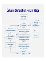
1.3—FLOWCHARTS
It is envisioned that the flowcharts herein will provide
the engineer with a simple reference to direct the design
process needed for each of the four SDCs.
Flowcharts outlining the steps in the seismic design
procedures implicit in these Guide Specifications are given
in Figures 1a to 6.
The Guide Specifications were developed to allow
three global seismic design strategies based on the
characteristics of the bridge system, which include:
•
Type 1—Design a ductile substructure with an
essentially elastic superstructure.
•
Type 2—Design an essentially elastic substructure
with a ductile superstructure.
•
Type 3—Design an elastic superstructure and
substructure with a fusing mechanism at the interface
between the superstructure and the substructure.
The flowchart in Figure 1a guides the designer on the
applicability of the Guide Specifications and the breadth of
the design procedure dealing with a single-span bridge
versus a multispan bridge and a bridge in SDC A versus a
bridge in SDC B, C, or D.
© 2009 by the American Association of State Highway and Transportation Officials.
All rights reserved. Duplication is a violation of applicable law.
SECTION 1: INTRODUCTION
1-5
Figure 1b shows the core flowchart of procedures
outlined for bridges in SDCs B, C, and D. Figure 2 outlines
the demand analysis. Figure 3 directs the designer to
determine displacement capacity. Figure 4 shows the
modeling procedure. Figures 5a and 5b establish member
detailing requirements based on the type of the structure
chosen for seismic resistance. Figure 6 shows the
foundation design.
© 2009 by the American Association of State Highway and Transportation Officials.
All rights reserved. Duplication is a violation of applicable law.
1-6
AASHTO GUIDE SPECIFICATIONS FOR LRFD SEISMIC BRIDGE DESIGN
Figure 1.3-1a—Seismic Design Procedure Flowchart
© 2009 by the American Association of State Highway and Transportation Officials.
All rights reserved. Duplication is a violation of applicable law.
SECTION 1: INTRODUCTION
1-7
Figure 1.3-1b—Seismic Design Procedure Flowchart
© 2009 by the American Association of State Highway and Transportation Officials.
All rights reserved. Duplication is a violation of applicable law.
1-8
AASHTO GUIDE SPECIFICATIONS FOR LRFD SEISMIC BRIDGE DESIGN
Figure 1.3-2—Demand Analysis Flowchart
© 2009 by the American Association of State Highway and Transportation Officials.
All rights reserved. Duplication is a violation of applicable law.
SECTION 1: INTRODUCTION
1-9
Figure 1.3-3—Displacement Capacity Flowchart
© 2009 by the American Association of State Highway and Transportation Officials.
All rights reserved. Duplication is a violation of applicable law.
1-10
AASHTO GUIDE SPECIFICATIONS FOR LRFD SEISMIC BRIDGE DESIGN
Figure 1.3-4—Modeling Procedure Flowchart
© 2009 by the American Association of State Highway and Transportation Officials.
All rights reserved. Duplication is a violation of applicable law.
SECTION 1: INTRODUCTION
1-11
Figure 1.3-5a—Detailing Procedure Flowchart
© 2009 by the American Association of State Highway and Transportation Officials.
All rights reserved. Duplication is a violation of applicable law.
1-12
AASHTO GUIDE SPECIFICATIONS FOR LRFD SEISMIC BRIDGE DESIGN
Figure 1.3-5b—Detailing Procedure Flowchart
© 2009 by the American Association of State Highway and Transportation Officials.
All rights reserved. Duplication is a violation of applicable law.
SECTION 1: INTRODUCTION
1-13
Figure 1.3-6—Foundation Design Flowchart
© 2009 by the American Association of State Highway and Transportation Officials.
All rights reserved. Duplication is a violation of applicable law.
SECTION 2: DEFINITIONS AND NOTATION
TABLE OF CONTENTS
2
2.1—DEFINITIONS..................................................................................................................................................... 2-1
2.2—NOTATION ......................................................................................................................................................... 2-2
2-i
© 2009 by the American Association of State Highway and Transportation Officials.
All rights reserved. Duplication is a violation of applicable law.
SECTION 2:
DEFINITIONS AND NOTATION
2.1—DEFINITIONS
Capacity Checks—Capacity design checks made with the overstrength magnifiers set to 1.0. The expected strengths of materials
are included. Capacity checks are permitted in lieu of full capacity design for SDC B.
Capacity Design—A method of component design that allows the designer to prevent damage in certain components by making
them strong enough to resist loads that are generated when adjacent components reach their overstrength capacity.
Capacity-Protected Element—Part of the structure that is either connected to a critical element or within its load path and that
is prevented from yielding by virtue of having the critical member limit the maximum force that can be transmitted to the
capacity-protected element.
Collateral Seismic Hazard—Seismic hazards other than direct ground shaking, such as liquefaction, fault rupture, etc.
Complete Quadratic Combination (CQC)—A statistical rule for combining modal responses from an earthquake load applied in
a single direction to obtain the maximum response due to this earthquake load.
Critical or Ductile Elements—Parts of the structure that are expected to absorb energy and undergo significant inelastic
deformations while maintaining their strength and stability.
Damage Level—A measure of seismic performance based on the amount of damage expected after one of the design
earthquakes.
Displacement Capacity Verification—A design and analysis procedure that requires the designer to verify that his or her
structure has sufficient displacement capacity. It generally involves the Nonlinear Static Procedure (NSP), also commonly
referred to as “pushover” analysis.
Ductile Substructure Elements—See Critical or Ductile Elements.
Earthquake-Resisting Element (ERE)—The individual components, such as columns, connections, bearings, joints, foundation,
and abutments, that together constitute the earthquake-resisting system (ERS).
Earthquake-Resisting System (ERS)—A system that provides a reliable and uninterrupted load path for transmitting seismically
induced forces into the ground and sufficient means of energy dissipation and/or restraint to reliably control seismically induced
displacements.
Life Safety Performance Level—The minimum acceptable level of seismic performance allowed by this Guide Specification;
intended to protect human life during and following a rare earthquake.
Liquefaction—Seismically induced loss of shear strength in loose, cohesionless soil that results from a buildup of pore water
pressure as the soil tries to consolidate when exposed to seismic vibrations.
Liquefaction-Induced Lateral Flow—Lateral displacement of relatively flat slopes that occurs under the combination of gravity
load and excess pore water pressure (without inertial loading from earthquake); often occurs after the cessation of earthquake
loading.
Liquefaction-Induced Lateral Spreading—Incremental displacement of a slope that occurs from the combined effects of pore
water pressure buildup, inertial loads from the earthquake, and gravity loads.
Local—Descriptor used to denote direction, displacement, and other response quantities for individual substructure locations.
Seismic analysis is performed “globally” on the entire structure, while evaluations are typically performed at the local level.
Minimum Support Width—The minimum prescribed length of a bearing seat that is required to be provided in a new bridge
designed according to this Guide Specification.
Nominal Resistance—Resistance of a member, connection, or structure based on the expected yield strength (Fye) or other
specified material properties, and the nominal dimensions and details of the final section(s) chosen, calculated with all material
resistance factors taken as 1.0.
2-1
© 2009 by the American Association of State Highway and Transportation Officials.
All rights reserved. Duplication is a violation of applicable law.