CircuitSwitching Networks
Bạn đang xem bản rút gọn của tài liệu. Xem và tải ngay bản đầy đủ của tài liệu tại đây (620.07 KB, 22 trang )
Chapter 4
Circuit-Switching
Networks
4.1 Multiplexing
4.2 SONET
Transport Networks
Circuit Switches
The Telephone Network
Signaling
Traffic and Overload Control in Telephone
Networks
Cellular Telephone Networks
Circuit Switching Networks
End-to-end dedicated circuits between clients
Circuit can take different forms
Dedicated path for the transfer of electrical current
Dedicated time slots for transfer of voice samples
Dedicated frames for transfer of Nx51.84 Mbps signals
Dedicated wavelengths for transfer of optical signals
Circuit switching networks require:
Client can be a person or equipment (router or switch)
Multiplexing & switching of circuits
Signaling & control for establishing circuits
These are the subjects covered in this chapter
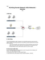
How a network grows
(a) A switch provides the network to a cluster of users, e.g.,
a telephone switch connects a local community
Network
Access
network
(b) A multiplexer connects two access networks, e.g., a high
speed line connects two switches
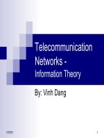
A Network Keeps Growing
1*
b
a
(a)
(b)
2
Metropolitan network A
viewed as Network A of
Access Subnetworks
a
4
3
A
A
c
d
Metropolitan
National network viewed
as Network of Regional
Subnetworks (including A)
b
d
c
Network of
Access
Subnetworks
A
Very
highspeed lines
α
Network of Regional
Subnetworks
National &
International
Chapter 4
Circuit-Switching
Networks
4.1 Multiplexing
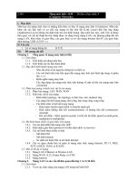
Multiplexing
Multiplexing involves the sharing of a transmission channel
(resource) by several connections or information flows
Significant economies of scale can be achieved by combining
many signals into one
Channel = 1 wire, 1 optical fiber, or 1 frequency band
Fewer wires/pole; a fiber replaces thousands of cables
Implicit or explicit information is required to demultiplex the
information flows.
(a)
Shared
Channel
(b)
A
A
A
B
B
B
C
C
C
MUX
MUX
A
B
C
Frequency-Division Multiplexing
A channel divided into frequency slots
A
0
(a) Individual
signals occupy
Wu Hz
f
Wu
B
0
f
Wu
C
(b) Combined
signal fits into
channel
bandwidth
f
Wu
0
A
0
B
C
W
f
Guard bands
required
AM or FM radio
stations
TV stations in
air or cable
Analog
telephone
systems
Time-Division Multiplexing
High-speed digital channel divided into time slots
A1
A2
0T
…
t
6T
3T
(a) Each signal
transmits 1 unit
every 3T
seconds
B1
B2
C1
C2
0T
(b) Combined
signal transmits
1 unit every T
seconds
0T
B1
1T 2T
C1
A2
3T 4T
…
t
6T
3T
A1
t
6T
3T
0T
…
B2
C2
5T 6T
…
t
Framing
required
Telephone
digital
transmission
Digital
transmission in
backbone
network
T-Carrier System
Digital telephone system uses TDM.
PCM voice channel is basic unit for TDM
1 channel = 8 bits/sample x 8000 samples/sec. = 64 kbps
T-1 carrier carries Digital Signal 1 (DS-1) that
combines 24 voice channels into a digital stream:
1
...
2
24
1
MUX
MUX
22
23
24
b
1
2
...
24
b
Frame
2
...
24
Framing bit
Bit Rate = 8000 frames/sec. x (1 + 8 x 24) bits/frame
= 1.544 Mbps
North American Digital
Multiplexing Hierarchy
1
24
.
.
DS1 signal, 1.544Mbps
Mux
24 DS0
1
4 DS1
4
.
.
DS2 signal, 6.312Mbps
Mux
1
7 DS2
7
.
.
DS3 signal, 44.736Mpbs
Mux
1
DS0,
DS1,
DS2,
DS3,
DS4,
64 Kbps channel
1.544 Mbps channel
6.312 Mbps channel
44.736 Mbps channel
274.176 Mbps channel
6 DS3
6
.
.
Mux
DS4 signal
274.176Mbps
CCITT Digital Hierarchy
CCITT digital hierarchy based on 30 PCM channels
1
30
.
.
64 Kbps
2.048 Mbps
Mux
1
4
.
.
8.448 Mbps
Mux
1
E1,
E2,
E3,
E4,
2.048 Mbps channel
8.448 Mbps channel
34.368 Mbps channel
139.264 Mbps channel
..
34.368 Mpbs
Mux
139.264 Mbps
1
4
.
.
Mux
Clock Synch & Bit Slips
Digital streams cannot be kept perfectly synchronized
Bit slips can occur in multiplexers
Slow clock results in late bit
arrival and bit slip
MUX
5
4
3
2
1
t
5
4
3
2
1
Pulse Stuffing
Pulse Stuffing: synchronization to avoid data loss due to bit slips
Output rate > R1+R2
i.e. DS2, 6.312Mbps=4x1.544Mbps + 136 Kbps
Pulse stuffing format
Fixed-length master frames with each channel allowed to stuff or not
to stuff a single bit in the master frame.
Redundant stuffing specifications
signaling or specification bits (other than data bits) are distributed
across a master frame.
Muxing of equal-rate signals
requires perfect synch
Pulse stuffing
Wavelength-Division Multiplexing
Optical fiber link carries several wavelengths
From few (4-8) to many (64-160) wavelengths per fiber
Imagine prism combining different colors into single beam
Each wavelength carries a high-speed stream
Each wavelength can carry different format signal
e.g., 1 Gbps, 2.5 Gbps, or 10 Gbps
λ1
λ2
λm
Optical
deMUX
Optical
MUX
λ1 λ
2.
λm
Optical
fiber
λ1
λ2
λm
Example: WDM with 16 wavelengths
30 dB
1560 nm
1550 nm
1540 nm
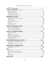
Typical U.S. Optical Long-Haul
Network
Chapter 4
Circuit-Switching
Networks
4.2 SONET
SONET: Overview
Synchronous Optical NETwork
North American TDM physical layer standard for
optical fiber communications
8000 frames/sec. (Tframe = 125 µsec)
SDH (Synchronous Digital Hierarchy) elsewhere
compatible with North American digital hierarchy
Needs to carry E1 and E3 signals
Compatible with SONET at higher speeds
Greatly simplifies multiplexing in network backbone
OA&M support to facilitate network management
Protection & restoration
SONET simplifies multiplexing
Pre-SONET multiplexing: Pulse stuffing required demultiplexing
all channels
MUX
DEMUX
Remove
tributary
MUX
DEMUX
Insert
tributary
SONET Add-Drop Multiplexing: Allows taking individual channels in
and out without full demultiplexing
MUX
DEMUX
ADM
Remove
tributary
Insert
tributary
SONET Specifications
Defines electrical & optical signal interfaces
Electrical
Multiplexing, Regeneration performed in electrical
domain
STS – Synchronous Transport Signals defined
Very short range (e.g., within a switch)
Optical
Transmission carried out in optical domain
Optical transmitter & receiver
OC – Optical Carrier
SONET & SDH Hierarchy
SONET Electrical
Signal
Optical Signal
Bit Rate (Mbps)
SDH
Electrical Signal
STS-1
OC-1
51.84
N/A
STS-3
OC-3
155.52
STM-1
STS-9
OC-9
466.56
STM-3
STS-12
OC-12
622.08
STM-4
STS-18
OC-18
933.12
STM-6
STS-24
OC-24
1244.16
STM-8
STS-36
OC-36
1866.24
STM-12
STS-48
OC-48
2488.32
STM-16
STS-192
OC-192
9953.28
STM-64
STS: Synchronous
Transport Signal
OC: Optical Channel
STM: Synchronous
Transfer Module
SONET Multiplexing
DS2
E1
DS3
...
44.736
E4
139.264
ATM or
POS
Low-speed
mapping
function
Medium
speed
mapping
function
Highspeed
mapping
function
Highspeed
mapping
function
STS-1
51.84 Mbps
STS-1
STS-1
STS-1
STS-1
STS-1
STS-1
STS-1
OC-n
STS-n
...
DS1
STS-3c
STS-3c
Scrambler
MUX
E/O