Sổ tay môi chất lạnh
Bạn đang xem bản rút gọn của tài liệu. Xem và tải ngay bản đầy đủ của tài liệu tại đây (3.16 MB, 267 trang )
Executive Summary
EXECUTIVE SUMMARY
This Refrigerant Management Handbook (Handbook) includes everything the base civil
engineer (BCE) needs to develop a Base Refrigerant Management Program (BRMP). The
BRMP will help the BCE manage refrigerants that have a damaging effect on the ozone
layer. These are part of a class of substances called ozone-depleting chemicals (ODC). They
must be controlled to eliminate their dispersion into the atmosphere.
The policies and regulations that support the reduction of ozone depletion require the BCE to
carefully control refrigerants and monitor air conditioning/refrigeration (AC/R) equipment.
These policies are:
The Montreal Protocol and subsequent amendments that placed a worldwide ban on
the production of chlorofluorocarbon (CFC) and hydrochlorofluorocarbon (HCFC)
refrigerants starting in 1996 and 2031, respectively.
The Environmental Protection Agency (EPA) regulation issued in May 1993 to
minimize CFC, HCFC and, starting on 15 November 1995, hydrofluorocarbon (HFC)
emissions during operations, maintenance, repair, and disposal of refrigerant-using
equipment.
The Secretary and Chief of Staff of the Air Force Action Memorandum, date
7 January 1993, which prohibits the purchase of any CFC refrigerants and AC/R
equipment which use these refrigerants starting in June 1993. Exceptions are approved
only by an Air Staff waiver.
To effectively manage AC/R equipment and regulated refrigerants, the BRMP, through the
base Refrigerant Manager (RM), focuses on conservation measures and the development of a
Refrigerant Management Plan (RMP). The conservation measures will help the BCE meet the
EPA requirements of minimal releases of refrigerant through improved servicing techniques,
training and certifying technicians, and recording equipment maintenance and refrigerant
usage. The RMP provides a plan to ensure adequate refrigerant supplies will be available to
meet mission needs until the last of the units using CFC refrigerants have achieved their full
economic life. The RMP provides a refrigerant inventory timeline that shows refrigerant
consumption rates, equipment retirements, and other activities which affect the inventory of
refrigerant. An implementation schedule is part of the RMP. Its purpose is to assist in
keeping equipment retirement on schedule. A simple comparison of a plan’s projected
refrigerant inventory quantity versus what is actually on-hand will tell the BCE whether the
base is meeting its goals or is in danger of a negative mission impact.
iii
Executive Summary
The Handbook includes all the information the RM needs to initiate and carry out a BRMP.
The Handbook’s appendices cover the:
National and Air Force policies on ODC refrigerants,
● technical criteria for mechanical room design to support alternative refrigerants,
● procedures for making a retrofit or replacement decision using life-cycle cost analysis,
● methods to correctly size a replacement chiller or justify a central plant,
● use of the Work Information Management System (WIMS) software for tracking refrigerant usage and equipment maintenance,
● various types of funding available to pay for new conservation equipment and AC/R
units, and
● conservation techniques for following EPA requirements.
●
This Handbook represents the Air Force’s resolve to protect the environment while meeting
its global mission. As stated in the Secretary and Chief of Staff of the Air Force Action
Memorandum:
“The sooner we learn to live without these substances, the less likely we are to suffer a
mission stoppage because they are not available, and the less we will contribute to the
depletion of the earth’s ozone layer. ”
iv
Table of Contents
Table of Contents
Page
Section
Chapter l Introduction . . . . . . . . . . . . . . . . . . . . . . . . . .
1.1 Background . . . . . . . . . . . . . . . . . . . . . . . . . .
1.1.1 Refrigerant Management Required . . . . . . . . . . . . . . .
1.1.2 CFCs and HCFCs - Class I and Class II Refrigerants . . . . . . .
1.2 Air Force Goal . . . . . . . . . . . . . . . . . . . . . . . . . .
1.3 The Base Refrigerant Management Program . . . . . . . . . . . . . .
1.4 Handbook Organization . . . . . . . . . . . . . . . . . . . . . .
l.4.1 BRMP Elements . . . . . . . . . . . . . . . . . . . . .
l.4.2 Appendix Summary . . . . . . . . . . . . . . . . . . . . .
1.5 The Refrigerant Manager . . . . . . . . . . . . . . . . . . . . . .
1.5.1 RM’s Responsibilities . . . . . . . . . . . . . . . . . . . .
1.5.2 RM’s Capabilities . . . . . . . . . . . . . . . . . . . . . .
Chapter 2 Conservation Efforts for the Base Refrigerant Management Program .
2.1 Introduction . . . . . . . . . . . . . . . . . . . . . . . . .
2.2 EPA Requirements . . . . . . . . . . . . . . . . . . . . . .
2.2.1 Equipment Servicing and Repairs . . . . . . . . . . . . .
2.2.2 EPA Maximum Leak Rates . . . . . . . . . . . . . . . .
2.3 Air Force Requirements . . . . . . . . . . . . . . . . . . . .
2.3.1 Managing Base Refrigerants . . . . . . . . . . . . . . .
2.4 Training and Certification . . . . . . . . . . . . . . . . . . . .
2.4.1 CerTest Module . . . . . . . . . . . . . . . . . . . .
2.4.2 Local Vendors . . . . . . . . . . . . . . . . . . . . .
2.5 BCE Conservation Methods . . . . . . . . . . . . . . . . . . .
2.5.1 Leak Detection . . . . . . . . . . . . . . . . . . . . .
2.5.2 AC/R Equipment Modifications . . . . . . . . . . . . . .
2.5.3 WIMS Refrigerant Management Software . . . . . . . . . .
2.5.4 Secure Storage Areas . . . . . . . . . . . . . . . . . .
Chapter
3.1
3.2
3.3
3.4
3.5
1-1
1-1
1-1
1-1
1-1
1-2
1-2
1-2
1-2
1-4
1-5
1-5
....
. .
. .
. .
. .
. .
. .
. .
. .
. .
. .
. .
. .
. .
. .
.2-1
2-1
2-1
2-1
2-2
2-2
2-2
2-3
2-3
2-3
2-3
2-3
2-3
2-4
2-4
3 Refrigerant Management Plan Development . . . . . . . . . . . . . .
Introduction . . . . . . . . . . . . . . . . . . . . . . . . . . .
RMP Development Procedures . . . . . . . . . . . . . . . . . . .
RMP Products . . . . . . . . . . . . . . . . . . . . . . . . .
Metrics . . . . . . . . . . . . . . . . . . . . . . . . . . . . .
Step l: Equipment Survey . . . . . . . . . . . . . . . . . . . . .
3.5.l Survey Results: . . . . . . . . . . . . . . . . . . . . . .
3-1
3-1
3-1
3-1
3-1
3-2
3-2
v
Table of Contents
Page
Section
3.6 Step 2: Equipment List.... . . . . . . . . . . . . . . . . . . .
3.6.1 Equipment List Completion . . . . . . . . . . . . . . . . .
3.7 Step 3: Equipment Assessment Table . . . . . . . . . . . . . . . . .
3.7.1 Value Determinations . . . . . . . . . . . . . . . . . . . .
3.7.2 Subjective Considerations . . . . . . . . . . . . . . . . . .
3.7.3 Method of Replacement . . . . . . . . . . . . . . . . . .
3.8 Step 4: Equipment Retirement Schedule and Refrigerant
Inventory Timeline . . . . . . . . . . . . . . . . . . .
3.8.1 Definition of Terms . . . . . . . . . . . . . . . . .
3.8.2 Developing the Equipment Retirement Schedule . . . . . . . . .
3.8.3 Refrigerant Inventory Tlmeline . . . . . . . . . . . . . . . .
3.9 Step 5: Project List and Funding Bar Chart . . . . . . . . . . . . . .
3.9.1 Project List . . . . . . . . . . . . . . . . . . . . . . .
3.9.2 Funding Bar Chart . . . . . . . . . . . . . . . . . . . . .
3.9.3 Funding Bar Chart Analysis . . . . . . . . . . . . . . . . .
3.10 Step 6: The Implementation Schedule . . . . . . . . . . . . . . . . .
3.10.1 Time Lengths . . . . . . . . . . . . . . . . . . . . . . .
3.11 Step 7: The RMP . . . . . . . . . . . . . . . . . . . . . . . . .
Chapter 4 Refrigerant Management Plan Implementation . . . . . . . .
4.1 The Philosophy . . . . . . . . . . . . . . . . . . . . .
4.2 Overview of System Selection . . . . . . . . . . . . . .
4.3 System Selection . . . . . . . . . . . . . . . . . . . .
4.3.1 Step 1: Cooling Load Analysis . . . . . . . . . . .
4.3.2 Step 2: Retrofit vs Replacement . . . . . . . . . . .
4.3.3 Step 3: Replacement Unit Selection . . . . . . . . .
4.3.4 Step 4: Installing a Central Plant . . . . . . . . . .
4.3.5 Step 5: Heat Recovery and Thermal Storage Technologies
4.4 System Selection Resources . . . . . . . . . . . . . . . .
4.4.1 Personnel . . . . . . . . . . . . . . . . . . . .
4.4.2 Tame . . . . . . . . . . . . . . . .
4.4.3 Technical References . . . . . . . . . . . . . . .
4.5 Importance of fending . . . . . . . . . . . . . . . . . .
. . . . .
.
.
.
.
.
.
.
.
.
.
.
.
.
.
.
.
.
.
.
.
.
.
.
.
.
.
.
.
.
.
.
.
. .
. .
. .
.
.
.
.
.
.
.
.
.
.
.
.
.
.
.
.
.
.
.
.
.
.
.
.
.
.
3-2
3-2
3-4
3-4
3-4
3-6
3-6
3-6
3-10
3-12
3-13
3-14
3-14
3-14
3-14
3-14
3-18
4-1
4-1
4-1
4-1
4-1
4-1
4-1
4-2
4-2
4-2
4-2
4-2
4-3
4-3
Appendix A Update on Refrigerants: Translating the Laws, Regulations, and
Policies into Practice . . . . . . . . . . . . . . . . . . . . A-1
Appendix B Refrigerant Sensors and Monitoring of Equipment Rooms . . . . . . B-1
Appendix C Refrigerant Storage Recommendations and Requirements . . . . . . . C-1
Appendix D Refrigerant Leak Detection Methods and Equipment . . . . . . . . . . D-1
vi
Table of Contents
Page
Section
Appendix E
Appendix F
Appendix G
Appendix H
Appendix I
Appendix J
Appendix K
Appendix L
Appendix M
Appendix N
Appendix O
Appendix P
Appendix Q
Appendix R
Equipment to Reduce Refrigerant Release During
Maintenance and Operation of Air Conditioning and
Refrigeration Systems . . . . . . . . . . . . . . . . . . . . E-1
Refrigerant Leak Mitigation through Equipment Maintenance
and Service Practices . . . . . . . . . . . . . . . . . . . . F-1
AFCESA Work Information Management System (WIMS)
Software Release 940715 . . . . . . . . . . . . . . . . G-1
AC/R Equipment Survey Guide and Equipment Data Collection
Survey Forms . . . . . . . . . . . . . . . . . . . . . . .. H-1
Funding Alternatives for Base Refrigerant Management Program . . . . 1-1
Application of ASHRAE Equipment Room Design Requirements . . . J-1
AC/R Energy Conservation Devices . . . . . . . . . . . . . . . K-1
Fundamentals of Cooling Load and Energy Analysis . . . . . . . . . L-1
Evaluating Water Chillers for Replacement or Retrofit Potential . . . . M-1
Chiller Selection Guide . . . . . . . . . . . . . . . . . . . . N-1
Assessing the Potential of Central Chilled Water Plants . . . . . . . . O-1
Heat Recovery Alternatives for Refrigerant Chillers . . . . . . . . . P-1
Assessing the Potential of Thermal Energy Storage . . . . . . . . . Q-1
Glossary of Terms and Definitions and Bibliography . . . . . . . . . R-1
List of Figures
Page
Figure
Figure 1-1
Figure 3-1
Figure 3-2
Figure 3-3
Figure 3-4
Figure 3-5
Figure 3-6
Figure 3-7
Figure 3-8
Refrigerant Management Handbook Flowchart . . . . . . . . . . .
Sample Completed Equipment List . . . . . . . . . . . . . . . .
Sample Completed Equipment Assessment Table . . . . . . . . . .
Sample Completed Equipment Retirement Schedule . . . . . . . . .
Sample Completed Equipment Refrigerant Inventory Tlmeline . . . . .
Sample Completed Project List . . . . . . . . . . . . . . . . .
Sample Completed Funding Bar Chart . . . . . . . . . . . . . .
Sample Completed Implementation Schedule . ., . . . . . . . . . .
Sample of Table of Contents . . . . . . . . . . . . . . . . . .
1-3
3-3
3-5
3-7
3-8
3-15
3-16
3-17
3-19
vii (viii-Blank)
(This Page Intentionally Blank)
Chapter 1 — Introduction
Chapter 1 — Introduction
1.1 Background
Refrigerants: Translating the Laws, Regulations, and Policies into Practice).
1.1.1 Refrigerant Management
Required
The Air Force Civil Engineer directed the
Air Force Civil Engineer Support Agency
(AFCESA) to develop base guidance for
managing refrigerant inventories to ensure
all air conditioning and refrigeration
(AC/R) equipment operates until the end
of its economic life. This requirement was
in the Action Memorandum, 7 January
1993, from the Secretary and Chief of
Staff of the Air Force implementing the
Air Force ozone-depleting chemicals
(ODC) policy. The memorandum was a
direct result of the worldwide movement to
reduce ODCS, including production bans
starting in January 1996.
1.2 Air Force Goal
1.1.2 CFCS and HCFCs - Class I and
Class II Refrigerants
Chlorofluorocarbons (CFCs) and hydrochlorofluorocarbons (HCFC) are ODCs
and are categorized as Class I and II refrigerants, respectively. The Environmental Protection Agency (EPA) published
regulation 40 C.F.R. Part 82 (1993) to
minimize Class I and 11 emissions during
operations, maintenance, repair, and disposal of refrigerant-using equipment. The
regulation applies to persons who work
on this equipment as well as refrigerant
reclaimers, equipment owners, and refrigerant recycling and recovery equipment.
The EPA may levy stiff fines for noncompliance (See Appendix A, Update on
The Air Force goal is to manage the
inventory of regulated refrigerants and
AC/R equipment to ensure uninterrupted
mission support while operating this
equipment until the end of its economic
life. The maintenance procedures used by
base civil engineer (BCE) personnel must
be compatible with the EPA’s environmental compliance regulations. The Refrigerant
Management Handbook’s (Handbook)
objective is to make each base self-sufficient in CFC refrigerants. It assists the
BCE in developing a Base Refrigerant
Management Program (BRMP) to manage
refrigerant resources and operate AC/R
equipment to ensure continued mission
support and environmental compliance.
Using strong conservation procedures and
life-cycle costing methods, the BRMP will
extend the availability of the existing
refrigerant supplies and prioritize equipment retirements. Although the emphasis
is on CFCs and HCFCs, the Handbook’s
procedures to standardize operation and
maintenance practices should be applied to
all refrigerants. It is also intended the
Handbook be used by the base refrigerant
manager (RM) in developing the Refrigerant Management Plan (RMP). Following
the guidelines provided in the text and
appendices, the RM will be able to successfully complete all essential elements of
the RMP.
1-1
Chapter 1 — Introduction
1.3 The Base Refrigerant
Management Program
The BRMP implements refrigerant conservation procedures and develops a base
RMP that prioritizes AC/R equipment
retirements. The RMP includes graphs and
tables to predict the rate of refrigerant
consumption, schedule equipment retirements, and identify the need for refrigerant
to prevent negative mission impacts. The
RMP will ensure the availability of adequate refrigerant supplies through the
remaining life of existing equipment. It
must be updated periodically to accurately
reflect the changes in funding and mission.
1.4 Handbook Organization
The Handbook contains four chapters that
describe how to establish the BRMP. The
appendices supplement the chapters on
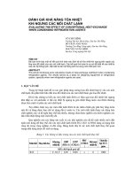
specific technical topics. Figure 1-1,
Refrigerant Management Handbook FlOWchart, shows the relationship between
chapters and appendices. The flowchart,
highlighting the applicable chapter and
appendices, also appears at the beginning
of each chapter.
1.4.1 BRMP Elements
The Handbook separates the BRMP into
two elements:
● recommendations to reduce refrigerant
consumption and meet EPA requirements, and
● the development and implementation of
the base RMP.
1.4.1.1 The first element, discussed in
Chapter 2, Conservation Efforts for the
1-2
Base Refrigerant Management Program,
contains a set of recommended actions to
reduce refrigerant consumption and help
the BCE meet EPA requirements such as:
● releasing minimal amounts of CFC and
HCFC refrigerants into the
atmosphere,
● practicing refrigerant conservation
servicing techniques,
● training and certifying technicians to
handle refrigerants,
● recording equipment maintenance and
refrigerant usage, and
● controlling refrigerant inventory.
Integral to recording and controlling refrigerant is the use of the Work Information Management System (WIMS) and
WIMS Refrigerant Management Software.
1.4.1.2 The second element of the BRMP
is addressed in Chapter 3, Refrigerant
Management Plan Development, and Chapter 4, Refrigerant Management Plan Implementation. The RMP will help the base
manage its regulated refrigerants and the
AC/R equipment that uses those refrigerants. The RMP requires engineering and
life-cycle cost analyses to determine if a
unit should be retrofitted to a non-CFC
refrigerant, replaced in kind, or replaced
with another type of equipment or process
(such as a central plant or absorption unit).
1.4.2 Appendix Summary
Following is a summary of each appendix.
Appendix A – details of applicable requirements of the Clean Air Act Amendments or CAAA, Title VI, and Air Force
Policies to implement them;
Chapter 1 — Introduction
Figure 1-1. Refrigerant Management Handbook Flowchart
1-3
Chapter 1 — Introduction
Appendix B — descriptions, availability,
and applications of refrigerant area monitors for use in mechanical rooms and
refrigerant storage areas;
Appendix C — refrigerant storage requirements for facilities and containers and safe
handling of refrigerants;
Appendix D — refrigerant leak detection
methods and equipment for high- and lowpressure refrigerants when the equipment
is operating or idle, advantages and disadvantages of portable units that pinpoint
leak locations, common equipment leak
locations;
Appendix E — terms and reviews of
equipment used for recovery, recycling,
and reclamation;
Appendix F — major changes to refrigerant leak mitigation procedures during
equipment servicing practices that will
meet EPA requirements and recommendations;
Appendix G — how the WIMS Refrigerant Management Software helps the RM
monitor AC/R equipment and refrigerant
usage;
Appendix H — how to perform an Equipment Survey, providing the tools and
personnel requirements and a line-by-line
explanation of the equipment survey
forms;
Appendix I — different funding avenues
that can pay for refrigerant conservation
equipment and AC/R equipment retirement
projects, including criteria and examples of
programming documents;
Appendix J — mechanical equipment
room design requirements for refrigeration
systems in ASHRAE 15-1992, RefrigerantQuality Rule 4;
Appendix K — use of energy conservation
devices for AC/R equipment;
1-4
Appendix L – calculations for a building’s cooling load and energy usage
analysis (Appendices L, M, N, O, P, and
Q have a distinct relationship in the selection process. This relationship is shown
graphically on the back of the tab of each
appendix);
Appendix M — procedures and guidelines
for evaluating replacement and retrofit
options for existing water chillers by comparing life-cycle costs taking into consideration age, mechanical condition, operating
efficiency, and criticality to the building(s)
or system(s) they serve;
Appendix N — guidelines and procedures
to select water chillers based on efficiency,
availability of fuel sources, load matching,
initial cost, and annual operating cost;
Appendix O — guidelines for determining
the potential to replace several individual
chillers with a central plant that can be a
combination of retrofitted and new chillers
in a new structure or an expanded, existing
mechanical room;
Appendix P — guidelines for determining
when heat recovery chillers may be economically feasible by comparing the lifecycle cost of the alternatives;
Appendix Q — guidelines for determining
when thermal energy storage systems
(TESS) may be an economically feasible
alternative for integration into an existing
or proposed chilled water system; and
Appendix R — glossary of terms and
definitions, and bibliography.
1.5 The Refrigerant Manager
The BRMP will be developed by the BCEappointed RM. This Handbook provides
Chapter 1 — Introduction
the RM with the background, tools, and
methods needed to manage the base refrigerant and equipment resources. The RM
has several responsibilities and must
possess certain capabilities in order to
accomplish the job.
1.5.1 RM’s Responsibilities
The RM must track:
●
●
●
●
●
●
refrigerant consumption by each piece
of equipment,
base refrigerant inventory levels,
consumption rates for each type of
refrigerant,
project cost and schedule for equipment
retirement,
equipment service records and maintenance and repair requirements, and
the status of the AC/R technicians’
training and certification.
1.5.2 RM’s Capabilities
The RM must:
● be familiar with the WIMS Refrigerant
Management Software,
● be able to use various spreadsheet and
graphics software,
● have a working knowledge of the EPA
requirements governing the use of
regulated refrigerants,
● be able to do life-cycle cost and cooling load analysis on AC/R equipment,
and
● understand procedures to justify different types of funding.
A team whose members share these capabilities and have access to other talent in
the BCE organization can perform the
RM’s responsibilities. A possible duty
location for the RM is in Maintenance
Engineering.
1-5 (1-6 Blank)
(This Page Intentionally Blank)
Chapter 2 – Conservation Efforts for the Base Refrigerant Management Program
Chapter 2 — Conservation Efforts for the
Base Refrigerant Management Program
2.1 Introduction
This chapter provides information and
recommendations on refrigerant conservation that will aid the RM in establishing
the BRMP. The information and recommendations will help the RM comply with
the EPA and Air Force requirements that
pertain to both CFC and HCFC refrigerants.
2.2 EPA Requirements
2.2.1 Equipment Servicing and Repairs
Detailed requirements and information on
accomplishing equipment servicing and
repairs are found in Appendix E, Equipment to Reduce Refrigerant Release During
Maintenance and Operation of Air Conditioning and Refrigeration Systems, and
Appendix F, Refrigerant Leak Mitigation
through Equipment Maintenance and Service Practices.
2.2.1.1 Technicians must be EPA certified by 14 November 1994 to service
AC/R equipment using CFC and HCFC
refrigerants.
2.2.1.2 Since 1 July 1992, no one could
knowingly release CFC or HCFC refrigerants into the atmosphere. This will apply
to hydrofluorocarbons (HFC) refrigerants
starting 15 November 1995.
2.2.1.3 Anyone who disposes of AC/R
equipment must recover the remaining
refrigerant and/or verify that the refrigerant has been evacuated from the equipment.
2.2.1.4 Personnel who maintain, repair,
or dispose of AC/R equipment must certify
their recovery and recycling equipment to
EPA.
2.2.1.5 Operators of equipment containing
50 or more pounds of CFC- and HCFCregulated refrigerants must keep up-to-date
service records for the previous three
years showing date, type of service, and
quantity of refrigerant added-and purchased.
2.2.1.6 Commercial refrigeration equipment with over 50 pounds of refrigerant
(that is, cold storage plants) must be repaired of all leaks within 30 days if the
equipment is leaking at a rate which will
exceed 35 percent of the total charge
during a 12-month period.
2.2.1.7 Equipment, other than commercial refrigeration, containing 50 or more
pounds of refrigerant (that is, comfort
cooling) must be repaired of all leaks
within 30 days if the unit leaks at a rate
exceeding 15 percent of the total charge
during a 12-month period.
2.2.1.8 Equipment does not require repair
if, within 30 days after leak identification
(as described in 2.2.1.6 and 2.2.1.7), a
plan is developed for retirement of that
equipment within one year. A copy of the
retirement plan must be available at the
site of the equipment.
2-1
Chapter 2 – Conservation Efforts for the Base Refrigerant Management Program
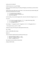
2.2.2 EPA Maximum Leak Rates
The following example shows how to
calculate the EPA maximum leak rates.
This rate is shown in the WIMS Refrigerant Consumption Rates - by Facility, Equipment, and Service Date report (see
Appendix G, Work Information Management System (W7MS)).
EXAMPLE
An office building is cooled by a 200-ton centrifugal chiller with an 800-pound CFC-12 refrigerant
charge. Fifteen pounds of CFC-12 were added
during the last servicing. Because the chiller provides comfort cooling and has more than 50 pounds
of charge, use the 15 percent leak rate. (If this
were a commercial refrigerant system, the 35 percent leak rate would apply. )
Service Records
Service Dates
Calendar Date Julian Date
274
1 October
338
4 December
Refrigerant Added
10 lb
15 lb
1. Determine the EPA Maximum Leak Rate
(EPAMLR):
EPAMLR = 800 lb x 15%/yr = 120 lb/yr
(This is the maximum amount of refrigerant
this unit can lose in a 12-month period
without violating the EPA regulation.)
2. Determine the actual leak rate (ALR):
ALR = lb refrigerant added since last servicing
(Days between servicing)/(365 days/yr)
ALR =
15 lb of CFC-12
(338-274 days)/(365 days/yr)
ALR = 85 lb/yr
2-2
3. Is ALR > EPAMLR?
85 lb/yr is less than 120 lb/yr
Action is NOT necessary. However, the unit
did use 15 pounds of refrigerant. Good conservation practice recommends performing a
leak check and repairing the leak.
If the ALR had been > EPAMLR, then the
equipment would have to be repaired in 30 days
or a plan developed within 30 days to retire the
unit within 12 months.
2.3 Air Force Requirements
2.3.1 Managing Base Refrigerants
Air Force policy governing the use of
CFC refrigerants has dictated the following
requirements.
2.3.1.1 An Air Force waiver is required
to purchase CFC refrigerants.
2.3.1.2 Purchasing new facility air conditioning systems that use CFCs is prohibited.
2.3.1.3 Manage the base’s refrigerant
inventory so existing equipment can be
maintained until the end of its economic
life.
2.3.1.4 When AC/R equipment is retired,
its refrigerant must be recovered for use in
the remaining operational systems.
2.3.1.5 Refrigerant ownership cannot
be sold or transferred outside of the
Department of Defense (DoD). Transfer
of excess refrigerant to other bases is
Chapter 2 – Conservation Efforts for the Base Refrigerant Management Program
encouraged and should be coordinated
through the Major Command (MAJCOM).
If refrigerant is to be turned in to the
Defense Logistics Agency (DLA) Refrigerant Bank, it should first be coordinated
through the MAJCOM.
2.4 Training and Certification
All technicians who work with refrigerant
must meet EPA certification requirements.
The EPA deadline is 14 November 1994.
Training and certification sessions include
improved maintenance practices, identification of potential improvements to existing AC/R equipment, and familiarization
with new equipment. There are two ways
the RM can obtain training and certification opportunities for technicians.
2.4.1 CerTest Module
AFCESA Maintenance Directorate and the
Civil Engineering School (School) at
Sheppard AFB, Texas developed a
100-page study guide and a Certification
Test (CerTest) module for EPA certification. All Air Force technicians will be
able to review the guide and take the
certification test at their home stations.
The School is approved by EPA to certify
technicians.
2.4.2 Local Vendors
The RM can contract with local vendors
for refrigeration training and EPA certification. The RM must verify EPA has
approved the vendor as a certifying agent.
Depending on availability, both Operations
and Maintenance and Pollution Prevention
Program funds can be used for buying
training and certification testing.
2.5 BCE Conservation Methods
In considering the base’s conservation
effort, the RM should take into account
leak detection, AC/R equipment modification, and secure storage areas for refrigerant.
2.5.1 Leak Detection
The RM should develop a leak detection
program that matches each piece of AC/R
equipment with a specific type of leak
detection. The RM should also develop an
equipment leak check schedule based on
the type of equipment and its past leak
history. The greater the equipment’s history of leaks, the more frequently it should
be checked.
2.5.1.1 Leak detection procedures vary
from soap bubbles to sophisticated sensors.
Some of the leak detection equipment
items qualify for Pollution Prevention
Funds. For detailed information, review
Appendix D, Refrigerant Leak Detection
Methods and Equipment; Appendix F,
Refrigerant Leak Mitigation through
Equipment Maintenance and Service Practices; and Appendix I, Funding Alternatives for Base Refrigerant Management
Program.
2.5.2 AC/R Equipment Modifications
Several equipment modifications can be
used to prevent excessive amounts of
refrigerant from escaping into the atmosphere. For example, the RM should
identify all requirements for high-efficiency purge units and pressurization systems
for low-pressure equipment. More information is available in Appendix E.
2-3
Chapter 2 — Conservation Efforts for the Base Refrigerate Management Program
Pollution prevention funds can provide a
resource to pay for equipment modifications (see Appendix I).
2.5.3 WIMS Refrigerant Management
Software
To develop a successful conservation
effort, the RM must control refrigerant
when it is not in equipment and identify
equipment exceeding the EPA maximum
leak rate. To help the RM with refrigerant
and equipment control, AFCESA developed the WIMS Refrigerant Management
Software. Appendix G covers the subject
extensively. The software files contain all
the data for the base’s AC/R equipment
and refrigerant inventory. With regular
input of equipment service records and
inventory transactions into WIMS software
files, the RIM can generate reports showing
2-4
which pieces of equipment are not in
compliance and the amount of refrigerant
in storage. Regular data entry will satisfy
the EPA recordkeeping requirement.
2.5.4 Secure Storage Areas
Because refrigerant is a valuable and diminishing resource, the base should have
one or more secure storage areas. Mechanical rooms do not qualify. The RM
should establish storage location(s) based
on ease of accessibility for technicians and
positive control of the resource. This could
mean designating one or more people to be
responsible for the distribution and accounting of the refrigerant. For information on storage room construction standards see Appendix C, Refrigerant Storage
Recommendations and Requirements.
Chapter 3 — Refrigerant Management Plan Development
Chapter 3 — Refrigerant Management Plan Development
3.1 Introduction
3.3 RMP Products
This chapter describes how to develop an
RMP for all AC/R equipment which use
regulated refrigerants. A plan should first
be developed for managing equipment
which use CFC refrigerants because CFC
production will cease in January 1996.
Eventually, an RMP needs to be developed
for all equipment containing regulated
refrigerants. Appendix H, AC/R Equipment
Survey Guide and Equipment Data Collection Survey Forms, is integral to the
development of the RMP.
The seven main products in the RMP are
the:
● Equipment List,
● Equipment Assessment Table,
● Equipment Retirement Schedule,
● Refrigerant Inventory Timeline,
● Project List,
● Funding Chart, and
● Implementation Schedule.
Together these products give the total
picture of how refrigerants are managed at
the base by showing all equipment retirements, what they cost, when more refrigerant will be needed, and increases of
refrigerant inventory by recovery, purchases, or interbase transfers. They highlight
the effects of conservation efforts on the
refrigerant consumption rates.
3.2 RMP Development
Procedures
The RMP development begins with a
thorough physical survey and assessment
of the condition of all equipment. From
the survey and assessment, a prioritized
Equipment Retirement Schedule (Schedule)
is developed. This Schedule is combined
with refrigerant consumption rates into a
timeline forecasting the base’s refrigerant
inventory and possible mission impacts as
the retirement schedule is implemented.
Next, a funding chart is developed showing all the retirement projects’ costs by
fiscal year. After completion of a funds
distribution analysis, an implementation
schedule is created to show all required
RMP actions.
3.4 Metrics
The RM can use the RMP to brief the
BCE and staff on the status of the BRMP.
The RMP details whether retirement
schedules are on track and whether refrigerant inventories are adequate. The RMP
shows the big picture and aids the BCE in
deciding proper use of base resources. The
information in the RMP can be the basis
for funds justifications for equipment
retirement projects and waivers for CFC
purchases.
3-1
Chapter 3 — Refrigerant Management Plan Development
3.5 Step 1: Equipment Survey
The RM can begin the initial survey by
identifying on a base map the locations of
all CFC equipment containing more than
50 pounds of refrigerant. Using this map,
the RM establishes an inspection sequence.
The map should also show where central
plants may replace existing individual
units. A method to identify possible central
plant locations is in Appendix H, section
H. 3.4. The personnel accomplishing the
survey should have a working knowledge
of the major components of AC/R and leak
detection equipment, understand the purpose of the BRMP, and how to use the
survey forms. It will take approximately
an hour to survey each piece of equipment.
Most leak detection can be done at the
time of the survey. Normally, the only
equipment the surveyor will need is a
portable leak detector. Information on
these devices is in Appendix D, Refrigerant Leak Detection Methods and Equipment. Included in Appendix H is a utility
rate information form. This form should
be filled out initially and used to perform
life-cycle cost analyses (LCC).
3.5.1 Survey Results
The survey results can be used to:
● complete the RMP;
● request a retrofit analysis from original
equipment manufacturer (OEM);
● estimate the cost of an equipment
retirement project;
● identify potential locations for a central
chilled water plant;
● estimate the cost for complying with
ASHRAE 15-1994;
● identify refrigerant leaks and equipment conservation modifications:
3-2
provide a data base for the WIMS
refrigerant management soft ware; and
● compute the LCC analysis for equipment replacements.
●
3.6 Step 2: Equipment List
The RM uses the data from the equipment
survey to develop an Equipment List by
refrigerant. Figure 3-1, Sample Completed
Equipment List, demonstrates how data
gathered in the Equipment Survey are used
to develop the Equipment List. The best
way to develop this list and other charts
and graphs in the RMP is with a computer
software program with spreadsheet and
graphics capabilities. Software programs
used to develop the examples in this book
were Lotus® 1-2-3 and Lotus® Freelance
Graphics.
3.6.1 Equipment List Completion
Information for columns A, B, C, D, E,
and F (Figure 3-1) comes from the equipment survey forms (ESF) and data from
WIMS Refrigerant Management Software.
To designate the manufacturer in column
C, it may be necessary to assign a “letter.”
For example, “Y” is for York, “T” is for
TRANE, and “C” is for Carrier. The
equipment capacity and operating charge,
columns E and F respectively, are obtained
from the equipment nameplate or the
manufacturer, if a model or serial number
is known. Columns G and H are the EPA
maximum leak rate for one year in both
percentage and pounds of refrigerant. For
column G, if the equipment is used for
commercial refrigeration, use 35 percent,
and for all others (for example, comfort
cooling) use 15 percent. The pounds per
Figure 3-1. Sample Completed Equipment List
Chapter 3 — Refrigerant Management Plan Development
year in column H are determined by multiplying the total charge in a particular unit,
column F, by the percentage in column G.
Columns I, J, and K determine energy
efficiency. Full load amps (FLA) and volts
are shown on the equipment. The efficiency, if not listed on the equipment, can be
obtained from the equipment manufacturer,
the original submittal data, or by calculation (see key at the bottom of Figure 3-l).
The power factor can vary from 0.80 to
0.95, depending on motor size, type, and
manufacturer or National Electric Manufacturers Association (NEMA) standards.
Column L, Equipment Age, is obtained
from base records showing installation date
or from the “manufactured date” found on
the equipment.
3.7 Step 3: Equipment
Assessment Table
The Equipment Assessment Table is used
to determine the priorities for equipment
retirements. Columns A, B, C, and D are
repeated from the Equipment List. Columns M, N, O, P, Q, and R are determined by selecting the value which corresponds to the range found in “Assessment
Ranges and Values” at the bottom of
Figure 3-2, Sample Completed Equipment
Assessment Table. Column S is the sum of
the values in all the columns for each
piece of equipment. Column T values are
the priorities of equipment replacements
after factoring in subjective considerations.
3.7.1 Value Determinations
To determine values for columns M, N,
O, and P of the Equipment Assessment
Table use data found in the Equipment
List, the ESFs, or the WIMS Refrigerant
3-4
Management Software Reports. Column P
values are either “0” for minor leaks or
“5” for major leaks. A leak is considered
minor if it requires a small amount of time
and funds to repair (such as tightening
loose connections or installing a pressure
relief valve (PRV) and high-efficiency
purge). Even if the machine had a significant refrigerant loss, it is considered a
minor leak because the repair is inexpensive. A leak is considered major if it requires a large expenditure of funds and
labor to repair (such as a casing leak or
tube bundle replacement). The actual
amount of refrigerant lost may not necessarily be large, but the repair is expensive.
This information should be on the ESFs
and can be verified by technicians familiar
with the equipment. Column R of the
Equipment Assessment Table is either “O”
for no overhaul required or “5” for overhaul required in less than three years.
Column S of the table is the total of all the
other columns and indicates retirement
priorities based on objective reasons. The
higher the number, the sooner the unit
should be replaced. The rating increases as
the equipment becomes older, less efficient, and larger. This reinforces the strategies of not retiring the equipment until
the end of its life expectancy and eliminating the least energy-efficient equipment
first.
3.7.2 Subjective Considerations
The RM must consider subjective, as well
as objective, criteria to determine the
order in which to retire equipment. Some
subjective considerations include:
● equipment already scheduled for retirement because it is under contract or in
design,
Chanter 3 — Refrigerant Management Plan Development
Figure 3-2. Sample Completed Equipment Assessment Table
3-5
Chapter 3 — Refrigerant Management Plan Development
number of units scheduled for replacement at the same time by a central
plant,
● equipment, neither old nor large, with
a major leak, and
●
other local factors.
Column T of the Equipment Assessment
Table. incorporates the values in column S,
revised by the subjective considerations.
●
3.7.3 Method of Replacement
At this stage in the RMP, a preliminary
decision should be made on how to retire
the equipment: by retrofitting the existing
unit with different refrigerant, by replacing
the unit, or with a central plant? This
programming decision will be refined
during the RMP implementation process
described in Chapter 4, Refrigerant Management Plan Implementation. Information
from the WIMS database can help make
this decision along with the following
general guidelines:
●
●
●
●
●
●
replace a unit over 15 years old,
retrofit a unit which is less than 15
years old during overhaul or major
repair,
retrofit a unit that has excess capacity,
replace a unit that is undersized,
replace a unit with a very poor efficiency, and
replace a unit with a history of frequent maintenance.
3.8
Step 4: Equipment
Retirement Schedule
and Refrigerant
Inventory Timeline
Developing the Schedule and Refrigerant
Inventory Timeline (Timeline) for each
3-6
refrigerant gives the RM a complete
picture of the BRMP. The Schedule
(Figure 3-3, Sample Completed Equipment
Retirement Schedule) shows all the activities that cause the refrigerant inventory
to fluctuate with time. The Timeline
(Figure 3-4, Sample Completed Refrigerant
Inventory Timeline) shows the anticipated
inventory as a result of the retirement
schedule.
3.8.1 Definition of Terms
To complete the schedule, several terms
must first be defined.
3.8.1.1 The total installed charge (TIC) is
the operating charge, in pounds, for all
equipment having the same refrigerant.
The initial TIC is the total in column F of
the Equipment List. As each piece of
equipment is retired, the TIC is recalculated by deducting the retired unit’s refrigerant charge from the previous TIC,
3.8.1.2 The total EPA maximum leak rate
(total EPAMLR) is the total of column H
of the Equipment List. The total EPAMLR
is the summation of all the individual
equipment’s EPA maximum leak rates,
measured in pounds per year. As equipment is retired, the total EPAMLR is
reduced by the retired equipment’s individual EPAMLR. The individual EPAMLR is
found in column H of the Equipment List.
3.8.1.3 The critical refrigerant reserve
(CRR) is the number of pounds of refrigerant in the piece of equipment with the
largest refrigerant charge for each type of
refrigerant. When the piece of equipment
Figure 3-3. Sample Completed Equipment Retirement Schedule
Chapter 3 — Refrigerant Management Plan Development
3-8