CATIA v5r16 for designers
Bạn đang xem bản rút gọn của tài liệu. Xem và tải ngay bản đầy đủ của tài liệu tại đây (12.27 MB, 539 trang )
CATIA V5R16 for Designers
Introduction
CATIA V5R16
• Welcome to CATIA (Computer Aided Three Dimensional Interactive Application).
• As a new user of this software package, you will be joining hands with thousands of
users of this high-end CAD/CAM/CAE tool worldwide.
• If you are already familiar with the previous releases, you can upgrade your designing
skills with the tremendous improvement in this latest release.
• CATIA V5, developed by Dassault Systemes, France, is a completely re-engineered,
next-generation family of CAD/CAM/CAE software solutions for Product Lifecycle
Management.
• Through its exceptionally easy-to-use state of the art user interface, CATIA V5 delivers
innovative technologies, for maximum productivity and creativity from the concept to the
final product.
• CATIA V5 reduces the learning curve for the user, as it allows the flexibility of using |
feature based and parametric designs.
CATIA V5R16 for Designers
Introduction
• CATIA V5 serves the basic design tasks by providing different workbenches.
• A workbench is defined as a specified environment consisting of a set of tools, which
allow the user to perform the specific design tasks in a particular area.
• The basic workbenches available in CATIA V5 are :
• Part Design Workbench
The Part Design workbench is a parametric and feature-based environment, in which you
can create solid models.
• Wireframe and Surface Design Workbench
• The Wireframe and Surface Design workbench is also a parametric and feature-based
environment, in which you can create wireframe or surface models.
• The tools in this workbench are similar to those in the Part Design workbench, with the
only difference that the tools in this environment are used to create basic and advanced
surfaces.
CATIA V5R16 for Designers
Introduction
• Assembly Design Workbench
• The Assembly Design workbench is used to assemble the components using the
assembly constraints available in this workbench.
• There are two types of assembly design approaches:
• Bottom-up
• Top-down
• Drafting Workbench
• The Drafting workbench is used for the documentation of the parts or the assemblies
created earlier in the form of drawing views and their detailing.
• There are two types of drafting techniques:
• Generative drafting
• Interactive drafting
CATIA V5R16 for Designers
Introduction
¾ SYSTEM REQUIREMENTS
The following are the system requirements to ensure smooth running of CATIA V5R16 on
your system:
• System unit: An Intel Pentium III or Pentium 4 based workstation running Microsoft 2000
Professional Edition or Windows XP Professional Edition.
• Memory: 256 MB of RAM is the minimum recommended for all applications. 512 MB of
RAM is recommended for DMU applications.
• Disk drive: 4 GB Disk Drive space (Minimum recommended size)
• Internal/External drives: A CD-ROM drive is required for program installation.
• Display: A graphic color display compatible with the selected platform-specific graphic
adapter. The minimum recommended monitor size is 17 inches.
• Graphics adapter: A graphics adapter with a 3D OpenGL accelerator is required with
minimum resolution of 1024x768 for Microsoft Windows workstations and 1280x1024 for
UNIX workstations.
CATIA V5R16 for Designers
Introduction
¾ GETTING STARTED WITH CATIA V5R16
• Install CATIA V5R16 on your system and then start it by double-clicking on the shortcut
icon of CATIA V5R16 on the desktop of your computer.
• You can also choose Start > Programs > CATIA > CATIA V5R16 from the taskbar menu,
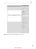
as shown in the figure.
Starting CATIA V5R16 using the taskbar shortcuts
CATIA V5R16 for Designers
Introduction
The initial screen that appears after starting CATIA V5R16
CATIA V5R16 for Designers
Introduction
The screen that appears after closing the initial product file
Introduction
CATIA V5R16 for Designers
¾ IMPORTANT TERMS AND DEFINITIONS
• Feature-based Modeling
• A feature is defined as the smallest building block that can be modified individually.
• A model created in CATIA V5 is a combination of a number of individual features and
each feature is related to the other directly or indirectly.
• Parametric Modeling
The parametric nature of a software package is defined as its ability to use the standard
properties or parameters in defining the shape and size of a geometry.
Body of a pipe housing
Modified body of pipe housing
CATIA V5R16 for Designers
Introduction
• Bidirectional Associativity
The bidirectional associativity ensures that if any modification is made in the model in any
one of the workbenches of CATIA V5, it is automatically reflected in the other workbenches
immediately.
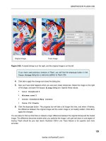
The drawing views of the body part
before making the modifications
The drawing views, after modifications
CATIA V5R16 for Designers
Introduction
• CATPart
CATPart is a file extension associated with all the files that are created in Sketcher, Part
Design, and Wireframe and Surface Design workbenches of CATIA V5.
• CATProduct
CATProduct is a file extension associated with all the files that are created in Assembly
Design workbench of CATIA V5.
• CATDrawing
CATDrawing is a file extension associated with all the files that are created in Drafting
workbench of CATIA V5.
CATIA V5R16 for Designers
Introduction
• Specification Tree
• The specification tree keeps a track of all the operations
that are carried on the part, as shown in the figure.
• The specification tree that appears when you start a new
file under the Part Design workbench, is as shown in the
figure.
The specification tree that
appears on starting a new
CATPart file
• Compass
• It is a tool that is used to manipulate the orientation of parts,
assemblies, or sketches.
• You can also orient the view of the parts and assemblies.
• By default, it appears on the top right corner of the geometry
area.
The Compass
CATIA V5R16 for Designers
Introduction
• Constraints
• Constraints are logical operations that are performed on the selected element to define its
size and location with respect to other elements or reference geometries.
• The constraints in Sketcher workbench are called geometric constraints and the constraints
available in the Assembly Design workbench are called assembly constraints.
• Geometric Constraints
These are the logical operations performed on sketched elements to define their size and
position with respect to other elements.
CATIA V5R16 for Designers
The constraints available in the Sketcher workbench are:
• Distance
• Fix
• Length
• Coincident
• Angle
• Concentricity
• Radius / Diameter
• Tangency
• Semimajor axis
• Parallelism
• Semiminor axis
• Perpendicular
• Symmetry
• Horizontal
• Midpoint
• Vertical
• Equidistant point
Introduction
Introduction
CATIA V5R16 for Designers
• Assembly Constraints
Constraints available in the Assembly Design workbench are logical operations performed
to restrict the degree of freedom of the component and to precisely define their location and
position with respect to other components of the assembly.
• Coincidence Constraint
• Fix Component
• Contact Constraint
• Fix Together
• Offset Constraint
• Quick Constraint
• Angle Constraint
• PartBody
• It is the default body available under Part Design workbench.
• All the solid related features, such as pad, pocket, shaft, and so on are placed inside it.
CATIA V5R16 for Designers
Introduction
• Geometrical Set
The geometrical set is defined as a body that includes newly created planes, surfaces,
wireframe elements, and reference elements.
• Wireframe
The wireframe construction elements aid in creating surfaces and are used as a substitute
to entities drawn in the Sketcher workbench.
• Surface
• Surface are geometric feature which have no thickness.
• They are generally used to create complex shapes that are difficult to create using the
solid feature.
• Feature
• A features is defined as a basic building block of a solid model.
• The combination of various features results in a complete model.
CATIA V5R16 for Designers
Introduction
• Reframe on
Sometimes a feature, body, or a sketch may not be visible in the available space in the
geometry area, this operation is used to view that particular selection in the available
display space.
• Center Graph
This option brings the selected feature, body, or sketch in the specification tree to the
middle left portion of the geometry area.
CATIA V5R16 for Designers
Introduction
¾ UNDERSTANDING THE FUNCTIONS OF THE MOUSE
BUTTONS
• To work with CATIA V5 design workbenches, it is necessary that you understand the
functions of the mouse buttons.
• The efficient usage of these three buttons, along with the CTRL key on the keyboard, can
reduce the time involved in completing the design task.
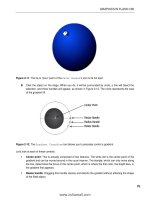
Using the three button mouse
to perform the zoom in and
zoom out operations
Using the three button mouse to
perform the rotate operation
CATIA V5R16 for Designers
Introduction
¾ TOOLBARS
• CATIA V5 offers a user-friendly design environment by providing specific toolbars to each
workbench.
• The toolbars that appear in various workbenches are:
• Standard Toolbar
• This toolbar is common to all workbenches of CATIA V5.
• The following figure shows the Standard toolbar.
The Standard toolbar
Introduction
CATIA V5R16 for Designers
• Status Bar
The Status bar, which appears at the bottom of the CATIA V5 window, comprises of three
areas, as shown in the figure.
The status Bar
• Current Information or Dialog Box
The Current Information or Dialog Box area displays the current information about the
selected feature or current tool.
• Power Input Field Bar
The Power Input Field bar lets you invoke the commands and enter the data or value that
can be directly associated with the feature.
CATIA V5R16 for Designers
Introduction
• Dialog Box Display Button
Choosing the Dialog Box Display button will turn on and turn off the display of the current
dialog box.
• User Information Package Button
Choosing this button will open a window with a default link that is C:\Program Files\Dassault
Systemes\B16\intel_a\resources\galaxy\default.htm.
• Part Design Workbench Toolbars
You can invoke the Part Design workbench by choosing the New button from the Standard
toolbar and selecting Part from the New dialog box.
CATIA V5R16 for Designers
• View Toolbar
The View toolbar
• Select Toolbar
The Select toolbar
• Sketcher Toolbar
The Sketcher toolbar
Introduction
CATIA V5R16 for Designers
• Profile Toolbar
The Profile toolbar
• Constraint Toolbar
The Constraint toolbar
• Operation Toolbar
The Operation toolbar
Introduction
CATIA V5R16 for Designers
• Sketch tools Toolbar
The Sketch tools toolbar
• Sketch-Based Features Toolbar
The Sketch-Based Features toolbar
• Dress-Up Features Toolbar
The Dress-Up Features toolbar
Introduction
CATIA V5R16 for Designers
• Measure Toolbar
The Measure toolbar
• Transformation Features Toolbar
The Transformation Features toolbar
• Surface-Based Features Toolbar
The Surface-Based Features toolbar
Introduction
CATIA V5R16 for Designers
Introduction
• Apply Material Toolbar
The Apply Material
toolbar
• Wireframe and Surface Design Workbench Toolbars
You can invoke the Wireframe and Surface Design workbench from the main menu bar
by choosing Start > Mechanical Design > Wireframe and Surface Design.
• Surfaces Toolbar
The Surfaces toolbar