Interpreting engineering drawings 8th edition (2015)
Bạn đang xem bản rút gọn của tài liệu. Xem và tải ngay bản đầy đủ của tài liệu tại đây (24.13 MB, 530 trang )
InterpretIng
engIneerIng
DrawIngs
EIGHTH EDITION
THEODOrE J. BraNOff
Illinois State University
Australia Brazil Japan Korea Mexico Singapore Spain United Kingdom United States
●
●
●
●
●
●
●
●
Copyright 2016 Cengage Learning. All Rights Reserved. May not be copied, scanned, or duplicated, in whole or in part. Due to electronic rights, some third party content may be suppressed from the eBook and/or eChapter(s).
Editorial review has deemed that any suppressed content does not materially affect the overall learning experience. Cengage Learning reserves the right to remove additional content at any time if subsequent rights restrictions require it.
This is an electronic version of the print textbook. Due to electronic rights restrictions, some third party content may be suppressed. Editorial
review has deemed that any suppressed content does not materially affect the overall learning experience. The publisher reserves the right to
remove content from this title at any time if subsequent rights restrictions require it. For valuable information on pricing, previous
editions, changes to current editions, and alternate formats, please visit www.cengage.com/highered to search by
ISBN#, author, title, or keyword for materials in your areas of interest.
Important Notice: Media content referenced within the product description or the product text may not be available in the eBook version.
Copyright 2016 Cengage Learning. All Rights Reserved. May not be copied, scanned, or duplicated, in whole or in part. Due to electronic rights, some third party content may be suppressed from the eBook and/or eChapter(s).
Editorial review has deemed that any suppressed content does not materially affect the overall learning experience. Cengage Learning reserves the right to remove additional content at any time if subsequent rights restrictions require it.
Interpreting Engineering Drawings,
Eighth Edition
Theodore J. Branoff
Senior Vice President, GM Skills & Global
Product Management: Dawn Gerrain
Product Manager: Daniel Johnson
Senior Director Development:
Marah Bellegarde
Senior Product Development Manager:
Larry Main
Content Developer: Richard Hall
Product Assistant: Andrew Ouimet
Senior Production Director: Wendy A. Troeger
Production Manager: Andrew Crouth
© 2016, 2007 Cengage Learning
WCN: 02-200-203
ALL RIGHTS RESERVED. No part of this work covered by the copyright herein
may be reproduced, transmitted, stored, or used in any form or by any means
graphic, electronic, or mechanical, including but not limited to photocopying,
recording, scanning, digitizing, taping, Web distribution, information networks,
or information storage and retrieval systems, except as permitted under
Section 107 or 108 of the 1976 United States Copyright Act, without the prior
written permission of the publisher.
For product information and technology assistance, contact us at
Cengage Learning Customer & Sales Support, 1-800-354-9706
For permission to use material from this text or product,
submit all requests online at www.cengage.com/permissions.
Further permissions questions can be e-mailed to
Senior Content Project Manager: Glenn Castle
Art Director: Bethany Casey
Library of Congress Control Number: 2014950539
Technology Project Manager: Joe Pliss
ISBN: 978-1-1336-9359-8
Production Service: Prashant Kumar Das,
MPS Limited
Compositor: MPS Limited
Cover image(s): © iStockphoto.com/adventtr
Cengage Learning
200 First Stamford Place, 4th Floor
Stamford, CT 06902
USA
Cengage Learning is a leading provider of customized learning solutions with
office locations around the globe, including Singapore, the United Kingdom,
Australia, Mexico, Brazil, and Japan. Locate your local office at:
www.cengage.com/global
Cengage Learning products are represented in Canada by Nelson Education, Ltd.
To learn more about Cengage Learning, visit www.cengage.com
Purchase any of our products at your local college store or at our preferred
online store www.cengagebrain.com
Notice to the Reader
Publisher does not warrant or guarantee any of the products described herein or perform any independent
analysis in connection with any of the product information contained herein. Publisher does not assume,
and expressly disclaims, any obligation to obtain and include information other than that provided to it by
the manufacturer. The reader is expressly warned to consider and adopt all safety precautions that might be
indicated by the activities described herein and to avoid all potential hazards. By following the instructions
contained herein, the reader willingly assumes all risks in connection with such instructions. The publisher
makes no representations or warranties of any kind, including but not limited to, the warranties of fitness for
particular purpose or merchantability, nor are any such representations implied with respect to the material set
forth herein, and the publisher takes no responsibility with respect to such material. The publisher shall not be
liable for any special, consequential, or exemplary damages resulting, in whole or part, from the readers’ use of,
or reliance upon, this material.
Printed in the United States of America
Print Number: 01 Print Year: 2014
Copyright 2016 Cengage Learning. All Rights Reserved. May not be copied, scanned, or duplicated, in whole or in part. Due to electronic rights, some third party content may be suppressed from the eBook and/or eChapter(s).
Editorial review has deemed that any suppressed content does not materially affect the overall learning experience. Cengage Learning reserves the right to remove additional content at any time if subsequent rights restrictions require it.
Contents
Preface � � � � � � � � � � � � � � � � � � � � � � � � � � � � � � � � � � � � � x
About the Author � � � � � � � � � � � � � � � � � � � � � � � � � � � � xiii
Acknowledgments � � � � � � � � � � � � � � � � � � � � � � � � � � � xiv
Working Drawings and Projection Theory � � � � � � � 22
11
11
12
12
12
Working Drawings � � � � � � � � � � � � � � � � � � � � � � � � � � � � 22
Arrangement of Views � � � � � � � � � � � � � � � � � � � � � � � � � 23
ISo Projection Symbol � � � � � � � � � � � � � � � � � � � � � � � � 24
Third-Angle Projection � � � � � � � � � � � � � � � � � � � � � � � � 24
First-Angle Projection � � � � � � � � � � � � � � � � � � � � � � � � � 27
View Layout � � � � � � � � � � � � � � � � � � � � � � � � � � � � � � � � 27
Sketching Views in Third-Angle Projection � � � � � � � � �29
Reference � � � � � � � � � � � � � � � � � � � � � � � � � � � � � � � � � � 31
Internet Resources � � � � � � � � � � � � � � � � � � � � � � � � � � � 31
Assignments
A-7 � � � � � � Matching Drawings—1 � � � � � � � � � � � 32
A-8 � � � � � � Matching Drawings—2 � � � � � � � � � � � � 33
A-9 � � � � � � orthographic Sketching Visible
and Hidden Lines � � � � � � � � � � � � � � � � 34
A-10 � � � � � orthographic Sketching of Parts
Having Circular Features � � � � � � � � � � 35
A-11 � � � � � orthographic Sketching of Parts
Having Flat Surfaces–Decimal-Inch
Dimensioning � � � � � � � � � � � � � � � � � � � 36
A-12M
orthographic Sketching of Parts
Having Flat Surfaces–Millimeter
Dimensioning � � � � � � � � � � � � � � � � � � � 37
A-13 � � � � � orthographic Sketching of Parts
Having Circular Features–DecimalInch Dimensioning � � � � � � � � � � � � � � � 38
13
14
Unit 5
Unit 1
Introduction: Line Types and Sketching � � � � � � � � � 1
Bases for Interpreting Drawings � � � � � � � � � � � � � � � � � � 1
Engineering Drawings � � � � � � � � � � � � � � � � � � � � � � � � � � 2
Lines Used to Describe the Shape of a Part � � � � � � � � 2
Sketching � � � � � � � � � � � � � � � � � � � � � � � � � � � � � � � � � � � � 6
Information Shown on Assignment Drawings � � � � � � � 9
References � � � � � � � � � � � � � � � � � � � � � � � � � � � � � � � � � � 9
Internet Resources � � � � � � � � � � � � � � � � � � � � � � � � � � � � 9
Assignments
A-1M
Sketching Lines, Circles, and Arcs � � � 10
A-2 � � � � � � Inlay Designs � � � � � � � � � � � � � � � � � � � � 10
Unit 2
Lettering and Title Blocks � � � � � � � � � � � � � � � � � � � � 11
Lettering � � � � � � � � � � � � � � � � � � � � � � � � � � � � � � � � � � � �
Title Blocks and Title Strips � � � � � � � � � � � � � � � � � � � �
Drawing to Scale � � � � � � � � � � � � � � � � � � � � � � � � � � � � �
Reference � � � � � � � � � � � � � � � � � � � � � � � � � � � � � � � � � �
Internet Resources � � � � � � � � � � � � � � � � � � � � � � � � � � �
Assignments
A-3 � � � � � � Garden Gate � � � � � � � � � � � � � � � � � � � �
A-4 � � � � � � Roof Truss � � � � � � � � � � � � � � � � � � � � � �
Unit 4
Introduction to Dimensioning � � � � � � � � � � � � � � � � 39
Unit 3
Basic Geometry: Circles and Arcs � � � � � � � � � � � � � � 15
Circular Features � � � � � � � � � � � � � � � � � � � � � � � � � � � � �
Sketching Circles and Arcs � � � � � � � � � � � � � � � � � � � � �
Reference � � � � � � � � � � � � � � � � � � � � � � � � � � � � � � � � � �
Internet Resources � � � � � � � � � � � � � � � � � � � � � � � � � � �
Assignments
A-5 � � � � � � Sketching Circles and Arcs—1 � � � � �
A-6M
Sketching Circles and Arcs—2 � � � � � �
15
15
19
19
20
21
Dimensioning � � � � � � � � � � � � � � � � � � � � � � � � � � � � � � � �
Reading Direction � � � � � � � � � � � � � � � � � � � � � � � � � � � �
Dimensioning Flat Surfaces � � � � � � � � � � � � � � � � � � � �
Reference Dimensions � � � � � � � � � � � � � � � � � � � � � � � �
Not-to-Scale Dimensions � � � � � � � � � � � � � � � � � � � � � �
References � � � � � � � � � � � � � � � � � � � � � � � � � � � � � � � � �
Internet Resources � � � � � � � � � � � � � � � � � � � � � � � � � � �
Assignments
A-14 � � � � � Feed Hopper � � � � � � � � � � � � � � � � � � �
A-15 � � � � � Coupling � � � � � � � � � � � � � � � � � � � � � � �
39
40
40
46
46
47
47
48
49
iii
Copyright 2016 Cengage Learning. All Rights Reserved. May not be copied, scanned, or duplicated, in whole or in part. Due to electronic rights, some third party content may be suppressed from the eBook and/or eChapter(s).
Editorial review has deemed that any suppressed content does not materially affect the overall learning experience. Cengage Learning reserves the right to remove additional content at any time if subsequent rights restrictions require it.
iv
Contents
A-16 � � � � � Third-Angle Projection and
Dimensioning � � � � � � � � � � � � � � � � � � � 50
A-17M
Third-Angle Projection and
Dimensioning � � � � � � � � � � � � � � � � � � � 51
Unit 6
Normal, Inclined, and Oblique Surfaces � � � � � � � � � 52
Normal Surfaces � � � � � � � � � � � � � � � � � � � � � � � � � � � � � 52
Inclined Surfaces � � � � � � � � � � � � � � � � � � � � � � � � � � � � � 53
oblique Surfaces � � � � � � � � � � � � � � � � � � � � � � � � � � � � � 53
Measurement of Angles � � � � � � � � � � � � � � � � � � � � � � � 55
Symmetrical outlines � � � � � � � � � � � � � � � � � � � � � � � � � 56
Machine Slots � � � � � � � � � � � � � � � � � � � � � � � � � � � � � � � � 56
References � � � � � � � � � � � � � � � � � � � � � � � � � � � � � � � � � 58
Assignments
A-18 � � � � � Base Plate � � � � � � � � � � � � � � � � � � � � � � 59
A-19 � � � � � Compound Rest Slide � � � � � � � � � 60–61
A-20 � � � � � orthographic Sketching of
objects Having Sloped Surfaces
Using Grid Lines � � � � � � � � � � � � � � � � � 62
A-21 � � � � � orthographic Sketching of Parts
Having Sloped Surfaces Using
Decimal-Inch Dimensioning � � � � � � � 63
A-22M
orthographic Sketching of Parts
Having Sloped Surfaces Using
Millimeter Dimensioning � � � � � � � � � � 64
A-23 � � � � � Identifying oblique Surfaces � � � � � � � 65
A-24 � � � � � Completing oblique Surfaces � � � � � � 66
Unit 7
Pictorial Sketching � � � � � � � � � � � � � � � � � � � � � � � � � 67
Introduction � � � � � � � � � � � � � � � � � � � � � � � � � � � � � � � � �
Isometric Sketching � � � � � � � � � � � � � � � � � � � � � � � � � � �
oblique Sketching � � � � � � � � � � � � � � � � � � � � � � � � � � � �
Reference � � � � � � � � � � � � � � � � � � � � � � � � � � � � � � � � � �
Internet Resources � � � � � � � � � � � � � � � � � � � � � � � � � � �
Assignments
A-25 � � � � � Pictorial Sketching of Parts Having
Flat Surfaces Using Decimal-Inch
Dimensioning � � � � � � � � � � � � � � � � � � �
A-26M
Pictorial Sketching of Parts Having
Flat Surfaces Using Millimeter
Dimensioning � � � � � � � � � � � � � � � � � � �
A-27 � � � � � Pictorial Sketching of Parts Having
Circular Features Using Decimal-Inch
Dimensioning � � � � � � � � � � � � � � � � � � �
A-28M
Pictorial Sketching of Parts Having
Circular Features Using Metric
Dimensioning � � � � � � � � � � � � � � � � � � �
67
68
69
73
73
74
75
Unit 8
Machining Symbols and Revision Blocks � � � � � � � � 78
Machining Symbols � � � � � � � � � � � � � � � � � � � � � � � � � � � 78
Drawing Revisions � � � � � � � � � � � � � � � � � � � � � � � � � � � � 80
References � � � � � � � � � � � � � � � � � � � � � � � � � � � � � � � � � 80
Internet Resources � � � � � � � � � � � � � � � � � � � � � � � � � � � 81
Assignments
A-29M
offset Bracket � � � � � � � � � � � � � � � 82–83
A-30 � � � � � Guide Bar �� � � � � � � � � � � � � � � � � � � 84–85
Unit 9
Chamfers, Undercuts, Tapers, and Knurls � � � � � � � 86
Chamfers � � � � � � � � � � � � � � � � � � � � � � � � � � � � � � � � � � �
Undercuts � � � � � � � � � � � � � � � � � � � � � � � � � � � � � � � � � � �
Tapers � � � � � � � � � � � � � � � � � � � � � � � � � � � � � � � � � � � � � �
Knurls � � � � � � � � � � � � � � � � � � � � � � � � � � � � � � � � � � � � � �
Reference � � � � � � � � � � � � � � � � � � � � � � � � � � � � � � � � � �
Internet Resources � � � � � � � � � � � � � � � � � � � � � � � � � � �
Assignments
A-31 � � � � � Handle � � � � � � � � � � � � � � � � � � � � � � � �
A-32M
Indicator Rod � � � � � � � � � � � � � � � � � � � �
86
87
87
87
88
88
89
90
Unit 10
Sectional Views � � � � � � � � � � � � � � � � � � � � � � � � � � � � 91
Introduction � � � � � � � � � � � � � � � � � � � � � � � � � � � � � � � � � 91
Types of Sections � � � � � � � � � � � � � � � � � � � � � � � � � � � � � 93
Revolved and Removed Sections � � � � � � � � � � � � � � � � 95
Broken-out and Partial Sections � � � � � � � � � � � � � � � � 97
Countersinks, Counterbores, and Spotfaces � � � � � � 98
Intersection of Unfinished Surfaces � � � � � � � � � � � � � � 98
References � � � � � � � � � � � � � � � � � � � � � � � � � � � � � � � � � 99
Internet Resources � � � � � � � � � � � � � � � � � � � � � � � � � � � 99
Assignments
A-33 � � � � � Sketching Full Sections � � � � � � � � � � 101
A-34 � � � � � Slide Bracket � � � � � � � � � � � � � � � 102–103
A-35M
Base Plate � � � � � � � � � � � � � � � � � 104–105
A-36 � � � � � Sketching Half Sections � � � � � � � � � � 106
A-37 � � � � � Shaft Intermediate Support � � � � � � � 107
A-38 � � � � � Shaft Supports �� � � � � � � � � � � � � 108–109
Unit 11
One-and Two-View Drawings � � � � � � � � � � � � � � � � 110
76
77
Introduction � � � � � � � � � � � � � � � � � � � � � � � � � � � � � � � � 110
Multiple-Detail Drawings � � � � � � � � � � � � � � � � � � � � � 110
Functional Drafting � � � � � � � � � � � � � � � � � � � � � � � � � � 111
Copyright 2016 Cengage Learning. All Rights Reserved. May not be copied, scanned, or duplicated, in whole or in part. Due to electronic rights, some third party content may be suppressed from the eBook and/or eChapter(s).
Editorial review has deemed that any suppressed content does not materially affect the overall learning experience. Cengage Learning reserves the right to remove additional content at any time if subsequent rights restrictions require it.
v
Contents
Reference � � � � � � � � � � � � � � � � � � � � � � � � � � � � � � � � � 113
Internet Resources � � � � � � � � � � � � � � � � � � � � � � � � � � 113
Assignments
A-39 � � � � � Centering Connector Details � � � 114–115
A-40M
Link � � � � � � � � � � � � � � � � � � � � � � � � � � � 116
Assignments
A-46 � � � � � Inch Fits–Basic Hole System � � � � � � 148
A-47 � � � � � Inch Fits � � � � � � � � � � � � � � � � � � � � � � � 149
Unit 15
Metric Fits � � � � � � � � � � � � � � � � � � � � � � � � � � � � � � � 150
Unit 12
Surface Texture � � � � � � � � � � � � � � � � � � � � � � � � � � � 117
Introduction � � � � � � � � � � � � � � � � � � � � � � � � � � � � � � � � 117
Surface Texture Symbol� � � � � � � � � � � � � � � � � � � � � � � 119
Surface Texture Ratings � � � � � � � � � � � � � � � � � � � � � � � 119
Control Requirements � � � � � � � � � � � � � � � � � � � � � � � � 122
Reference � � � � � � � � � � � � � � � � � � � � � � � � � � � � � � � � � 123
Internet Resources � � � � � � � � � � � � � � � � � � � � � � � � � � 123
Assignments
A-41M
Caster Details � � � � � � � � � � � � � � 126–127
A-42 � � � � � Hanger Details � � � � � � � � � � � � � 128–129
Introduction � � � � � � � � � � � � � � � � � � � � � � � � � � � � � � � � 150
References � � � � � � � � � � � � � � � � � � � � � � � � � � � � � � � � 154
Internet Resource � � � � � � � � � � � � � � � � � � � � � � � � � � � 154
Assignments
A-48M
Metric Fits–Basic Hole System � � � � 156
A-49M
Metric Fits � � � � � � � � � � � � � � � � � � � � � 157
A-50M
Bracket � � � � � � � � � � � � � � � � � � � � 158–159
A-51M
Swivel � � � � � � � � � � � � � � � � � � � � � � � � � 160
Unit 16
Threads and Fasteners � � � � � � � � � � � � � � � � � � � � � 161
Unit 13
Introduction to Conventional Tolerancing � � � � � � 130
Tolerances and Allowances� � � � � � � � � � � � � � � � � � � � 130
Definitions � � � � � � � � � � � � � � � � � � � � � � � � � � � � � � � � � 130
Tolerancing Methods � � � � � � � � � � � � � � � � � � � � � � � � 131
Dimension origin Symbol� � � � � � � � � � � � � � � � � � � � � 133
Rectangular Coordinate Dimensioning
Without Dimension Lines � � � � � � � � � � � � � � � � � � � � � 134
Rectangular Coordinate Dimensioning
in Tabular Form � � � � � � � � � � � � � � � � � � � � � � � � � � � � � � 134
Chain Dimensioning � � � � � � � � � � � � � � � � � � � � � � � � � 134
Base Line (Datum) Dimensioning � � � � � � � � � � � � � � � 134
Reference � � � � � � � � � � � � � � � � � � � � � � � � � � � � � � � � � 135
Internet Resources � � � � � � � � � � � � � � � � � � � � � � � � � � 135
Assignments
A-43 � � � � � Inch Tolerances and Allowances � � � 138
A-44M
Millimeter Tolerances and
Allowances � � � � � � � � � � � � � � � � � � � � 139
A-45 � � � � � Support Bracket � � � � � � � � � � � � 140–141
Unit 17
Unit 14
Auxiliary Views � � � � � � � � � � � � � � � � � � � � � � � � � � � 181
Inch Fits � � � � � � � � � � � � � � � � � � � � � � � � � � � � � � � � � 142
Introduction � � � � � � � � � � � � � � � � � � � � � � � � � � � � � � � �
Description of Fits � � � � � � � � � � � � � � � � � � � � � � � � � � �
Standard Inch Fits � � � � � � � � � � � � � � � � � � � � � � � � � � �
References � � � � � � � � � � � � � � � � � � � � � � � � � � � � � � � �
Internet Resources � � � � � � � � � � � � � � � � � � � � � � � � � �
Threaded Fasteners� � � � � � � � � � � � � � � � � � � � � � � � � � 161
Threaded Assemblies � � � � � � � � � � � � � � � � � � � � � � � � 162
Threaded Holes � � � � � � � � � � � � � � � � � � � � � � � � � � � � � 164
Inch Threads � � � � � � � � � � � � � � � � � � � � � � � � � � � � � � � � 164
Right- and Left-Handed Threads � � � � � � � � � � � � � � � 165
Metric Threads � � � � � � � � � � � � � � � � � � � � � � � � � � � � � � 165
Keys� � � � � � � � � � � � � � � � � � � � � � � � � � � � � � � � � � � � � � � 168
Set Screws � � � � � � � � � � � � � � � � � � � � � � � � � � � � � � � � � 169
Flats� � � � � � � � � � � � � � � � � � � � � � � � � � � � � � � � � � � � � � � 170
Bosses and Pads � � � � � � � � � � � � � � � � � � � � � � � � � � � � 171
References � � � � � � � � � � � � � � � � � � � � � � � � � � � � � � � � 171
Internet Resources � � � � � � � � � � � � � � � � � � � � � � � � � � 171
Assignments
A-52M
Drive Support Details � � � � � � � 172–173
A-53 � � � � � Housing Details � � � � � � � � � � � � � 174–175
A-54M
V-Block Assembly � � � � � � � � � � � � � � � 176
A-55 � � � � � Terminal Block � � � � � � � � � � � � � � � � � � 177
A-57 � � � � � Rack Details � � � � � � � � � � � � � � � � 178–179
A-56M
Terminal Stud � � � � � � � � � � � � � � � � � � 180
142
142
145
147
147
Primary Auxiliary Views � � � � � � � � � � � � � � � � � � � � � � �
Secondary Auxiliary Views � � � � � � � � � � � � � � � � � � � �
Reference � � � � � � � � � � � � � � � � � � � � � � � � � � � � � � � � �
Internet Resources � � � � � � � � � � � � � � � � � � � � � � � � � �
Assignments
A-58 � � � � � Gear Box � � � � � � � � � � � � � � � � � � � � � �
A-59 � � � � � Inclined Stop � � � � � � � � � � � � � � � � � � �
Copyright 2016 Cengage Learning. All Rights Reserved. May not be copied, scanned, or duplicated, in whole or in part. Due to electronic rights, some third party content may be suppressed from the eBook and/or eChapter(s).
Editorial review has deemed that any suppressed content does not materially affect the overall learning experience. Cengage Learning reserves the right to remove additional content at any time if subsequent rights restrictions require it.
181
183
183
183
184
185
vi
Contents
A-60 � � � � � Hexagon Bar Support � � � � � � � � 186–187
A-61 � � � � � Control Block �� � � � � � � � � � � � � � 188–189
Unit 18
Development Drawings � � � � � � � � � � � � � � � � � � � � 190
Introduction � � � � � � � � � � � � � � � � � � � � � � � � � � � � � � � �
Joints, Seams, and Edges � � � � � � � � � � � � � � � � � � � � �
Sheet Metal Sizes � � � � � � � � � � � � � � � � � � � � � � � � � � �
Straight Line Development � � � � � � � � � � � � � � � � � � � �
Radial Line Development � � � � � � � � � � � � � � � � � � � � �
Stampings � � � � � � � � � � � � � � � � � � � � � � � � � � � � � � � � �
Reference � � � � � � � � � � � � � � � � � � � � � � � � � � � � � � � � �
Internet Resources � � � � � � � � � � � � � � � � � � � � � � � � � �
Assignments
A-62 � � � � � Letter Box � � � � � � � � � � � � � � � � � � � � �
A-63M
Bracket � � � � � � � � � � � � � � � � � � � � � � � �
190
190
190
190
191
191
194
194
195
195
Unit 19
Selection and Arrangement of Views � � � � � � � � � � 196
Arrangement of Views � � � � � � � � � � � � � � � � � � � � � � � � 196
Necessary Views � � � � � � � � � � � � � � � � � � � � � � � � � � � � 198
Reference � � � � � � � � � � � � � � � � � � � � � � � � � � � � � � � � � 198
Internet Resource � � � � � � � � � � � � � � � � � � � � � � � � � � � 198
Assignments
A-64 � � � � � Mounting Plate � � � � � � � � � � � � � � � � � 199
A-65 � � � � � Index Pedestal �� � � � � � � � � � � � � 200–201
Unit 20
Piping Drawings � � � � � � � � � � � � � � � � � � � � � � � � � � 202
Piping � � � � � � � � � � � � � � � � � � � � � � � � � � � � � � � � � � � � � 202
Piping Drawings � � � � � � � � � � � � � � � � � � � � � � � � � � � � � 205
Pipe Drawing Symbols � � � � � � � � � � � � � � � � � � � � � � � 205
References � � � � � � � � � � � � � � � � � � � � � � � � � � � � � � � � 208
Internet Resources � � � � � � � � � � � � � � � � � � � � � � � � � � 208
Assignments
A-66 � � � � � Engine Starting Air System � � � 210–211
A-67 � � � � � Boiler Room � � � � � � � � � � � � � � � � 212–213
Unit 21
Bearings � � � � � � � � � � � � � � � � � � � � � � � � � � � � � � � � 214
Introduction � � � � � � � � � � � � � � � � � � � � � � � � � � � � � � � �
Plain Bearings � � � � � � � � � � � � � � � � � � � � � � � � � � � � � �
Premounted Bearings � � � � � � � � � � � � � � � � � � � � � � � �
References � � � � � � � � � � � � � � � � � � � � � � � � � � � � � � � �
214
214
216
216
Internet Resources � � � � � � � � � � � � � � � � � � � � � � � � � � 216
Assignments
A-68M
Adjustable Shaft Support � � � � � � � � 217
A-69 � � � � � Corner Bracket � � � � � � � � � � � � � 218–219
Unit 22
Manufacturing Materials � � � � � � � � � � � � � � � � � � � � 220
Introduction � � � � � � � � � � � � � � � � � � � � � � � � � � � � � � � � 220
Cast Irons � � � � � � � � � � � � � � � � � � � � � � � � � � � � � � � � � � 220
Steel � � � � � � � � � � � � � � � � � � � � � � � � � � � � � � � � � � � � � � 221
Plastics � � � � � � � � � � � � � � � � � � � � � � � � � � � � � � � � � � � � 222
Rubber � � � � � � � � � � � � � � � � � � � � � � � � � � � � � � � � � � � � 225
Internet Resources � � � � � � � � � � � � � � � � � � � � � � � � � � 225
Assignments
A-70M
Crossbar � � � � � � � � � � � � � � � � � � � � � � 227
A-71 � � � � � oil Chute � � � � � � � � � � � � � � � � � � 228–229
A-72M
Parallel Clamp Details � � � � � � � � � � � 230
A-73M
Caster Assembly � � � � � � � � � � � � � � � � 231
Unit 23
Casting Processes � � � � � � � � � � � � � � � � � � � � � � � � � 232
Introduction � � � � � � � � � � � � � � � � � � � � � � � � � � � � � � � � 232
Casting Design � � � � � � � � � � � � � � � � � � � � � � � � � � � � � 234
Cored Castings � � � � � � � � � � � � � � � � � � � � � � � � � � � � � 237
Machining Lugs � � � � � � � � � � � � � � � � � � � � � � � � � � � � � 237
Surface Coatings � � � � � � � � � � � � � � � � � � � � � � � � � � � � 238
Reference � � � � � � � � � � � � � � � � � � � � � � � � � � � � � � � � � 238
Internet Resources � � � � � � � � � � � � � � � � � � � � � � � � � � 238
Assignments
A-74 � � � � � offset Bracket � � � � � � � � � � � � � � � � � 239
A-75 � � � � � Trip Box � � � � � � � � � � � � � � � � � � � 240–241
A-76 � � � � � Auxiliary Pump Base � � � � � � � � � 242–243
A-78 � � � � � Interlock Base � � � � � � � � � � � � � � 244–245
A-77M
Slide Valve � � � � � � � � � � � � � � � � � � � � � 246
A-79M
Contact Arm � � � � � � � � � � � � � � � � � � � 247
A-80M
Contactor � � � � � � � � � � � � � � � � � � � � � � 248
Unit 24
Violating True Projection: Conventional Practices
249
Alignment of Parts and Holes � � � � � � � � � � � � � � � � � �
Partial Views � � � � � � � � � � � � � � � � � � � � � � � � � � � � � � � �
Naming of Views for Spark Adjuster � � � � � � � � � � � �
Drill Sizes � � � � � � � � � � � � � � � � � � � � � � � � � � � � � � � � � �
Webs in Section � � � � � � � � � � � � � � � � � � � � � � � � � � � � �
Ribs in Section � � � � � � � � � � � � � � � � � � � � � � � � � � � � � �
Spokes in Section � � � � � � � � � � � � � � � � � � � � � � � � � � �
249
250
251
251
252
252
254
Copyright 2016 Cengage Learning. All Rights Reserved. May not be copied, scanned, or duplicated, in whole or in part. Due to electronic rights, some third party content may be suppressed from the eBook and/or eChapter(s).
Editorial review has deemed that any suppressed content does not materially affect the overall learning experience. Cengage Learning reserves the right to remove additional content at any time if subsequent rights restrictions require it.
vii
Contents
Reference � � � � � � � � � � � � � � � � � � � � � � � � � � � � � � � � � 254
Internet Resources � � � � � � � � � � � � � � � � � � � � � � � � � � 254
Assignments
A-81 � � � � � Spark Adjuster � � � � � � � � � � � � � 256–257
A-82 � � � � � Control Bracket � � � � � � � � � � � � � 258–259
A-83M
Raise Block � � � � � � � � � � � � � � � � 260–261
A-84M
Coil Frame � � � � � � � � � � � � � � � � � 262–263
Conical Washers � � � � � � � � � � � � � � � � � � � � � � � � � � � � 291
Reference � � � � � � � � � � � � � � � � � � � � � � � � � � � � � � � � � 291
Internet Resources � � � � � � � � � � � � � � � � � � � � � � � � � � 291
Assignment
A-91 � � � � � Four-Wheel Trolley � � � � � � � � � � 292–293
Unit 29
Welding Drawings � � � � � � � � � � � � � � � � � � � � � � � � � 294
Unit 25
Pin Fasteners � � � � � � � � � � � � � � � � � � � � � � � � � � � � � 264
Introduction � � � � � � � � � � � � � � � � � � � � � � � � � � � � � � � � 264
Section Through Shafts, Pins, and Keys � � � � � � � � � � � 268
Arrangement of Views of Drawing A-85M � � � � � � � � 268
References � � � � � � � � � � � � � � � � � � � � � � � � � � � � � � � � 269
Internet Resources � � � � � � � � � � � � � � � � � � � � � � � � � � 269
Assignments
A-85M
Spider � � � � � � � � � � � � � � � � � � � � 270–271
A-86 � � � � � Hood � � � � � � � � � � � � � � � � � � � � � 272–273
Introduction � � � � � � � � � � � � � � � � � � � � � � � � � � � � � � � �
Welding Symbols � � � � � � � � � � � � � � � � � � � � � � � � � � � �
Fillet Welds� � � � � � � � � � � � � � � � � � � � � � � � � � � � � � � � �
Reference � � � � � � � � � � � � � � � � � � � � � � � � � � � � � � � � �
Internet Resources � � � � � � � � � � � � � � � � � � � � � � � � � �
Assignments
A-92 � � � � � Fillet Welds � � � � � � � � � � � � � � � � � � � �
A-93 � � � � � Shaft Support � � � � � � � � � � � � � � � � � �
294
294
298
301
301
303
304
Unit 30
Groove Welds � � � � � � � � � � � � � � � � � � � � � � � � � � � � 305
Unit 26
Drawings for Numerical Control � � � � � � � � � � � � � � 274
Introduction � � � � � � � � � � � � � � � � � � � � � � � � � � � � � � � �
Dimensioning for Numerical Control � � � � � � � � � � � �
Dimensioning for Two-Axis Coordinate System
Internet Resources � � � � � � � � � � � � � � � � � � � � � � � � � �
Assignments
A-87 � � � � � Cover Plate � � � � � � � � � � � � � � � � � � � �
A-88M
Terminal Board � � � � � � � � � � � � � � � � �
274
274
275
276
Types of Groove Welds � � � � � � � � � � � � � � � � � � � � � � � 305
Supplementary Symbols � � � � � � � � � � � � � � � � � � � � � � 307
Reference � � � � � � � � � � � � � � � � � � � � � � � � � � � � � � � � � 309
Internet Resource � � � � � � � � � � � � � � � � � � � � � � � � � � � 309
Assignments
A-94 � � � � � Base Skid � � � � � � � � � � � � � � � � � 312–313
A-95 � � � � � Groove Welds � � � � � � � � � � � � � � � � � � 314
278
279
Unit 31
Unit 27
Assembly Drawings� � � � � � � � � � � � � � � � � � � � � � � � 280
Introduction � � � � � � � � � � � � � � � � � � � � � � � � � � � � � � � � 280
Bill of Material (Parts or Items List) � � � � � � � � � � � � � � 282
Helical Springs � � � � � � � � � � � � � � � � � � � � � � � � � � � � � � 282
References � � � � � � � � � � � � � � � � � � � � � � � � � � � � � � � � 285
Internet Resources � � � � � � � � � � � � � � � � � � � � � � � � � � 285
Assignments
A-89 � � � � � Fluid Pressure Valve � � � � � � � � � 286–287
A-90M
Parallel Clamp Assembly � � � � � � � � � 288
Other Basic Welds� � � � � � � � � � � � � � � � � � � � � � � � � 315
Plug and Slot Welds � � � � � � � � � � � � � � � � � � � � � � � � � 315
Reference � � � � � � � � � � � � � � � � � � � � � � � � � � � � � � � � � 323
Internet Resources � � � � � � � � � � � � � � � � � � � � � � � � � � 323
Assignments
A-96
Base Assembly � � � � � � � � � � � � � 324–325
A-97 � � � � � Plug, Slot, and Spot Welds � � � � � � � 326
A-98 � � � � � Seam and flange Welds � � � � � � � � � � 327
Unit 32
Spur Gears � � � � � � � � � � � � � � � � � � � � � � � � � � � � � � 328
Unit 28
Structural Steel � � � � � � � � � � � � � � � � � � � � � � � � � � � 289
Structural Steel Shapes � � � � � � � � � � � � � � � � � � � � � � � 289
Phantom outlines � � � � � � � � � � � � � � � � � � � � � � � � � � � 291
Introduction � � � � � � � � � � � � � � � � � � � � � � � � � � � � � � � �
Spur Gears � � � � � � � � � � � � � � � � � � � � � � � � � � � � � � � � �
Reference � � � � � � � � � � � � � � � � � � � � � � � � � � � � � � � � �
Internet Resources � � � � � � � � � � � � � � � � � � � � � � � � � �
Copyright 2016 Cengage Learning. All Rights Reserved. May not be copied, scanned, or duplicated, in whole or in part. Due to electronic rights, some third party content may be suppressed from the eBook and/or eChapter(s).
Editorial review has deemed that any suppressed content does not materially affect the overall learning experience. Cengage Learning reserves the right to remove additional content at any time if subsequent rights restrictions require it.
328
329
333
333
viii
Contents
Assignments
A-99 � � � � � Spur Gear � � � � � � � � � � � � � � � � � 334–335
A-100 � � � � Spur Gear Calculations �� � � � � � � � � � 336
Unit 33
Bevel Gears and Gear Trains� � � � � � � � � � � � � � � � � 337
Bevel Gears � � � � � � � � � � � � � � � � � � � � � � � � � � � � � � � � 337
Gear Trains � � � � � � � � � � � � � � � � � � � � � � � � � � � � � � � � � 338
Reference � � � � � � � � � � � � � � � � � � � � � � � � � � � � � � � � � 341
Internet Resources � � � � � � � � � � � � � � � � � � � � � � � � � � 341
Assignments
A-101 � � � � Miter Gear � � � � � � � � � � � � � � � � 342–343
A-102 � � � � Motor Drive Assembly � � � � � � � 344–345
A-103 � � � � Gear Train Calculations � � � � � � � � � � 346
Unit 34
Cams � � � � � � � � � � � � � � � � � � � � � � � � � � � � � � � � � � � 347
Introduction � � � � � � � � � � � � � � � � � � � � � � � � � � � � � � � � 347
Internet Resources � � � � � � � � � � � � � � � � � � � � � � � � � � 349
Assignments
A-104 � � � � Cylindrical Feeder Cam � � � � � � 350–351
A-105 � � � � Plate Cam � � � � � � � � � � � � � � � � � � � � � 352
Unit 35
Bearings and Clutches � � � � � � � � � � � � � � � � � � � � � 353
Antifriction Bearings � � � � � � � � � � � � � � � � � � � � � � � � � 353
Retaining Rings � � � � � � � � � � � � � � � � � � � � � � � � � � � � � 355
o-Ring Seals� � � � � � � � � � � � � � � � � � � � � � � � � � � � � � � � 355
Clutches � � � � � � � � � � � � � � � � � � � � � � � � � � � � � � � � � � � 355
Belt Drives � � � � � � � � � � � � � � � � � � � � � � � � � � � � � � � � � 355
References � � � � � � � � � � � � � � � � � � � � � � � � � � � � � � � � 358
Internet Resources � � � � � � � � � � � � � � � � � � � � � � � � � � 359
Assignment
A-106 � � � � Power Drive � � � � � � � � � � � � � � � 360–361
Unit 36
Ratchet Wheels � � � � � � � � � � � � � � � � � � � � � � � � � � � 362
Introduction � � � � � � � � � � � � � � � � � � � � � � � � � � � � � � � � 362
Internet Resource � � � � � � � � � � � � � � � � � � � � � � � � � � � 365
Assignment
A-107 � � � � Winch � � � � � � � � � � � � � � � � � � � � 366–367
Unit 37
Introduction to Geometric Dimensioning
and Tolerancing � � � � � � � � � � � � � � � � � � � � � � � � � � � 368
Modern Engineering Tolerancing � � � � � � � � � � � � � � 368
Geometric Tolerancing � � � � � � � � � � � � � � � � � � � � � � � 370
Feature Control Frame � � � � � � � � � � � � � � � � � � � � � � � 371
Form Tolerances � � � � � � � � � � � � � � � � � � � � � � � � � � � � 372
Straightness � � � � � � � � � � � � � � � � � � � � � � � � � � � � � � � � 373
Straightness Controlling Surface Elements � � � � � � � 374
Reference � � � � � � � � � � � � � � � � � � � � � � � � � � � � � � � � � 377
Internet Resources � � � � � � � � � � � � � � � � � � � � � � � � � � 377
Assignment
A-108 � � � � Straightness Tolerance Controlling
Surface Elements � � � � � � � � � � � 378–379
Unit 38
Features and Material Condition Modifiers � � � � � 380
Features With and Without Size � � � � � � � � � � � � � � � � 380
Material Condition Definitions � � � � � � � � � � � � � � � � � 380
Material Condition Symbols � � � � � � � � � � � � � � � � � � � 383
Examples � � � � � � � � � � � � � � � � � � � � � � � � � � � � � � � � � � 384
Maximum Material Condition (MMC) � � � � � � � � � � � 385
Regardless of Feature Size (RFS) � � � � � � � � � � � � � � � 386
Least Material Condition (LMC) � � � � � � � � � � � � � � � � 386
Straightness of a Feature of Size � � � � � � � � � � � � � � � 386
Reference � � � � � � � � � � � � � � � � � � � � � � � � � � � � � � � � � 391
Internet Resources � � � � � � � � � � � � � � � � � � � � � � � � � � 391
Assignment
A-109 � � � � Straightness of a Feature
of Size � � � � � � � � � � � � � � � � � � � � 392–393
Unit 39
Form Tolerances � � � � � � � � � � � � � � � � � � � � � � � � � � 394
Introduction � � � � � � � � � � � � � � � � � � � � � � � � � � � � � � � � 394
Flatness� � � � � � � � � � � � � � � � � � � � � � � � � � � � � � � � � � � � 394
Circularity � � � � � � � � � � � � � � � � � � � � � � � � � � � � � � � � � � 396
Cylindricity � � � � � � � � � � � � � � � � � � � � � � � � � � � � � � � � � 397
Reference � � � � � � � � � � � � � � � � � � � � � � � � � � � � � � � � � 399
Internet Resources � � � � � � � � � � � � � � � � � � � � � � � � � � 399
Assignment
A-110 � � � � Form Tolerances � � � � � � � � � � � � 400–401
Unit 40
The Datum Reference Frame � � � � � � � � � � � � � � � � 402
Datums and the Three-Plane Concept � � � � � � � � � � 402
Copyright 2016 Cengage Learning. All Rights Reserved. May not be copied, scanned, or duplicated, in whole or in part. Due to electronic rights, some third party content may be suppressed from the eBook and/or eChapter(s).
Editorial review has deemed that any suppressed content does not materially affect the overall learning experience. Cengage Learning reserves the right to remove additional content at any time if subsequent rights restrictions require it.
ix
Contents
Datums for Geometric Tolerancing � � � � � � � � � � � � � 402
Three-Plane System � � � � � � � � � � � � � � � � � � � � � � � � � � 403
Uneven Surfaces � � � � � � � � � � � � � � � � � � � � � � � � � � � � 406
Datum Feature Symbol � � � � � � � � � � � � � � � � � � � � � � � 406
Reference � � � � � � � � � � � � � � � � � � � � � � � � � � � � � � � � � 409
Internet Resources � � � � � � � � � � � � � � � � � � � � � � � � � � 409
Assignments
A-111 � � � � Datums � � � � � � � � � � � � � � � � � � � 412–413
A-112M
Axle � � � � � � � � � � � � � � � � � � � � � � � � � � 414
Unit 41
Orientation Tolerances � � � � � � � � � � � � � � � � � � � � � 415
Introduction � � � � � � � � � � � � � � � � � � � � � � � � � � � � � � � �
orientation Tolerancing for Flat Surfaces � � � � � � � �
orientation Tolerancing for Features of Size� � � � � � � �
Internal Cylindrical Features � � � � � � � � � � � � � � � � � � �
External Cylindrical Features � � � � � � � � � � � � � � � � � �
Reference � � � � � � � � � � � � � � � � � � � � � � � � � � � � � � � � �
Internet Resources � � � � � � � � � � � � � � � � � � � � � � � � � �
Assignments
A-113 � � � � Stand � � � � � � � � � � � � � � � � � � � � � � � � �
A-114M
Cut-off Stand � � � � � � � � � � � � � � � � � �
A-115 � � � � orientation Tolerancing
for Features of Size � � � � � � � � � � � � � �
415
417
417
422
427
427
427
429
430
431
Unit 42
Datum Targets � � � � � � � � � � � � � � � � � � � � � � � � � � � � 432
Introduction � � � � � � � � � � � � � � � � � � � � � � � � � � � � � � � �
Datum-Target Symbol � � � � � � � � � � � � � � � � � � � � � � � �
Reference � � � � � � � � � � � � � � � � � � � � � � � � � � � � � � � � �
Internet Resources � � � � � � � � � � � � � � � � � � � � � � � � � �
Assignment
A-116
Bearing Housing � � � � � � � � � � � � � � �
432
432
437
437
439
Unit 43
Position Tolerances � � � � � � � � � � � � � � � � � � � � � � � � 440
Tolerancing of Features by Position � � � � � � � � � � � � �
Tolerancing Methods � � � � � � � � � � � � � � � � � � � � � � � �
Coordinate Tolerancing � � � � � � � � � � � � � � � � � � � � � �
Advantages of Coordinate Tolerancing � � � � � � � � � �
Disadvantages of Coordinate Tolerancing � � � � � � �
Positional Tolerancing � � � � � � � � � � � � � � � � � � � � � � � �
440
440
441
444
444
444
Material Condition Basis � � � � � � � � � � � � � � � � � � � � � � 445
Positional Tolerancing for Circular Features � � � � � � 445
Advantages of Positional Tolerancing � � � � � � � � � � � 450
Selection of Datum Features for Positional
Tolerancing � � � � � � � � � � � � � � � � � � � � � � � � � � � � � � � � � 453
Long Holes � � � � � � � � � � � � � � � � � � � � � � � � � � � � � � � � � 454
Circular Datums � � � � � � � � � � � � � � � � � � � � � � � � � � � � � 454
Multiple Holes as a Datum � � � � � � � � � � � � � � � � � � � � 456
Reference � � � � � � � � � � � � � � � � � � � � � � � � � � � � � � � � � 457
Internet Resources � � � � � � � � � � � � � � � � � � � � � � � � � � 457
Assignments
A-117 � � � � Positional Tolerancing � � � � � � � 458–459
A-118 � � � � Datum Selection for Positional
Tolerancing � � � � � � � � � � � � � � � � � � � � 460
Unit 44
Profile Tolerances � � � � � � � � � � � � � � � � � � � � � � � � � 461
Introduction � � � � � � � � � � � � � � � � � � � � � � � � � � � � � � � �
Profile of a Line � � � � � � � � � � � � � � � � � � � � � � � � � � � � �
Profile of a Surface � � � � � � � � � � � � � � � � � � � � � � � � � � �
Profile Zone Boundaries � � � � � � � � � � � � � � � � � � � � � �
Reference � � � � � � � � � � � � � � � � � � � � � � � � � � � � � � � � �
Internet Resources � � � � � � � � � � � � � � � � � � � � � � � � � �
Assignment
A-119 � � � � Profile Tolerancing � � � � � � � � � � � � � �
461
461
462
463
467
467
468
Unit 45
Runout Tolerances � � � � � � � � � � � � � � � � � � � � � � � � � 469
Introduction � � � � � � � � � � � � � � � � � � � � � � � � � � � � � � � � 469
Circular Runout � � � � � � � � � � � � � � � � � � � � � � � � � � � � � 470
Total Runout � � � � � � � � � � � � � � � � � � � � � � � � � � � � � � � � 471
Establishing Datums � � � � � � � � � � � � � � � � � � � � � � � � � 471
Reference � � � � � � � � � � � � � � � � � � � � � � � � � � � � � � � � � 474
Internet Resources � � � � � � � � � � � � � � � � � � � � � � � � � � 474
Assignments
A-120 � � � � Runout Tolerances � � � � � � � � � � 476–477
A-121 � � � � Housing � � � � � � � � � � � � � � � � � � � 478–479
A-122M
End Plate � � � � � � � � � � � � � � � � � � � � � � 480
Appendix
������������������������
481
index � � � � � � � � � � � � � � � � � � � � � � � � � � � � � � 509
Copyright 2016 Cengage Learning. All Rights Reserved. May not be copied, scanned, or duplicated, in whole or in part. Due to electronic rights, some third party content may be suppressed from the eBook and/or eChapter(s).
Editorial review has deemed that any suppressed content does not materially affect the overall learning experience. Cengage Learning reserves the right to remove additional content at any time if subsequent rights restrictions require it.
PrefACe
The eighth edition of Interpreting Engineering Drawings is the most comprehensive and up-to-date text of its kind. The text has been revised to best prepare students to enter twenty-first-century technology-intensive industries.
It is also useful to those individuals working in technology-based industries
who feel the need to enhance their understanding of key aspects of twentyfirst-century technology. To that end, the text offers the flexibility needed
to provide instruction in as narrow or as broad a customized program of
studies as is required or desired. Clearly, it provides the theory and practical application for individuals to develop the intellectual skills needed
to communicate technical concepts used throughout the international
marketplace.
Flexibility is the key to developing a program of studies designed to meet
the needs of every student. Interpreting Engineering Drawings, eighth edition, is
designed to allow instructors and students to pick and choose specific units of
instruction based on individual needs and interests.
Although students should cover everything offered in the core material in the
text (Units 1 through 17), advanced topics are offered throughout the remaining
28 units to provide opportunities for students to become highly skilled in understanding only selected advanced subjects or a broad range of subjects that spread
over nearly all aspects of modern industry. Additionally, ancillary materials offered on the Instructor Companion Website, as well as the Internet Resources
listed at the end of each unit, provide for a more in-depth understanding of the
material covered. Through the use of these ancillary materials, the depth of understanding achieved is limited only by the student’s time constraints and the
desire to master the material provided.
It is important to know that the entire text is developed around the most
current standards accepted throughout industry. This includes both decimalinch and metric (millimeter) sizes and related concepts. Both systems are
introduced early in the text and are reinforced in both theory and practical
application through the broad range of assignments at the end of each unit.
These concepts are further reinforced as students are encouraged to use the
Appendix at the end of the text. Tables in the Appendix are given in both
systems of measure.
Features that made Interpreting Engineering Drawings highly successful
in previous editions continue to be used in the eighth edition. For example, as
always, the text carefully examines the very basic concepts needed to understand
technical drawings and meticulously and methodically takes the student through
x
Copyright 2016 Cengage Learning. All Rights Reserved. May not be copied, scanned, or duplicated, in whole or in part. Due to electronic rights, some third party content may be suppressed from the eBook and/or eChapter(s).
Editorial review has deemed that any suppressed content does not materially affect the overall learning experience. Cengage Learning reserves the right to remove additional content at any time if subsequent rights restrictions require it.
Preface
progressively more complex issues. Plenty of carefully developed illustrations,
reinforced by the use of a second color, provide a clear understanding of material covered in the written text. Assignments provided at the end of each unit are
designed to measure the student’s understanding of the material covered as well
as reinforce the theoretical concepts.
Further, only after the student develops a clear understanding of basic concepts is he or she introduced to more advanced units such as modern engineering tolerancing (geometric dimensioning and tolerancing), manufacturing
materials and processes, welding drawings, piping, and other similar advanced
topics.
Although Interpreting Engineering Drawings has always used sketching
practices as a means of reinforcing the student’s understanding of technical
information, the eighth edition greatly expands this important technique. Not
only does sketching enhance the student’s understanding of technical concepts, it also enhances his or her ability to communicate technical concepts
more effectively.
In keeping with the dynamic changes in the field of engineering graphics,
various new features have been added to this eighth edition.
feAtUres of the eighth edition
●●
●●
●●
New and revised figures. Figures have been added and revised to clarify national and international standards including line types, first-angle projection,
developments, selection and arrangement of views and to clarify the applications of geometric dimensioning and tolerancing.
Standards update. All drawings in the text have been updated to conform to the
latest ASME drawing standards.
Internet resources. Internet sources have been revised and search terms
have been added to help students find useful additional resources on unit
material.
The authors and the publisher hope you find the eighth edition of Interpreting Engineering Drawings to be as practical and useful as you have the previous
editions.
Please feel free to contact us through the publisher if you have questions or comments about the book.
sUPPLeMents
The Instructor Companion Website to Accompany Interpreting Engineering
Drawings offers free resources for instructors to enhance the educational experience. The Website contains unit presentations in PowerPoint™, Grid Sheets,
Assignments List, Lesson Plans, Assignment Solutions, Test Assignments and
Solutions, and an Image Gallery.
Copyright 2016 Cengage Learning. All Rights Reserved. May not be copied, scanned, or duplicated, in whole or in part. Due to electronic rights, some third party content may be suppressed from the eBook and/or eChapter(s).
Editorial review has deemed that any suppressed content does not materially affect the overall learning experience. Cengage Learning reserves the right to remove additional content at any time if subsequent rights restrictions require it.
xi
xii
Preface
Accessing an instructor Companion Website from
sso front door
1� Go to and log in, using the instructor e-mail address and password.
2� Enter author, title, or ISBN in the Add a title to your bookshelf search.
3� Click Add to my bookshelf to add instructor resources.
4� At the Product page, click the Instructor Companion site link.
Cengage Learning testing (CLt)
Powered by Cognero CLT is a flexible, online system that allows you to
●●
●●
●●
Author, edit, and manage test bank content from multiple Cengage Learning
solutions.
Create multiple test versions in an instant.
Deliver tests from your LMS, your classroom, or wherever you want.
Contact Cengage Learning or your local sales representative to obtain an instructor account.
Copyright 2016 Cengage Learning. All Rights Reserved. May not be copied, scanned, or duplicated, in whole or in part. Due to electronic rights, some third party content may be suppressed from the eBook and/or eChapter(s).
Editorial review has deemed that any suppressed content does not materially affect the overall learning experience. Cengage Learning reserves the right to remove additional content at any time if subsequent rights restrictions require it.
ABoUt the AUthor
theodore J. Branoff, Ph.d. is currently a member of the Engineering
Design Graphics Division of the American Society for Engineering Education;
the Association of Technology, Management, and Applied Engineering; the
International Society for Geometry and Graphics; the International Technology
and Engineering Educators Association; the Associate for Career and Technical
Education; and Epsilon Pi Tau. He served as president of ISGG from 2009 to 2012.
In 2013 he was elected into the Academy of Fellows of the American Society for
Engineering Education, and in 2014 he received the Distinguished Service Award
from the Engineering Design Graphics Division of ASEE.
xiii
Copyright 2016 Cengage Learning. All Rights Reserved. May not be copied, scanned, or duplicated, in whole or in part. Due to electronic rights, some third party content may be suppressed from the eBook and/or eChapter(s).
Editorial review has deemed that any suppressed content does not materially affect the overall learning experience. Cengage Learning reserves the right to remove additional content at any time if subsequent rights restrictions require it.
ACKnoWLedgMents
The author would like to thank and acknowledge the many professionals who
reviewed the manuscript.
A special acknowledgment is due to the following instructors, who reviewed
the chapters in detail:
Lora Eddington, Wake Technical Community College, Raleigh, North
Carolina
Robert A. Chin, East Carolina University, Greenville, North Carolina
Ed Espin, Burlington, Ontario, Canada
xiv
Copyright 2016 Cengage Learning. All Rights Reserved. May not be copied, scanned, or duplicated, in whole or in part. Due to electronic rights, some third party content may be suppressed from the eBook and/or eChapter(s).
Editorial review has deemed that any suppressed content does not materially affect the overall learning experience. Cengage Learning reserves the right to remove additional content at any time if subsequent rights restrictions require it.
Unit 1
INTRODUCTION: LINE TYPES AND SKETCHING
BASES FOR intERPREtinG
DRAWinGS
Commonly Used
Descriptive terms
When looking at objects, we normally see them as
three-dimensional—as having width, depth, and
height; or length, width, and height. The choice of
terms used depends on the shape and proportions
of the object.
Spherical shapes, such as a basketball,
would be described as having a certain diameter
(one term).
Cylindrical shapes, such as a baseball bat,
would have diameter and length. A hockey puck
would have diameter and thickness (two terms).
Objects that are not spherical or cylindrical
require three terms to describe their overall shape.
The terms used for a car would probably be length,
width, and height; for a filing cabinet—width,
height, and depth, even though the longest measurement (length) could be the width, height, or
depth; for a sheet of drawing paper—length, width,
and thickness. The terms used are interchangeable
according to the proportions of the object being
described, and the position it is in when being
viewed. For example, a telephone pole lying on the
ground would be described as having diameter and
length, but when placed in a vertical position, its
dimensions would be diameter and height.
In order to avoid confusion, distances from
left to right are referred to as width, distances
from front to back as depth, and vertical distances
(except when very small in proportion to the
others) as height.
the need for Standardization
Engineering drawings are more complicated and
require a set of rules, terms, and symbols that
everyone can understand and use. A drawing
showing a part may be drawn in New York, the part
made in California, and then sent to Michigan for
assembly. If this is to be successfully accomplished,
the drawing must have only one interpretation.
Most countries set up standards committees
to accomplish this feat. These committees must
decide on factors such as the best methods of
representation, dimensioning and tolerancing, and
the adopting of drawing symbols. Different styles
of lines must be established to represent visible or
hidden lines, or to indicate the center of a feature.
If only one interpretation of a drawing is to be met,
then the rules must be followed and interpreted
correctly.
In the United States, drawing standards are
established by the American Society of Mechanical
Engineers (ASME) and in Canada, by the Canadian
Standards Association (CSA). Members of these
committees are part of the worldwide committee
on standardization, known as the International
Organization for Standardization (ISO).
1
Copyright 2016 Cengage Learning. All Rights Reserved. May not be copied, scanned, or duplicated, in whole or in part. Due to electronic rights, some third party content may be suppressed from the eBook and/or eChapter(s).
Editorial review has deemed that any suppressed content does not materially affect the overall learning experience. Cengage Learning reserves the right to remove additional content at any time if subsequent rights restrictions require it.
2
Interpreting Engineering Drawings
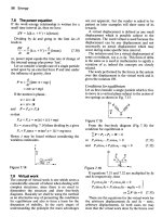
FiGURE 1–1 Pictorial sketches.
7
6
5
4
3
2
1
7
(A) ISOMETRIC SKETCH
(B) OBLIQUE SKETCH
The drawings and information shown throughout this text are based on the ASME-Y14 Series
of Drawing Standard Practices. In some areas of
drawing practice, such as in simplified drafting, national standards have not yet been established. The authors have, in such cases, adopted
the practices used by leading industries in the
United States.
Engineering or technical drawings furnish a
description of the shape and size of an object. Other
information necessary for the construction of the
object is given in a way that renders it readily recognizable to anyone familiar with engineering drawings.
Pictorial drawings are similar to photographs,
because they show objects as they would appear to
the eye of the observer, Figure 1–1. Such drawings,
however, are not often used for technical designs
because interior features and complicated details
are easier to understand and dimension on orthographic drawings. The drawings used in industry
must clearly show the exact shape of objects. This
usually cannot be accomplished in just one pictorial view because many details of the object may
be hidden or not clearly shown when the object is
viewed from only one side.
For this reason, the drafter must show a
number of views of the object as seen from different directions. These views, referred to as front
view, top view, right-side view, and so forth, are
systematically arranged on the drawing sheet
and projected from one another, Figure 1–2.
6
5
4
3
2
1
0
1
2
3
67
4 5
(C) PERSPECTIVE SKETCH
This type of projection is called orthographic
projection and is explained in Unit 4. The ability to understand and visualize an object from
these views is essential in the interpretation of
engineering drawings.
EnGinEERinG DRAWinGS
Throughout the history of engineering drawings,
many drawing conventions, terms, abbreviations,
and practices have come into common use. It is
essential that all drafters, designers, and engineers
use the same practices if drafting and sketching
are to serve as a reliable means of communicating
technical theory and applications.
An engineering drawing consists of a variety
of line styles, symbols, and lettering. When positioned correctly on the drawing paper, they convey
precise information to the reader.
LinES USED tO DESCRiBE
tHE SHAPE OF A PARt
Line Styles
Most objects drawn in engineering offices are
complicated and contain many surfaces and edges.
For this reason, a line is the fundamental, and
Copyright 2016 Cengage Learning. All Rights Reserved. May not be copied, scanned, or duplicated, in whole or in part. Due to electronic rights, some third party content may be suppressed from the eBook and/or eChapter(s).
Editorial review has deemed that any suppressed content does not materially affect the overall learning experience. Cengage Learning reserves the right to remove additional content at any time if subsequent rights restrictions require it.
3
Unit 1
FiGURE 1–2 Systematic arrangement of views.
TOP VIEW
FRONT VIEW
perhaps the most important, single entity on an
engineering drawing. Lines are used to illustrate
and describe the shape and size of objects that will
later become real parts. The various lines used on
engineering drawings form the alphabet of the
drafting language. Like letters of the alphabet, they
are different in their appearance. Some are light—
others are dark. Some are thick—others are thin.
Some are solid—others are dashed in various ways.
Figure 1–3 illustrates the various types of lines used
in engineering drawing. These will be explained in
more detail throughout the units of this textbook.
Construction Lines
When first laying out a sketch, light, thin, solid
lines are used to develop the shape and location of
features. These lines are called construction lines,
RIGHT-SIDE VIEW
and being very thin and light, are normally left on
the sketch.
Visible Lines
Visible lines are thick, continuous, bold lines used
to indicate all visible edges of an object. They
should stand out clearly in contrast to other lines,
so that the shape of an object is quickly apparent
to the eye.
Hidden Lines
Hidden lines are used to describe features that cannot be seen. They are positioned on the view in the
same manner as visible lines. These lines consist of
short, evenly spaced thin dashes and spaces. The
dashes are three to four times as long as the spaces.
Copyright 2016 Cengage Learning. All Rights Reserved. May not be copied, scanned, or duplicated, in whole or in part. Due to electronic rights, some third party content may be suppressed from the eBook and/or eChapter(s).
Editorial review has deemed that any suppressed content does not materially affect the overall learning experience. Cengage Learning reserves the right to remove additional content at any time if subsequent rights restrictions require it.
4
Interpreting Engineering Drawings
FiGURE 1–3 Alphabet of lines.
Thick (0.6mm or .024”)
VISIBLE LINE
Thin (0.3mm or .012”)
HIDDEN LINE
Thin
CENTER LINE
Thick
SYMMETRY LINE
Thick
FREEHAND BREAK LINE
Thin
LONG BREAK LINE
Leader (Thin)
DIMENSION LINE
EXTENSION LINE
LEADER
Dimension Line (Thin)
4.000
Extension Line (Thin)
Section Line (Thin)
SECTION LINE
Thick
CUTTING-PLANE LINE
or
VIEWING-PLANE LINE
Thick
Thick
PHANTOM LINE or
REFERENCE LINE
Thin
Thin
STITCH LINE
CHAIN LINE
These lines should begin and end with a dash in
contact with the line in which they start and end,
except when such a dash would form a continuation of a visible line. Dashes should join at corners.
Thin
Thick
Figure 1–4 shows examples of hidden line applications. Exceptions for these standards are permitted
when the views of a part are automatically generated by a CAD system.
Copyright 2016 Cengage Learning. All Rights Reserved. May not be copied, scanned, or duplicated, in whole or in part. Due to electronic rights, some third party content may be suppressed from the eBook and/or eChapter(s).
Editorial review has deemed that any suppressed content does not materially affect the overall learning experience. Cengage Learning reserves the right to remove additional content at any time if subsequent rights restrictions require it.
5
Unit 1
(extended) for use as extension lines for dimensioning purposes. In this case, the extended portion is
not broken, as shown in Figure 1–5, Example 1.
FiGURE 1–4 Hidden lines.
1
2
3
Break Lines
Break lines serve many purposes. For example, they
are used to shorten the view of long uniform sections,
which saves valuable drawing space, Figure 1–6(A).
6
4
5
(A) GATE
(B) ROD SUPPORT
FiGURE 1–6 The use of break lines.
46
1
2
3
4
5
6
Center Lines
Due to tooling and manufacturing requirements,
circular, cylindrical, and symmetrical parts, including holes, must have their centers located. A special line, referred to as a center line, is used to locate
these features. A center line is drawn as a thin,
broken line of long and short dashes, spaced alternately, as shown in Figure 1–5. The long and short
dashes may vary in length, depending on the size
of the drawing. Center lines may be used to indicate center points, axes (singular, axis) of cylindrical parts, and axes of symmetrically shaped surfaces
or parts. Solid center lines are often used on small
holes (Figure 1–5, Example 1), but the broken line is
preferred (Example 2). Center lines should project
for a short distance beyond the outline of the part or
feature to which they refer. They may be lengthened
THICK WAVY BREAK LINES
(A) TO SHORTEN LENGTH
THICK WAVY BREAK LINES
(B) NOT SHOWING UNNECESSARY DETAILS
FiGURE 1–5 Center line application.
FOR SMALL HOLES USE SHORT
UNBROKEN CENTER LINES
USE TWO SHORT DASHES AT THE
POINT OF INTERSECTION
CENTER LINE SHOULD NOT BE BROKEN
WHEN IT ENDS BEYOND THE OBJECT LINE
EXAMPLE 2
EXAMPLE 1
Copyright 2016 Cengage Learning. All Rights Reserved. May not be copied, scanned, or duplicated, in whole or in part. Due to electronic rights, some third party content may be suppressed from the eBook and/or eChapter(s).
Editorial review has deemed that any suppressed content does not materially affect the overall learning experience. Cengage Learning reserves the right to remove additional content at any time if subsequent rights restrictions require it.
6
Interpreting Engineering Drawings
They are also used to remove a segment of a part that
serves no useful purpose on the drawing, thus saving
valuable drawing or sketching time, Figure 1–6(B). The
break line shown in this figure is one of several break
line styles used on engineering drawings. This particular type of break line is shown as a thick, solid line
because it forms part of the outline of the object being
drawn. It is the third line style used to show the outline of a part.
Another type of break line, as shown in
Figure 1–7, is used to shorten the view of long uniform sections. These types of break lines are also
used when only a partial view is required. Such lines
are used on both detail and assembly drawings. The
thin line with freehand zigzags is recommended for
long breaks, and the jagged line for wood parts. The
special breaks shown for cylindrical and tubular
parts are useful when an end view is not shown;
otherwise, the thick break line is adequate.
FiGURE 1–7 Conventional break lines.
Symbols and Abbreviations
THIN LINE
(A) LONG BREAK – ALL SHAPES
DRAWN FREEHAND
OR WITH TEMPLATE
Line and Space Lengths
There are several things to consider when
determining the lengths of lines and spaces for
center lines, hidden lines, and other lines with
dashes. The size and scale of the drawing will
influence the lengths and spaces needed. On larger
drawings (e.g., 34" 3 44") it might be more appropriate to have slightly longer lines and dashes than
on 8.5" × 11" drawings. It is important to maintain
the proportions such as the 3:1 ratio for hidden
lines. Some CAD programs will allow you to control this through a line type scaling command.
Symbols and abbreviations are extensively used on
engineering drawings. They reduce drawing time
and save valuable drawing space. The symbols are
truly a universal language, as their meanings are
understood in all countries. The first abbreviations
and symbols that you will see on the drawings in
this text are:
IN., meaning inch
mm, meaning millimeter
FT, meaning foot
Ø, meaning diameter
R, me aning radius
SKEtCHinG
SOLID CYLINDER
HOLLOW CYLINDER
USEFUL WHEN END VIEW IS NOT SHOWN
(B) CYLINDERS
Sketching is the simplest form of drawing. It is one
of the quickest ways to express ideas. The drafter,
technician, or engineer may use sketches to help
simplify and explain (communicate) thoughts and
concepts to other people. Sketching, therefore, is an
important and effective method of communication.
Sketching is also a part of drafting and design
because the drafter frequently sketches ideas and
designs prior to making the final drawing using
Copyright 2016 Cengage Learning. All Rights Reserved. May not be copied, scanned, or duplicated, in whole or in part. Due to electronic rights, some third party content may be suppressed from the eBook and/or eChapter(s).
Editorial review has deemed that any suppressed content does not materially affect the overall learning experience. Cengage Learning reserves the right to remove additional content at any time if subsequent rights restrictions require it.
7
Unit 1
computer-aided drafting (CAD). Sketching is also
used by designers and engineers during the ideation
and brainstorming processes. Practice in sketching helps develop a good sense of proportion and
accuracy of observation. It is also effective in resolving problems in the early stages of the design process.
CAD has replaced board drafting because of
its speed, versatility, and economy. Sketching, like
drafting, is also changing, and cost-saving methods
are being used to produce a sketch. For example,
grid-type sketching paper is used to reduce sketching time and to produce a neater and more accurate
sketch. This is because grid-type sketching paper
has a built-in ruler for measuring distance and
lines act as a straightedge when lines are drawn.
Not all of the drawing needs to be drawn freehand, if faster methods can be used. For example,
long lines can be drawn faster and more accurately
when a straightedge is used. Large circles and arcs
may be drawn or positioned by using a compass.
Small circles and arcs may be drawn with the aid
of a circle template.
FiGURE 1–8 Two-dimensional sketching paper.
Ø10.5
MATERIAL – 2 mm MYLAR
(A) ONE-VIEW SKETCH ON DECIMAL-INCH
(.01 INCH DIVISIONS) SKETCHING PAPER
Materials for Sketching
Sketching has two main advantages over formal
drawing. First, only a few materials and instruments are required to produce a sketch. Second,
you can produce a sketch anywhere. If many
sketches are to be made, such as when working
from this text, the sketching materials described
next should be considered.
SKETCHING PAPER
This type of paper has light, thin lines, and the
sketch is made directly on the paper. Various grid
sizes (spacings) and formats are available to suit
most drawing requirements. The two basic types
of sketching paper are two-dimensional and threedimensional sketching paper.
Two-Dimensional Sketching Paper. This type
of sketching paper is primarily used for drawing
one-view sketches and orthographic views, which
are covered in this unit and in Unit 4. The paper
has uniformly spaced horizontal and vertical
(B) ORTHOGRAPHIC SKETCH ON .25 INCH
DIVISION SKETCHING PAPER
lines that form squares. These are available in a
variety of grid sizes, Figure 1–8. The most commonly used spaces or grids are the decimal-inch,
fractional-inch, and centimeter. These spaces are
further subdivided into smaller spaces, such as
eighths or tenths of one inch or 1 mm. Because the
units of measure are not shown on these sheets,
the spaces can represent any desired unit of length.
Three-Dimensional Sketching Paper. Threedimensional sketching paper is designed for sketching pictorial drawings. There are three basic types:
isometric, oblique, and perspective, Figure 1–9.
Isometric sketching paper has evenly spaced
lines running in three directions. Isometric sketching is covered in Unit 7.
Copyright 2016 Cengage Learning. All Rights Reserved. May not be copied, scanned, or duplicated, in whole or in part. Due to electronic rights, some third party content may be suppressed from the eBook and/or eChapter(s).
Editorial review has deemed that any suppressed content does not materially affect the overall learning experience. Cengage Learning reserves the right to remove additional content at any time if subsequent rights restrictions require it.
8
Interpreting Engineering Drawings
PENCILS AND ERASERS
FiGURE 1–9 Three-dimensional sketching paper.
Soft lead pencils (grades F, H, or HB), properly
sharpened, are the best for sketching. Erasers that
are good for soft leads, such as a plastic eraser or a
kneaded-rubber eraser, are most commonly used.
TRIGONOMETRY SET
(A) ISOMETRIC SKETCHING
PAPER
(B) OBLIQUE SKETCHING
PAPER
This small, compact math set includes a compass,
plastic ruler, and triangles. These drawing tools are
very useful for sketching.
TEMPLATES
Oblique sketching paper is similar to twodimensional sketching paper except that 45° lines
that pass through the intersecting horizontal and
vertical lines are added in one or both directions.
Oblique sketching is covered in Unit 7.
One-, two-, and three-point perspective sketching papers are designed with worm’s- and bird’seye views. The spaces on the receding axes are
proportionately shortened to create a perspective
illusion. The sketches made on this type of paper
provide a more realistic view than the sketches
made on the isometric and oblique sketching
papers.
A circle template will improve the quality of your
sketches by making circles and arcs neat and uniform. It will also reduce sketching time. Elliptical
circle templates, which are used for pictorial
sketching, are normally made available in the
drafting classroom for use by students.
Sketching techniques
With reference to Figure 1–10, the following
sketching techniques were used:
●●
A 1-inch grid subdivided into tenths was
selected for the part to be sketched. It required
FiGURE 1–10 Sketch of a cover plate.
8.80
7.80
5.20
.50
2.60
.50
3.90
2.40
2.40
3.60
4.80
2.40
7.20
8.20
1.90
12X Ø.30
4.00
2X Ø.50
2X Ø1.10
MATERIAL – .12 STEEL PLATE
Copyright 2016 Cengage Learning. All Rights Reserved. May not be copied, scanned, or duplicated, in whole or in part. Due to electronic rights, some third party content may be suppressed from the eBook and/or eChapter(s).
Editorial review has deemed that any suppressed content does not materially affect the overall learning experience. Cengage Learning reserves the right to remove additional content at any time if subsequent rights restrictions require it.
9
Unit 1
●●
●●
decimal-inch dimensioning. The part was
sketched to half scale (half size). This type of
sketching paper simplified the measuring of
sizes and spacing and ensured accuracy when
parallel and vertical lines were drawn. The grid
lines also acted as guidelines for the lettering of notes and helped produce neat, legible
lettering.
A straightedge was used for drawing long lines.
This method of drawing lines was faster and more
accurate than if the lines were drawn freehand.
A circle template was used for drawing the
circular holes. Freehand sketching of round
holes is time-consuming and is not accurate or
pleasing to the eye.
inFORMAtiOn SHOWn On
shown after the assignment number located at
the bottom right-hand corner of the assignment
sheet. Circled numbers and letters shown in color
are used only to identify lines, distances, and
surfaces so that questions may be asked about
these features, as shown on Assignment A-14.
For purposes of clarity, the actual working drawing is shown in black. The information shown
in color is for instructional purposes only and
would not appear on working drawings found in
industry.
REFEREnCES
ASME Y14.2-2008 Line Conventions and Lettering
ASME Y14.38-2007 Abbreviations and Acronyms
ASSiGnMEnt DRAWinGS
intERnEt RESOURCES
Assignment problems are either in inch units of
measurement or in millimeters (metric). Metric
assignments are distinguishable by the letter M
Wikipedia, the Free Encyclopedia. For information
on engineering drawings and various line types, see:
/>
Copyright 2016 Cengage Learning. All Rights Reserved. May not be copied, scanned, or duplicated, in whole or in part. Due to electronic rights, some third party content may be suppressed from the eBook and/or eChapter(s).
Editorial review has deemed that any suppressed content does not materially affect the overall learning experience. Cengage Learning reserves the right to remove additional content at any time if subsequent rights restrictions require it.