FIBER REINFORCED COMPOSITES materials manufacturing and design
Bạn đang xem bản rút gọn của tài liệu. Xem và tải ngay bản đầy đủ của tài liệu tại đây (16.44 MB, 616 trang )
THIRD EDITION
FIBERREINFORCED
COMPOSITES
Materials, Manufacturing,
and Design
ß 2007 by Taylor & Francis Group, LLC.
ß 2007 by Taylor & Francis Group, LLC.
THIRD EDITION
FIBERREINFORCED
COMPOSITES
Materials, Manufacturing,
and Design
P.K.
Mallick
Department of Mechanical Engineering
University of Michigan-Dearborn
Dearborn, Michigan
Boca Raton London New York
CRC Press is an imprint of the
Taylor & Francis Group, an informa business
ß 2007 by Taylor & Francis Group, LLC.
CRC Press
Taylor & Francis Group
6000 Broken Sound Parkway NW, Suite 300
Boca Raton, FL 33487-2742
© 2008 by Taylor & Francis Group, LLC
CRC Press is an imprint of Taylor & Francis Group, an Informa business
No claim to original U.S. Government works
Printed in the United States of America on acid-free paper
10 9 8 7 6 5 4 3 2 1
International Standard Book Number-13: 978-0-8493-4205-9 (Hardcover)
This book contains information obtained from authentic and highly regarded sources. Reprinted material
is quoted with permission, and sources are indicated. A wide variety of references are listed. Reasonable
efforts have been made to publish reliable data and information, but the author and the publisher cannot
assume responsibility for the validity of all materials or for the consequences of their use.
No part of this book may be reprinted, reproduced, transmitted, or utilized in any form by any electronic,
mechanical, or other means, now known or hereafter invented, including photocopying, microfilming,
and recording, or in any information storage or retrieval system, without written permission from the
publishers.
For permission to photocopy or use material electronically from this work, please access www.copyright.
com ( or contact the Copyright Clearance Center, Inc. (CCC) 222 Rosewood
Drive, Danvers, MA 01923, 978-750-8400. CCC is a not-for-profit organization that provides licenses and
registration for a variety of users. For organizations that have been granted a photocopy license by the
CCC, a separate system of payment has been arranged.
Trademark Notice: Product or corporate names may be trademarks or registered trademarks, and are
used only for identification and explanation without intent to infringe.
Library of Congress Cataloging-in-Publication Data
Mallick, P.K., 1946Fiber-reinforced composites : materials, manufacturing, and design / P.K. Mallick.
-- 3rd ed.
p. cm.
Includes bibliographical references and index.
ISBN-13: 978-0-8493-4205-9 (alk. paper)
ISBN-10: 0-8493-4205-8 (alk. paper)
1. Fibrous composites. I. Title.
TA418.9.C6M28 2007
620.1’18--dc22
Visit the Taylor & Francis Web site at
and the CRC Press Web site at
ß 2007 by Taylor & Francis Group, LLC.
2007019619
To
my parents
ß 2007 by Taylor & Francis Group, LLC.
ß 2007 by Taylor & Francis Group, LLC.
Contents
Preface to the Third Edition
Author
Chapter 1
Introduction
1.1
1.2
1.3
Definition
General Characteristics
Applications
1.3.1 Aircraft and Military Applications
1.3.2 Space Applications
1.3.3 Automotive Applications
1.3.4 Sporting Goods Applications
1.3.5 Marine Applications
1.3.6 Infrastructure
1.4 Material Selection Process
References
Problems
Chapter 2
2.1
2.2
Materials
Fibers
2.1.1 Glass Fibers
2.1.2 Carbon Fibers
2.1.3 Aramid Fibers
2.1.4 Extended Chain Polyethylene Fibers
2.1.5 Natural Fibers
2.1.6 Boron Fibers
2.1.7 Ceramic Fibers
Matrix
2.2.1 Polymer Matrix
2.2.1.1 Thermoplastic and Thermoset Polymers
2.2.1.2 Unique Characteristics of Polymeric Solids
2.2.1.3 Creep and Stress Relaxation
2.2.1.4 Heat Deflection Temperature
2.2.1.5 Selection of Matrix: Thermosets
vs. Thermoplastics
ß 2007 by Taylor & Francis Group, LLC.
2.2.2 Metal Matrix
2.2.3 Ceramic Matrix
2.3 Thermoset Matrix
2.3.1 Epoxy
2.3.2 Polyester
2.3.3 Vinyl Ester
2.3.4 Bismaleimides and Other Thermoset Polyimides
2.3.5 Cyanate Ester
2.4 Thermoplastic Matrix
2.4.1 Polyether Ether Ketone
2.4.2 Polyphenylene Sulfide
2.4.3 Polysulfone
2.4.4 Thermoplastic Polyimides
2.5 Fiber Surface Treatments
2.5.1 Glass Fibers
2.5.2 Carbon Fibers
2.5.3 Kevlar Fibers
2.6 Fillers and Other Additives
2.7 Incorporation of Fibers into Matrix
2.7.1 Prepregs
2.7.2 Sheet-Molding Compounds
2.7.3 Incorporation of Fibers into Thermoplastic Resins
2.8 Fiber Content, Density, and Void Content
2.9 Fiber Architecture
References
Problems
Chapter 3
3.1
3.2
Mechanics
Fiber–Matrix Interactions in a Unidirectional Lamina
3.1.1 Longitudinal Tensile Loading
3.1.1.1 Unidirectional Continuous Fibers
3.1.1.2 Unidirectional Discontinuous Fibers
3.1.1.3 Microfailure Modes in Longitudinal Tension
3.1.2 Transverse Tensile Loading
3.1.3 Longitudinal Compressive Loading
3.1.4 Transverse Compressive Loading
Characteristics of a Fiber-Reinforced Lamina
3.2.1 Fundamentals
3.2.1.1 Coordinate Axes
3.2.1.2 Notations
3.2.1.3 Stress and Strain Transformations in a Thin
Lamina under Plane Stress
3.2.1.4 Isotropic, Anisotropic, and Orthotropic Materials
ß 2007 by Taylor & Francis Group, LLC.
3.2.2
Elastic Properties of a Lamina
3.2.2.1 Unidirectional Continuous Fiber 08 Lamina
3.2.2.2 Unidirectional Continuous Fiber
Angle-Ply Lamina
3.2.2.3 Unidirectional Discontinuous Fiber 08 Lamina
3.2.2.4 Randomly Oriented Discontinuous Fiber Lamina
3.2.3 Coefficients of Linear Thermal Expansion
3.2.4 Stress–Strain Relationships for a Thin Lamina
3.2.4.1 Isotropic Lamina
3.2.4.2 Orthotropic Lamina
3.2.5 Compliance and Stiffness Matrices
3.2.5.1 Isotropic Lamina
3.2.5.2 Specially Orthotropic Lamina (u ¼ 08 or 908)
3.2.5.3 General Orthotropic Lamina (u 6¼ 08 or 908)
3.3 Laminated Structure
3.3.1 From Lamina to Laminate
3.3.2 Lamination Theory
3.3.2.1 Assumptions
3.3.2.2 Laminate Strains
3.3.2.3 Laminate Forces and Moments
3.3.2.4 Elements in Stiffness Matrices
3.3.2.5 Midplane Strains and Curvatures
3.3.2.6 Lamina Strains and Stresses
Due to Applied Loads
3.3.2.7 Thermal Strains and Stresses
3.4 Interlaminar Stresses
References
Problems
Chapter 4
4.1
Performance
Static Mechanical Properties
4.1.1 Tensile Properties
4.1.1.1 Test Method and Analysis
4.1.1.2 Unidirectional Laminates
4.1.1.3 Cross-Ply Laminates
4.1.1.4 Multidirectional Laminates
4.1.1.5 Woven Fabric Laminates
4.1.1.6 Sheet-Molding Compounds
4.1.1.7 Interply Hybrid Laminates
4.1.2 Compressive Properties
4.1.3 Flexural Properties
4.1.4 In-Plane Shear Properties
4.1.5 Interlaminar Shear Strength
ß 2007 by Taylor & Francis Group, LLC.
4.2
4.3
4.4
4.5
4.6
Fatigue Properties
4.2.1 Fatigue Test Methods
4.2.2 Fatigue Performance
4.2.2.1 Tension–Tension Fatigue
4.2.2.2 Flexural Fatigue
4.2.2.3 Interlaminar Shear Fatigue
4.2.2.4 Torsional Fatigue
4.2.2.5 Compressive Fatigue
4.2.3 Variables in Fatigue Performance
4.2.3.1 Effect of Material Variables
4.2.3.2 Effect of Mean Stress
4.2.3.3 Effect of Frequency
4.2.3.4 Effect of Notches
4.2.4 Fatigue Damage Mechanisms in Tension–
Tension Fatigue Tests
4.2.4.1 Continuous Fiber 08 Laminates
4.2.4.2 Cross-Ply and Other Multidirectional Continuous
Fiber Laminates
4.2.4.3 SMC-R Laminates
4.2.5 Fatigue Damage and Its Consequences
4.2.6 Postfatigue Residual Strength
Impact Properties
4.3.1 Charpy, Izod, and Drop-Weight Impact Test
4.3.2 Fracture Initiation and Propagation Energies
4.3.3 Material Parameters
4.3.4 Low-Energy Impact Tests
4.3.5 Residual Strength After Impact
4.3.6 Compression-After-Impact Test
Other Properties
4.4.1 Pin-Bearing Strength
4.4.2 Damping Properties
4.4.3 Coefficient of Thermal Expansion
4.4.4 Thermal Conductivity
Environmental Effects
4.5.1 Elevated Temperature
4.5.2 Moisture
4.5.2.1 Moisture Concentration
4.5.2.2 Physical Effects of Moisture Absorption
4.5.2.3 Changes in Performance Due to Moisture
and Temperature
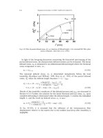
Long-Term Properties
4.6.1 Creep
4.6.1.1 Creep Data
ß 2007 by Taylor & Francis Group, LLC.
4.6.1.2 Long-Term Creep Behavior
4.6.1.3 Schapery Creep and Recovery Equations
4.6.2 Stress Rupture
4.7 Fracture Behavior and Damage Tolerance
4.7.1 Crack Growth Resistance
4.7.2 Delamination Growth Resistance
4.7.2.1 Mode I Delamination
4.7.2.2 Mode II Delamination
4.7.3 Methods of Improving Damage Tolerance
4.7.3.1 Matrix Toughness
4.7.3.2 Interleaving
4.7.3.3 Stacking Sequence
4.7.3.4 Interply Hybridization
4.7.3.5 Through-the-Thickness Reinforcement
4.7.3.6 Ply Termination
4.7.3.7 Edge Modification
References
Problems
Chapter 5
5.1
5.2
5.3
5.4
5.5
5.6
5.7
5.8
5.9
Manufacturing
Fundamentals
5.1.1 Degree of Cure
5.1.2 Viscosity
5.1.3 Resin Flow
5.1.4 Consolidation
5.1.5 Gel-Time Test
5.1.6 Shrinkage
5.1.7 Voids
Bag-Molding Process
Compression Molding
Pultrusion
Filament Winding
Liquid Composite Molding Processes
5.6.1 Resin Transfer Molding
5.6.2 Structural Reaction Injection Molding
Other Manufacturing Processes
5.7.1 Resin Film Infusion
5.7.2 Elastic Reservoir Molding
5.7.3 Tube Rolling
Manufacturing Processes for Thermoplastic Matrix Composites
Quality Inspection Methods
5.9.1 Raw Materials
5.9.2 Cure Cycle Monitoring
ß 2007 by Taylor & Francis Group, LLC.
5.9.3
Cured Composite Part
5.9.3.1 Radiography
5.9.3.2 Ultrasonic
5.9.3.3 Acoustic Emission
5.9.3.4 Acousto-Ultrasonic
5.9.3.5 Thermography
5.10 Cost Issues
References
Problems
Chapter 6
6.1
6.2
6.3
6.4
6.5
Design
Failure Prediction
6.1.1 Failure Prediction in a Unidirectional Lamina
6.1.1.1 Maximum Stress Theory
6.1.1.2 Maximum Strain Theory
6.1.1.3 Azzi–Tsai–Hill Theory
6.1.1.4 Tsai–Wu Failure Theory
6.1.2 Failure Prediction for Unnotched Laminates
6.1.2.1 Consequence of Lamina Failure
6.1.2.2 Ultimate Failure of a Laminate
6.1.3 Failure Prediction in Random Fiber Laminates
6.1.4 Failure Prediction in Notched Laminates
6.1.4.1 Stress Concentration Factor
6.1.4.2 Hole Size Effect on Strength
6.1.5 Failure Prediction for Delamination Initiation
Laminate Design Considerations
6.2.1 Design Philosophy
6.2.2 Design Criteria
6.2.3 Design Allowables
6.2.4 General Design Guidelines
6.2.4.1 Laminate Design for Strength
6.2.4.2 Laminate Design for Stiffness
6.2.5 Finite Element Analysis
Joint Design
6.3.1 Mechanical Joints
6.3.2 Bonded Joints
Design Examples
6.4.1 Design of a Tension Member
6.4.2 Design of a Compression Member
6.4.3 Design of a Beam
6.4.4 Design of a Torsional Member
Application Examples
ß 2007 by Taylor & Francis Group, LLC.
6.5.1
6.5.2
6.5.3
6.5.4
References
Problems
Inboard Ailerons on Lockheed L-1011 Aircraft
Composite Pressure Vessels
Corvette Leaf Springs
Tubes for Space Station Truss Structure
Chapter 7
Metal, Ceramic, and Carbon Matrix Composites
7.1
Metal Matrix Composites
7.1.1 Mechanical Properties
7.1.1.1 Continuous-Fiber MMC
7.1.1.2 Discontinuously Reinforced MMC
7.1.2 Manufacturing Processes
7.1.2.1 Continuously Reinforced MMC
7.1.2.2 Discontinuously Reinforced MMC
7.2 Ceramic Matrix Composites
7.2.1 Micromechanics
7.2.2 Mechanical Properties
7.2.2.1 Glass Matrix Composites
7.2.2.2 Polycrystalline Ceramic Matrix
7.2.3 Manufacturing Processes
7.2.3.1 Powder Consolidation Process
7.2.3.2 Chemical Processes
7.3 Carbon Matrix Composites
References
Problems
Chapter 8
Polymer Nanocomposites
8.1
8.2
8.3
Nanoclay
Carbon Nanofibers
Carbon Nanotubes
8.3.1 Structure
8.3.2 Production of Carbon Nanotubes
8.3.3 Functionalization of Carbon Nanotubes
8.3.4 Mechanical Properties of Carbon Nanotubes
8.3.5 Carbon Nanotube–Polymer Composites
8.3.6 Properties of Carbon Nanotube–Polymer
Composites
References
Problems
ß 2007 by Taylor & Francis Group, LLC.
Appendixes
A.1
Woven Fabric Terminology
A.2
Residual Stresses in Fibers and Matrix in a Lamina
Due to Cooling
Reference
A.3
Alternative Equations for the Elastic and Thermal
Properties of a Lamina
References
A.4
Halpin–Tsai Equations
References
A.5
Typical Mechanical Properties of Unidirectional
Continuous Fiber Composites
A.6
Properties of Various SMC Composites
A.7
Finite Width Correction Factor for Isotropic Plates
A.8
Determination of Design Allowables
A.8.1
Normal Distribution
A.8.2
Weibull Distribution
Reference
A.9
Typical Mechanical Properties of Metal Matrix Composites
A.10 Useful References
A.10.1 Text and Reference Books
A.10.2 Leading Journals on Composite Materials
A.10.3 Professional Societies Associated with Conferences
and Publications on Composite Materials
A.11 List of Selected Computer Programs
ß 2007 by Taylor & Francis Group, LLC.
Preface to the Third Edition
Almost a decade has gone by since the second edition of this book was
published. The fundamental understanding of fiber reinforcement has not
changed, but many new advancements have taken place in the materials area,
especially after the discovery of carbon nanotubes in 1991. There has also been
increasing applications of composite materials, which started mainly in the
aerospace industry in the 1950s, but now can be seen in many nonaerospace
industries, including consumer goods, automotive, power transmission, and
biomedical. It is now becoming a part of the ‘‘regular’’ materials vocabulary.
The third edition is written to update the book with recent advancements
and applications.
Almost all the chapters in the book have been extended with new information, example problems and chapter-end problems. Chapter 1 has been rewritten to show the increasing range of applications of fiber-reinforced polymers
and emphasize the material selection process. Chapter 2 has two new sections,
one on natural fibers and the other on fiber architecture. Chapter 7 has a new
section on carbon–carbon composites. Chapter 8 has been added to introduce
polymer-based nanocomposites, which are the most recent addition to the
composite family and are receiving great attention from both researchers as
well as potential users.
As before, I have tried to maintain a balance between materials, mechanics,
processing and design of fiber-reinforced composites. This book is best-suited
for senior-level undergraduate or first-level graduate students, who I believe
will be able to acquire a broad knowledge on composite materials from this
book. Numerous example problems and chapter-end problems will help them
better understand and apply the concepts to practical solutions. Numerous
references cited in the book will help them find additional research information
and go deeper into topics that are of interest to them.
I would like to thank the students, faculty and others who have used the
earlier editions of this book in the past. I have received suggestions and
encouragement from several faculty on writing the third edition—thanks to
them. Finally, the editorial and production staff of the CRC Press needs to be
acknowledged for their work and patience—thanks to them also.
P.K. Mallick
ß 2007 by Taylor & Francis Group, LLC.
ß 2007 by Taylor & Francis Group, LLC.
Author
P.K. Mallick is a professor in the Department of Mechanical Engineering and
the director of Interdisciplinary Programs at the University of Michigan-Dearborn. He is also the director of the Center for Lightweighting Automotive
Materials and Processing at the University. His areas of research interest are
mechanical properties, design considerations, and manufacturing process
development of polymers, polymer matrix composites, and lightweight alloys.
He has published more than 100 technical articles on these topics, and also
authored or coauthored several books on composite materials, including
Composite Materials Handbook and Composite Materials Technology. He is a
fellow of the American Society of Mechanical Engineers. Dr Mallick received
his BE degree (1966) in mechanical engineering from Calcutta University,
India, and the MS (1970) and PhD (1973) degrees in mechanical engineering
from the Illinois Institute of Technology.
ß 2007 by Taylor & Francis Group, LLC.
ß 2007 by Taylor & Francis Group, LLC.
1
Introduction
1.1 DEFINITION
Fiber-reinforced composite materials consist of fibers of high strength and
modulus embedded in or bonded to a matrix with distinct interfaces (boundaries) between them. In this form, both fibers and matrix retain their physical
and chemical identities, yet they produce a combination of properties that cannot
be achieved with either of the constituents acting alone. In general, fibers are the
principal load-carrying members, while the surrounding matrix keeps them in the
desired location and orientation, acts as a load transfer medium between them,
and protects them from environmental damages due to elevated temperatures
and humidity, for example. Thus, even though the fibers provide reinforcement
for the matrix, the latter also serves a number of useful functions in a fiberreinforced composite material.
The principal fibers in commercial use are various types of glass and carbon
as well as Kevlar 49. Other fibers, such as boron, silicon carbide, and aluminum
oxide, are used in limited quantities. All these fibers can be incorporated into a
matrix either in continuous lengths or in discontinuous (short) lengths. The matrix
material may be a polymer, a metal, or a ceramic. Various chemical compositions and microstructural arrangements are possible in each matrix category.
The most common form in which fiber-reinforced composites are used in
structural applications is called a laminate, which is made by stacking a number
of thin layers of fibers and matrix and consolidating them into the desired
thickness. Fiber orientation in each layer as well as the stacking sequence of
various layers in a composite laminate can be controlled to generate a wide
range of physical and mechanical properties for the composite laminate.
In this book, we focus our attention on the mechanics, performance,
manufacturing, and design of fiber-reinforced polymers. Most of the data
presented in this book are related to continuous fiber-reinforced epoxy laminates, although other polymeric matrices, including thermoplastic matrices, are
also considered. Metal and ceramic matrix composites are comparatively new,
but significant developments of these composites have also occurred. They are
included in a separate chapter in this book. Injection-molded or reaction
injection-molded (RIM) discontinuous fiber-reinforced polymers are not discussed; however, some of the mechanics and design principles included in this
book are applicable to these composites as well. Another material of great
ß 2007 by Taylor & Francis Group, LLC.
commercial interest is classified as particulate composites. The major constituents in these composites are particles of mica, silica, glass spheres, calcium
carbonate, and others. In general, these particles do not contribute to the loadcarrying capacity of the material and act more like a filler than a reinforcement
for the matrix. Particulate composites, by themselves, deserve a special attention and are not addressed in this book.
Another type of composites that have the potential of becoming an important material in the future is the nanocomposites. Even though nanocomposites
are in the early stages of development, they are now receiving a high degree of
attention from academia as well as a large number of industries, including
aerospace, automotive, and biomedical industries. The reinforcement in nanocomposites is either nanoparticles, nanofibers, or carbon nanotubes. The effective diameter of these reinforcements is of the order of 10À9 m, whereas the effective
diameter of the reinforcements used in traditional fiber-reinforced composites
is of the order of 10À6 m. The nanocomposites are introduced in Chapter 8.
1.2 GENERAL CHARACTERISTICS
Many fiber-reinforced polymers offer a combination of strength and modulus
that are either comparable to or better than many traditional metallic materials.
Because of their low density, the strength–weight ratios and modulus–weight
ratios of these composite materials are markedly superior to those of metallic
materials (Table 1.1). In addition, fatigue strength as well as fatigue damage
tolerance of many composite laminates are excellent. For these reasons, fiberreinforced polymers have emerged as a major class of structural materials and
are either used or being considered for use as substitution for metals in many
weight-critical components in aerospace, automotive, and other industries.
Traditional structural metals, such as steel and aluminum alloys, are considered isotropic, since they exhibit equal or nearly equal properties irrespective of the
direction of measurement. In general, the properties of a fiber-reinforced composite depend strongly on the direction of measurement, and therefore, they are not
isotropic materials. For example, the tensile strength and modulus of a unidirectionally oriented fiber-reinforced polymer are maximum when these properties are
measured in the longitudinal direction of fibers. At any other angle of measurement, these properties are lower. The minimum value is observed when they are
measured in the transverse direction of fibers, that is, at 908 to the longitudinal
direction. Similar angular dependence is observed for other mechanical and
thermal properties, such as impact strength, coefficient of thermal expansion
(CTE), and thermal conductivity. Bi- or multidirectional reinforcement yields a
more balanced set of properties. Although these properties are lower than the
longitudinal properties of a unidirectional composite, they still represent a
considerable advantage over common structural metals on a unit weight basis.
The design of a fiber-reinforced composite structure is considerably more
difficult than that of a metal structure, principally due to the difference in its
ß 2007 by Taylor & Francis Group, LLC.
ß 2007 by Taylor & Francis Group, LLC.
TABLE 1.1
Tensile Properties of Some Metallic and Structural Composite Materials
Materiala
SAE 1010 steel (cold-worked)
AISI 4340 steel (quenched and tempered)
6061-T6 aluminum alloy
7178-T6 aluminum alloy
Ti-6A1-4V titanium alloy (aged)
17-7 PH stainless steel (aged)
INCO 718 nickel alloy (aged)
High-strength carbon fiber–epoxy
matrix (unidirectional)a
High-modulus carbon fiber–epoxy
matrix (unidirectional)
E-glass fiber–epoxy matrix (unidirectional)
Kevlar 49 fiber–epoxy matrix (unidirectional)
Boron fiber-6061 A1 alloy matrix (annealed)
Carbon fiber–epoxy matrix (quasi-isotropic)
Sheet-molding compound (SMC)
composite (isotropic)
a
Density,
g=cm3
Modulus,
GPa (Msi)
Tensile Strength,
MPa (ksi)
Yield Strength,
MPa (ksi)
Ratio of Modulus
to Weight,b 106 m
Ratio of Tensile
Strength to
Weight,b 103 m
7.87
7.87
2.70
2.70
4.43
7.87
8.2
1.55
207 (30)
207 (30)
68.9 (10)
68.9 (10)
110 (16)
196 (28.5)
207 (30)
137.8 (20)
365 (53)
1722 (250)
310 (45)
606 (88)
1171 (170)
1619 (235)
1399 (203)
1550 (225)
303 (44)
1515 (220)
275 (40)
537 (78)
1068 (155)
1515 (220)
1247 (181)
—
2.68
2.68
2.60
2.60
2.53
2.54
2.57
9.06
4.72
22.3
11.7
22.9
26.9
21.0
17.4
101.9
1.63
215 (31.2)
1240 (180)
—
13.44
77.5
1.85
1.38
2.35
1.55
1.87
39.3 (5.7)
75.8 (11)
220 (32)
45.5 (6.6)
15.8 (2.3)
965 (140)
1378 (200)
1109 (161)
579 (84)
164 (23.8)
—
—
—
—
2.16
5.60
9.54
2.99
0.86
53.2
101.8
48.1
38
8.9
For unidirectional composites, the fibers are unidirectional and the reported modulus and tensile strength values are measured in the direction of fibers,
that is, the longitudinal direction of the composite.
b
The modulus–weight ratio and the strength–weight ratios are obtained by dividing the absolute values with the specific weight of the respective material.
Specific weight is defined as weight per unit volume. It is obtained by multiplying density with the acceleration due to gravity.
properties in different directions. However, the nonisotropic nature of a fiberreinforced composite material creates a unique opportunity of tailoring its
properties according to the design requirements. This design flexibility can be
used to selectively reinforce a structure in the directions of major stresses,
increase its stiffness in a preferred direction, fabricate curved panels without
any secondary forming operation, or produce structures with zero coefficients
of thermal expansion.
The use of fiber-reinforced polymer as the skin material and a lightweight
core, such as aluminum honeycomb, plastic foam, metal foam, and balsa wood,
to build a sandwich beam, plate, or shell provides another degree of design
flexibility that is not easily achievable with metals. Such sandwich construction
can produce high stiffness with very little, if any, increase in weight. Another
sandwich construction in which the skin material is an aluminum alloy and the
core material is a fiber-reinforced polymer has found widespread use in aircrafts
and other applications, primarily due to their higher fatigue performance and
damage tolerance than aluminum alloys.
In addition to the directional dependence of properties, there are a number
of other differences between structural metals and fiber-reinforced composites.
For example, metals in general exhibit yielding and plastic deformation. Most
fiber-reinforced composites are elastic in their tensile stress–strain characteristics. However, the heterogeneous nature of these materials provides mechanisms for energy absorption on a microscopic scale, which is comparable to the
yielding process. Depending on the type and severity of external loads, a
composite laminate may exhibit gradual deterioration in properties but usually
would not fail in a catastrophic manner. Mechanisms of damage development
and growth in metal and composite structures are also quite different and must
be carefully considered during the design process when the metal is substituted
with a fiber-reinforced polymer.
Coefficient of thermal expansion (CTE) for many fiber-reinforced composites
is much lower than that for metals (Table 1.2). As a result, composite structures
may exhibit a better dimensional stability over a wide temperature range. However, the differences in thermal expansion between metals and composite materials
may create undue thermal stresses when they are used in conjunction, for example,
near an attachment. In some applications, such as electronic packaging, where
quick and effective heat dissipation is needed to prevent component failure or
malfunctioning due to overheating and undesirable temperature rise, thermal
conductivity is an important material property to consider. In these applications,
some fiber-reinforced composites may excel over metals because of the combination of their high thermal conductivity–weight ratio (Table 1.2) and low CTE. On
the other hand, electrical conductivity of fiber-reinforced polymers is, in general,
lower than that of metals. The electric charge build up within the material because
of low electrical conductivity can lead to problems such as radio frequency
interference (RFI) and damage due to lightning strike.
ß 2007 by Taylor & Francis Group, LLC.
TABLE 1.2
Thermal Properties of a Few Selected Metals and Composite Materials
Material
Plain carbon steels
Copper
Aluminum alloys
Ti-6Al-4V titanium alloy
Invar
K1100 carbon fiber–epoxy matrix
Glass fiber–epoxy matrix
SiC particle-reinforced aluminum
Density
(g=cm3)
7.87
8.9
2.7
4.43
8.05
1.8
2.1
3
Coefficient
of Thermal
Expansion
(10À6=8C)
11.7
17
23.5
8.6
1.6
À1.1
11–20
6.2–7.3
Thermal
Conductivity
(W=m8K)
Ratio of
Thermal
Conductivity
to Weight
(10À3 m4=s3 8K)
52
388
130–220
6.7
10
300
0.16–0.26
170–220
6.6
43.6
48.1–81.5
1.51
1.24
166.7
0.08–0.12
56.7–73.3
Another unique characteristic of many fiber-reinforced composites is their
high internal damping. This leads to better vibrational energy absorption
within the material and results in reduced transmission of noise and vibrations
to neighboring structures. High damping capacity of composite materials can
be beneficial in many automotive applications in which noise, vibration, and
harshness (NVH) are critical issues for passenger comfort. High damping
capacity is also useful in many sporting goods applications.
An advantage attributed to fiber-reinforced polymers is their noncorroding
behavior. However, many fiber-reinforced polymers are capable of absorbing
moisture or chemicals from the surrounding environment, which may create
dimensional changes or adverse internal stresses in the material. If such behavior is undesirable in an application, the composite surface must be protected
from moisture or chemicals by an appropriate paint or coating. Among other
environmental factors that may cause degradation in the mechanical properties
of some polymer matrix composites are elevated temperatures, corrosive fluids,
and ultraviolet rays. In metal matrix composites, oxidation of the matrix as well
as adverse chemical reaction between fibers and the matrix are of great concern
in high-temperature applications.
The manufacturing processes used with fiber-reinforced polymers are different from the traditional manufacturing processes used for metals, such as
casting, forging, and so on. In general, they require significantly less energy and
lower pressure or force than the manufacturing processes used for metals. Parts
integration and net-shape or near net-shape manufacturing processes are also
great advantages of using fiber-reinforced polymers. Parts integration reduces
the number of parts, the number of manufacturing operations, and also, the
number of assembly operations. Net-shape or near net-shape manufacturing
ß 2007 by Taylor & Francis Group, LLC.
processes, such as filament winding and pultrusion, used for making many
fiber-reinforced polymer parts, either reduce or eliminate the finishing operations such as machining and grinding, which are commonly required as
finishing operations for cast or forged metallic parts.
1.3 APPLICATIONS
Commercial and industrial applications of fiber-reinforced polymer composites
are so varied that it is impossible to list them all. In this section, we highlight
only the major structural application areas, which include aircraft, space,
automotive, sporting goods, marine, and infrastructure. Fiber-reinforced polymer composites are also used in electronics (e.g., printed circuit boards),
building construction (e.g., floor beams), furniture (e.g., chair springs), power
industry (e.g., transformer housing), oil industry (e.g., offshore oil platforms and
oil sucker rods used in lifting underground oil), medical industry (e.g., bone plates
for fracture fixation, implants, and prosthetics), and in many industrial products, such as step ladders, oxygen tanks, and power transmission shafts. Potential use of fiber-reinforced composites exists in many engineering fields. Putting
them to actual use requires careful design practice and appropriate process
development based on the understanding of their unique mechanical, physical,
and thermal characteristics.
1.3.1 AIRCRAFT
AND
MILITARY APPLICATIONS
The major structural applications for fiber-reinforced composites are in the
field of military and commercial aircrafts, for which weight reduction is critical
for higher speeds and increased payloads. Ever since the production application
of boron fiber-reinforced epoxy skins for F-14 horizontal stabilizers in 1969,
the use of fiber-reinforced polymers has experienced a steady growth in the
aircraft industry. With the introduction of carbon fibers in the 1970s, carbon
fiber-reinforced epoxy has become the primary material in many wing, fuselage,
and empennage components (Table 1.3). The structural integrity and durability
of these early components have built up confidence in their performance and
prompted developments of other structural aircraft components, resulting in an
increasing amount of composites being used in military aircrafts. For example,
the airframe of AV-8B, a vertical and short take-off and landing (VSTOL)
aircraft introduced in 1982, contains nearly 25% by weight of carbon fiberreinforced epoxy. The F-22 fighter aircraft also contains ~25% by weight of
carbon fiber-reinforced polymers; the other major materials are titanium (39%)
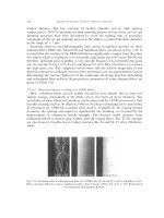
and aluminum (16%). The outer skin of B-2 (Figure 1.1) and other stealth
aircrafts is almost all made of carbon fiber-reinforced polymers. The stealth
characteristics of these aircrafts are due to the use of carbon fibers, special
coatings, and other design features that reduce radar reflection and heat
radiation.
ß 2007 by Taylor & Francis Group, LLC.
TABLE 1.3
Early Applications of Fiber-Reinforced Polymers in Military Aircrafts
Aircraft
F-14 (1969)
F-11
F-15 (1975)
F-16 (1977)
F=A-18 (1978)
AV-8B (1982)
Component
Material
Overall Weight
Saving Over
Metal Component (%)
Skin on the horizontal stabilizer
box
Under the wing fairings
Fin, rudder, and stabilizer skins
Skins on vertical fin box, fin
leading edge
Wing skins, horizontal and
vertical tail boxes; wing and
tail control surfaces, etc.
Wing skins and substructures;
forward fuselage; horizontal
stabilizer; flaps; ailerons
Boron fiber–epoxy
19
Carbon fiber–epoxy
Boron fiber–epoxy
Carbon fiber–epoxy
25
23
Carbon fiber–epoxy
35
Carbon fiber–epoxy
25
Source: Adapted from Riggs, J.P., Mater. Soc., 8, 351, 1984.
The composite applications on commercial aircrafts began with a few
selective secondary structural components, all of which were made of a highstrength carbon fiber-reinforced epoxy (Table 1.4). They were designed and
produced under the NASA Aircraft Energy Efficiency (ACEE) program and
were installed in various airplanes during 1972–1986 [1]. By 1987, 350 composite components were placed in service in various commercial aircrafts, and over
the next few years, they accumulated millions of flight hours. Periodic inspection and evaluation of these components showed some damages caused by
ground handling accidents, foreign object impacts, and lightning strikes.
FIGURE 1.1 Stealth aircraft (note that the carbon fibers in the construction of the
aircraft contributes to its stealth characteristics).
ß 2007 by Taylor & Francis Group, LLC.