Programmable logic controller training course
Bạn đang xem bản rút gọn của tài liệu. Xem và tải ngay bản đầy đủ của tài liệu tại đây (2.01 MB, 110 trang )
Programmable Logic
Controller Training Course
PLC Fundamentals and Applications
Ali T. Shaheen
University of Baghdad
Electrical Eng. Dept.
2011
PLC Training Course
Ali T. Shaheen
Lecture 1
Introduction to PLC and Types of Control System
A programmable controller, formally called the programmable logic controller
(PLC) can be defined as a solid state device member of the computer family.
It is capable of storing instruction to implement control functions such as
sequencing, timing, counting, arithmetic, data manipulation and communication to
control industrial machines and processes.
PLC can perform the same task as hard-wired devices
Connections between field devices and relay contacts take place in the PLC
Installation is less extensive
Also more complex function.
2
PLC Training Course
Ali T. Shaheen
History of PLC
During the Industrial Revolution of the 18th-and 19th-centuries, many
traditionally manual processes were taken over by machines. These early
machines relied on gears and pulleys to work and were, by our standards,
extremely primitive. The first major breakthrough in the development of
control systems came with the invention of electrically powered machines.
The first control systems were developed in the early years of the 20th
century and used sequential Relay Circuits for machine control. A major
technical breakthrough in its day, and still used in some plants today, relay
technology enabled machines to work faster and more safely.
Relay circuits performed their job very well, but they required large amounts
of floor space, and huge amounts of energy. Adding to their drawbacks as the
basis for a machine control system, relay circuits also took a long time to
install, troubleshoot, and modify. Finally, in the early 1970s, a device was
developed to replace sequential relay circuits: the Programmable Logic
Controller (PLC).
As you will remember from reading about them in Module 24, PLCs are more
reliable, faster, more flexible and more efficient than relay-based systems.
For example, PLCs are cheaper and easier to wire and maintain than relays.
Furthermore, when it comes to troubleshooting, PLCs are much quicker than
relays at testing and debugging the program.
PLCs are used in all kinds of industries. In fact, almost any industrial process
that uses electrical control needs a PLC. For example, let's assume that when
a switch turns on we want to turn a solenoid on for 5 seconds and then turn it
off regardless of how long the switch is on. We can do this with a simple
3
PLC Training Course
Ali T. Shaheen
external timer. But what if the process included 10 switches and solenoids?
We would need 10 external timers. What if the process also needed to count
how many times the switches individually turned on?
We need a lot of external counters. With a PLC, however, we can dispense
with those unwieldy timers and counters, and simply program the PLC to
count its inputs and turn the solenoids on for the specified time.
Comparison of PLC with Other Control Systems :-
Relay
Digital
Computers
PLC systems
systems
Logics
Physical Size
Bulky
Very Compact
Fairly Compact
Very Compact
Operating Speed
Slow
Very Fast
Fairly Fast
Fast
Noise Immunity
Excellent
Good
Fairly Good
Good
Complex
None
Yes
Yes
Yes
Ease of Changes
Very Difficult
Difficult
Quite Simple
Very Simple
Easy of
Poor-large No.
Poor if ICs
Poor-several
Good-few
Maintenance
Of Contacts
Soldered
Custom Boards
Standard Cards
C\Cs
Operation
4
PLC Training Course
Ali T. Shaheen
Advantages of PLCs: The same, as well as more complex tasks, can be done with a PLC. Wiring between
devices and relay contacts is done in the PLC program. Hard-wiring, though still
required to connect field devices, is less intensive. Modifying the application and
correcting errors are easier to handle. It is easier to create and change a program in a
PLC than it is to wire and rewire a circuit.
Following are just a few of the advantages of PLCs: • Smaller physical size than hard-wire solutions.
• Easier and faster to make changes.
• PLCs have integrated diagnostics and override functions.
• Diagnostics are centrally available.
• Applications can be immediately documented.
• Applications can be duplicated faster and less expensively.
Basic elements of PLC and their functions
1.1 - Switch Circuit Types : -
5
PLC Training Course
Ali T. Shaheen
The Following diagrams are circuit configuration for 2- and 3-pole safety switches.
Safety switches may be fusible, non-fusible, or fusible with a solid neutral.
The circuit configuration required depends on the load and on the power supply
connected to it. For example, a three-phase motor needs a 3-pole switch to connect
it to a three-phase power supply. If over current protection is required, a fusible
3-pole safety switch should be selected, as in the following example.
6
PLC Training Course
Ali T. Shaheen
Selecting a Switch: There are three important features to consider when selecting a switch:
Contacts (e.g. single pole, double throw)
Ratings (maximum voltage and current)
Method of Operation (toggle, slide, key etc.)
Switch Contacts: Several terms are used to describe switch contacts:
Pole - number of switch contact sets.
Throw - number of conducting positions, single or double.
Way - number of conducting positions, three or more.
Momentary - switch returns to its normal position when released.
Open - off position, contacts not conducting.
7
PLC Training Course
Ali T. Shaheen
Closed - on position, contacts conducting, there may be several on positions.
For example: the simplest on-off switch has one set of contacts (single pole) and
one switching position which conducts (single throw). The switch mechanism has
two positions: open (off) and closed (on), but it is called 'single throw' because
only one position conducts.
Switch Contact Ratings: Switch contacts are rated with a maximum voltage and current, and there may be
different ratings for AC and DC. The AC values are higher because the current
falls to zero many times each second and an arc is less likely to form across the
switch contacts.
For low voltage electronics projects the voltage rating will not matter, but you may
need to check the current rating. The maximum current is less for inductive loads
(coils and motors) because they cause more sparking at the contacts when switched
off.
8
PLC Training Course
Ali T. Shaheen
Standard Switches : Type of Switch
Circuit Symbol
Example
ON-OFF
Single Pole, Single Throw = SPST
A simple on-off switch. This type can be used to
switch the power supply to a circuit.
When used with mains electricity this type of
switch must be in the live wire, but it is better to
SPST toggle switch
use a DPST switch to isolate both live and
neutral.
(ON)-OFF
Push-to-make = SPST Momentary
A push-to-make switch returns to its normally
Push-to-make switch
open (off) position when you release the button,
this is shown by the brackets around ON. This is
the standard doorbell switch.
Push-to-break switch
ON-(OFF)
9
PLC Training Course
Ali T. Shaheen
Push-to-break = SPST Momentary
A push-to-break switch returns to its normally
closed (on) position when you release the button.
ON-ON
Single Pole, Double Throw = SPDT
This switch can be on in both positions,
switching on a separate device in each case. It is
often called a changeover switch. For example, a
SPDT switch can be used to switch on a red lamp
in one position and a green lamp in the other
position.
SPDT toggle switch
A SPDT toggle switch may be used as a simple
on-off switch by connecting to COM and one of
the A or B terminals shown in the diagram. A
and B are interchangeable so switches are usually
not labeled.
ON-OFF-ON
SPDT Centre Off
SPDT slide switch
(PCB mounting)
A special version of the standard SPDT switch. It
has a third switching position in the centre which
is off. Momentary (ON)-OFF-(ON) versions are
also available where the switch returns to the
central off position when released.
SPDT rocker switch
10
PLC Training Course
Ali T. Shaheen
Dual ON-OFF
Double Pole, Single Throw = DPST
A pair of on-off switches which operate together
(shown by the dotted line in the circuit symbol).
A DPST switch is often used to switch mains
DPST rocker switch
electricity because it can isolate both the live and
neutral connections.
Dual ON-ON
Double Pole, Double Throw = DPDT
A pair of on-on switches which operate together
(shown by the dotted line in the circuit symbol).
A DPDT switch can be wired up as a reversing
switch for a motor as shown in the diagram.
DPDT slide switch
ON-OFF-ON
DPDT Centre Off
A special version of the standard SPDT switch. It
has a third switching position in the centre which
is off. This can be very useful for motor control
because you have forward, off and reverse
positions. Momentary (ON)-OFF-(ON) versions
Wiring for Reversing Switch
are also available where the switch returns to the
central off position when released.
Special Switches : -
11
PLC Training Course
Type of Switch
Ali T. Shaheen
Example
Push-Push Switch (e.g. SPST = ON-OFF)
This looks like a momentary action push switch but it is a
standard on-off switch: push once to switch on, push again
to switch off. This is called a latching action.
Micro switch (usually SPDT = ON-ON)
Micro switches are designed to switch fully open or closed
in response to small movements. They are available with
levers and rollers attached.
Key switch
A key operated switch. The example shown is SPST.
Tilt Switch (SPST)
Tilt switches contain a conductive liquid and when tilted
this bridges the contacts inside, closing the switch. They
can be used as a sensor to detect the position of an object.
Some tilt switches contain mercury which is poisonous.
12
PLC Training Course
Ali T. Shaheen
Reed Switch (usually SPST)
The contacts of a reed switch are closed by bringing a
small magnet near the switch. They are used in security
circuits, for example to check that doors are closed.
Standard reed switches are SPST (simple on-off) but SPDT
(changeover) versions are also available.
Warning: reed switches have a glass body which is easily
broken!
DIP Switch (DIP = Dual In-line Parallel)
This is a set of miniature SPST on-off switches, the
example shown has 8 switches. The package is the same
size as a standard DIL (Dual In-Line) integrated circuit.
This type of switch is used to set up circuits, e.g. setting
the code of a remote control.
Multi-pole Switch
The picture shows a 6-pole double throw switch, also
known as a 6-pole changeover switch. It can be set to have
momentary or latching action. Latching action means it
behaves as a push-push switch, push once for the first
position, push again for the second position etc.
Multi-way Switch
Multi-way switches have 3 or more conducting positions.
They may have several poles (contact sets). A popular type
13
PLC Training Course
Ali T. Shaheen
has a rotary action and it is available with a range of
Multi-way rotary switch
contact arrangements from 1-pole 12-way to 4-pole 3 way.
The number of ways (switch positions) may be reduced by
adjusting a stop under the fixing nut. For example if you
need a 2-pole 5-way switch you can buy the 2-pole 6-way
version and adjust the stop.
1-pole 4-way switch symbol
Contrast this multi-way switch (many switch positions) with
the multi-pole switch (many contact sets) described above.
Sensors:-
Generally there are 5 steps to determine which switch type is best suited to the
application. This depends on the material properties of the target to be detected.
Step ( 1 ) : -
type of sensor .
Step ( 2 ) : -
Housing design .
Step ( 3 ) : -
Sensing range (mm)
Step ( 4 ) : -
Electrical data and connections
Step ( 5 ) : -
General specifications
Proximity Sensor:
A type of sensing switch that detects the presence or absence of an object without
physical contact
14
PLC Training Course
Ali T. Shaheen
Inductive Proximity Sensor:-
A type of sensing switch that uses an electromagnetic coil to detect the presence of
a metal object without coming into physical contact with it, Inductive proximity
sensors ignore nonmetallic objects.
Capacitive Proximity Sensor :A type of sensing switch that produces an electrostatic field to detect the presence
of metal and nonmetallic objects without coming into contact with them
15
PLC Training Course
Ali T. Shaheen
Ultrasonic Sensor
A type of sensing switch that uses high frequency sound to detect the presence of
an object without coming into contact with the object
Photoelectric Sensor : -
Recognition, detection, positioning, classification, counting, notification and
monitoring. Nowadays, these processes are largely handled by non-contact
photoelectric sensors. Applications range from the automobile industry,
mechanical engineering, and assembly automation, through warehousing and
conveyor systems and packaging applications, to the printing and paper industries,
and naturally include monitoring and safety systems.
16
PLC Training Course
Ali T. Shaheen
17
PLC Training Course
Ali T. Shaheen
Pressure Switch : -
A control device that opens or closes its contacts in response to a change in the
pressure of a liquid or gas
Sensing Switches :-
A device, often called a sensor, used to provide information on the presence or
absence of an object. Examples include a limit switch, photoelectric sensor,
inductive proximity sensor, capacitive proximity sensor, and ultrasonic proximity
sensor.
Sensors
Limit Switch
Advantages
Disadvantage
Applications
High Current Capability
Require Physical Contact
Interlocking
Low Cost
Very Slow Response
Basic End Travel
Familiar " Low-Tech "
Contact Bounce
Sensing
Sensing
18
PLC Training Course
Ali T. Shaheen
Senses all Kinds of
Photoelectric
Materials
Long Life
Largest Sensing Range
Lens Subject to
Packaging
Contamination.
Material Handling
Parts Detection
Industrial and
Sensing Range Affected
by Color and Reflectivity
Very Fast Response Time
Resistant to Harsh
Inductive
Environments
Distance Limitations
Senses Metal Only
Very Predictable
Machines.
Machine Tools
Level Sensing
Level Control
Doors
Anti-Collision
Long Life
Easy to Install
Can Detect Non-Metallic
Capacitive
Detects Through Some
Extreme Environmental
Changes
Containers
Senses all Materials
Very Sensitive to
Sensitive to Temperature
Changes.
Ultrasonic
Electromagnetic Relay : Relay is an electrically operated switch. Current flowing through the coil of the
relay creates a magnetic field which attracts a lever and changes the switch
contacts. The coil current can be on or off so relays have two switch positions and
they are double throw (changeover) switches.
Circuit symbol for a relay
19
PLC Training Course
Ali T. Shaheen
Relays allow one circuit to switch a second circuit which can be completely separate from
the first. For example a low voltage battery circuit can use a relay to switch a 230V AC
mains circuit. There is no electrical connection inside the relay between the two circuits,
the link is magnetic and mechanical. The coil of a relay passes a relatively large current,
typically 30mA for a 12V relay, but it can be as much as 100mA for relays designed to
operate from lower voltages
Relays are usually SPDT or DPDT but they can have many more sets of switch contacts,
for example relays with 4 sets of changeover contacts are readily available.
The animated picture shows a working relay with its coil and switch contacts. You can see
a lever on the left being attracted by magnetism when the coil is switched on. This lever
moves the switch contacts. There is one set of contacts (SPDT) in the foreground and
another behind them, making the relay DPDT.
The relay's switch connections are usually labeled COM, NC and NO:
COM = Common, always connect to this, it is the moving part of the switch.
NC = Normally Closed, COM is connected to this when the relay coil is off.
NO = Normally Open, COM is connected to this when the relay coil is on.
20
PLC Training Course
Ali T. Shaheen
Connect to COM and NO if you want the switched circuit to be on when the relay
coil is on.
Connect to COM and NC if you want the switched circuit to be on when the relay
coil is off.
Choosing a relay : You need to consider several features when choosing a relay:
1. Physical size and pin arrangement
If you are choosing a relay for an existing PCB you will need to ensure that its
dimensions and pin arrangement are suitable. You should find this information in the
supplier's catalogue.
2. Coil voltage
The relay's coil voltage rating and resistance must suit the circuit powering the relay
coil. Many relays have a coil rated for a 12V supply but 5V and 24V relays are also
readily available. Some relays operate perfectly well with a supply voltage which is a
little lower than their rated value.
3. Coil resistance
The circuit must be able to supply the current required by the relay coil. You can use
Ohm's law to calculate the current:
supply voltage
Relay coil current =
coil resistance
4. For example: A 12V supply relay with a coil resistance of 400
passes a current of
21
PLC Training Course
Ali T. Shaheen
30mA.
5. Switch ratings (voltage and current)
The relay's switch contacts must be suitable for the circuit they are to control. You
will need to check the voltage and current ratings. Note that the voltage rating is
usually higher for AC, for example: "5A at 24V DC or 125V AC".
6. Switch contact arrangement (SPDT, DPDT etc)
Most relays are SPDT or DPDT which are often described as "single pole
changeover" (SPCO) or "double pole changeover" (DPCO)
example).
Advantages of relays:
Relays can switch AC and DC, transistors can only switch DC.
Relays can switch high voltages, transistors cannot.
Relays are a better choice for switching large currents (> 5A).
Relays can switch many contacts at once.
Disadvantages of relays:
Relays are bulkier than transistors for switching small currents.
Relays cannot switch rapidly (except reed relays), transistors can switch many times
per second.
Relays use more power due to the current flowing through their coil.
Relays require more current than many chips can provide, so a low power transistor
may be needed to switch the current for the relay's coil.
22
PLC Training Course
Ali T. Shaheen
Relays can generate a very high voltage across the coil when switched off. This can
damage other components in the circuit. To prevent this a diode is connected across the
coil. The cathode of the diode is connected to the most positive end of the coil.
Overload Relay
A device used to protect a motor from damage resulting from an overcurrent.
Overcurrent
A current in excess of the rated current for a device or conductor. An overcurrent
can result from an overload, short circuit, or ground fault.
Overload
Can refer to an operating condition in excess of a full-load rating or a current high
enough to cause damage if it is present long enough. An overload does not refer to
a short circuit or ground fault.
23
PLC Training Course
Ali T. Shaheen
Lecture 2
Digital Logic Concepts
Number systems
Since a PLC is a computer, it stores information in the form of On or Off
conditions (1 or 0), referred to as binary digits (bits). Sometimes binary digits are
used individually and sometimes they are used to represent numerical values.
Decimal System Various number systems are used by PLCs. All number systems
have the same three characteristics: digits, base, weight. The decimal system,
which is commonly used in everyday life, has the following characteristics: Ten
digits 0, 1, 2, 3, 4, 5, 6, 7, 8, 9 Base 10 Weights 1, 10, 100, 1000,
Binary System The binary system is used by programmable controllers. The
binary system has the following characteristics:
Two digits 0, 1
Base 2
Weights Powers of base 2 (1, 2, 4, 8, 16, ...)
In the binary system 1s and 0s are arranged into columns. Each column is
weighted. The first column has a binary weight of
20. This is equivalent to a decimal 1. This is referred to as the least significant bit.
The binary weight is doubled with each succeeding column. The next column, for
example, has a weight of 21, which is equivalent to a decimal 2. The decimal value
is doubled in each successive column. The number in the far left hand column is
referred to as the most significant bit. In this example, the most significant bit has a
binary weight of 27. This is equivalent to a decimal 128.
24
PLC Training Course
Ali T. Shaheen
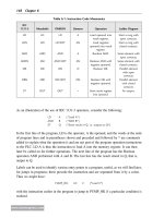
Converting Binary to Decimal
The following steps can be used to interpret a decimal number from a binary
value.
1) Search from least to most significant bit for 1s.
2) Write down the decimal representation of each column containing a 1.
3) Add the column values.
In the following example, the fourth and fifth columns from the right contain a 1.
The decimal value of the fourth column from the right is 8, and the decimal value
of the fifth column from the right is 16. The decimal equivalent of this binary
number is 24. The sum of all the weighted columns that contain a 1 is the decimal
number that the PLC has stored.
25