Digital design C to RTL
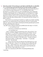
Bạn đang xem bản rút gọn của tài liệu. Xem và tải ngay bản đầy đủ của tài liệu tại đây (1.41 MB, 37 trang )
Principles Of
Digital Design
C to RTL
Control/Data flow graphs
Finite-state-machine with data
IP design
Component selection
Connection selection
Operator and variable mapping
Scheduling and pipelining
Copyright © 2010-20011 by Daniel D. Gajski
EECS31/CSE31/, University of California, Irvine
Topic preview
3
Boolean
algebra
3
Logic gates and
flip-flops
6
Finite-state
machine
Binary system
and data
representation
Sequential design
techniques
2
5
Combinational
components
Generalized
finite-state
machines
6
4
Logic design
techniques
Storage
components
8
7
8
Register-transfer
design
9
Processor
components
Copyright © 2010-20011 by Daniel D. Gajski
2
EECS31/CSE31/, University of California, Irvine
Register-transfer-level design
Each standard or custom IP components consists
of one or more datapaths and control units.
To synthesize such IP we use the models of a
CDFG and FSMD.
We demonstrate IP synthesis (RTL Design)
including
component and connectivity selection,
expression mapping
scheduling and pipelining
Copyright © 2010-20011 by Daniel D. Gajski
3
EECS31/CSE31/, University of California, Irvine
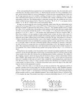
Motivation: Ones-counter
Start
Input
Control
signals
Control
unit
Data=0
Done
Problem:
Data
Mask
Temp
Ocount
Generate controller & control words for given FSMD & Datapath
Output
20-bit control words
Start = 0
s0
Done=1;
s1
Data = Input
S
1
0
Selector
Start = 1
s2
/ 0
Data =
Data = 0
Copyright © 2010-20011 by Daniel D. Gajski
Ocount = 0
s3
Mask = 1
s4
Temp = Data AND Mask
s5
Ocount = Ocount + Temp
s6
Data = Data >> 1
s7
Done=1; Output =Ocount
4
3
3
3
WA
WE
8Xm
register
file
RAA
REA
M
S1
S0
S2
S1
S0
RAB
REB
A
B
ALU
“0”
“0”
IL
IR
Shifter
EECS31/CSE31/, University of California, Irvine
Ones Counter from C Code
•Programming language semantics
• Sequential execution,
• Coding style to minimize coding
01:
•HW design
• Parallel execution,
• Communication through signals
01:
int OnesCounter(int Data){
while(1) {
02:
while (Start == 0);
03:
Done = 0;
04:
Data = Input;
05:
Ocount = 0;
02:
int Ocount = 0;
06:
Mask = 1;
03:
int Temp, Mask = 1;
07:
while (Data>0) {
04:
while (Data > 0) {
08:
Temp = Data & Mask;
05:
Temp = Data & Mask;
09:
Ocount = Ocount + Temp;
06
Ocount = Data + Temp;
10:
Data >>= 1;
07:
Data >>= 1;
11:
}
08:
}
12:
Output = Ocount;
09:
return Ocount;
13:
Done = 1;
10:
}
14:
Function-based C code
Copyright © 2010-20011 by Daniel D. Gajski
5
}
RTL-based C code
EECS31/CSE31/, University of California, Irvine
CDFG for Ones Counter
01:
while(1) {
02:
while (Start == 0);
03:
Done = 0;
04:
Data = Input;
05:
Ocount = 0;
06:
Mask = 1;
07:
while (Data>0) {
08:
Temp = Data & Mask;
09:
Ocount = Ocount + Temp;
10:
Data >>= 1;
Control/Data flow graph
0
Start
1
Input
Data Mask Ocount Done
0
1
0
Data Mask Ocount Done
>>1
Data
Output = Ocount;
13:
Done = 1;
14:
•Explicit dependencies
+
Ocount Done
Data
}
12:
•Loops, ifs, basic blocks
(BBs)
•Control dependences
between BBs
&
11:
•Resembles programming
language
>0
0
1
•Data dependences
inside BBs
•Missing dependencies
between BBs
Output Done
}
RTL-based C code
Copyright © 2010-20011 by Daniel D. Gajski
CDFG
6
EECS31/CSE31/, University of California, Irvine
CDFG to FSMD for Ones Counter
Start = 0
Start = 0
S0
S0
0
Start
Start = 1
Start = 1
Data Mask Ocount Done
1
0
0
S2
Data = Input
Ocount = 0;
Mask = 1;
Done = 0;
Data Mask Ocount Done
&
>>1
Data
S1
Done = 0; Data = Input
S2
Ocount = 0
S3
Mask = 1
S4
Temp = Data AND Mask
S5
Ocount = Ocount + Temp
S6
Data = Data >> 1
S7
Done = 1; Output = Ocount
1
Input
+
Ocount Done
Data
Data =/ 0
S5
Temp = Data AND Mask;
Ocount = Ocount + Temp;
Data = Data >> 1
Data =/ 0
>0
0
Data = 0
1
Data = 0
S7
Output = Ocount;
Done = 1;
Output Done
CDFG
Copyright © 2010-20011 by Daniel D. Gajski
Super-state FSMD
7
Cycle-accurate FSMD
EECS31/CSE31/, University of California, Irvine
FSMD for Ones Counter
Start = 0
S0
•FSMD more detailed then CDFG
Start = 1
S1
Done = 0; Data = Input
•Conditionals and statements executed
concurrently
S2
Ocount = 0
• All statement in each state executed
concurrently
S3
Mask = 1
•Control signal and variable assignments
executed concurrently
S4
Temp = Data AND Mask
S5
Ocount = Ocount + Temp
S6
Data = Data >> 1
S7
Done = 1; Output = Ocount
•States may represent clock cycles
•FSMD includes scheduling
Data =/ 0
•FSMD doesn't specify binding or
connectivity
Data = 0
Copyright © 2010-20011 by Daniel D. Gajski
8
EECS31/CSE31/, University of California, Irvine
FSMD Definition
We defined an FSM as a quintuple < S, I, O, f, h > where S is a set of
states, I and O are the sets of input and output symbols:
f:S×I
More precisely,
S ,
and
h:S
O
I = A1 × A2 ×… Ak
S = Q 1 × Q2 × … Qm
O = Y1 × Y2 ×… Yn
Where Ai, is an input signal, Qi, is the state register output and Yi, is
an output signal.
To define a FSMD, we define a set of variables, V = V1 × V2 ×…Vq ,
which defines the state of the datapath by defining the values of all
variables in each state with the set of expressions Expr(V):
Expr(V) = Const U V U {ei # ej | ei, ej el of Expr(V), # is an operation}
Notes: 1. Status signal is a signal in I;
2. Control signals are signals in O;
3. Datapath inputs and outputs are variables in V
Copyright © 2010-20011 by Daniel D. Gajski
9
EECS31/CSE31/, University of California, Irvine
RTL Design Model
Control
inputs
Control
unit
Datapath
inputs
Control
signals
Status
signals
Control
outputs
High-level block diagram
Datapath
Datapath
outputs
Datapath
inputs
Control
inputs
D
Q
D
Q
Next-state
logic
D
Selector
Register
RF
Mem
.
.
.
.
.
.
.
.
.
Control
signals
Bus 1
Bus 2
Q
State
register
*/÷
ALU
Output
logic
Status
signals
Bus 3
Out Reg
Control unit
Datapath
Control
outputs
Datapath
outputs
Register-transfer-level block diagram
Copyright © 2010-20011 by Daniel D. Gajski
10
EECS31/CSE31/, University of California, Irvine
RTL Design Model
Control
inputs
Control
unit
Datapath
inputs
Control
signals
Status
signals
Control
outputs
High-level block diagram
Datapath
Datapath
outputs
Datapath
inputs
Control
inputs
Control
signals
Selector
Register
Mem
.
.
.
.
.
.
Next-address
logic
RF
Program
Counter
Bus 1
Bus 2
*/÷
ALU
Program
Memory
Status
signals
Bus 3
Out Reg
Control unit
Datapath
Control
outputs
Datapath
outputs
Register-transfer-level block diagram
Copyright © 2010-20011 by Daniel D. Gajski
11
EECS31/CSE31/, University of California, Irvine
C-to-RTL design
RTL generation requires definition of
controller
datapath
RTL generation of a controller requires choice of
state register (program counter)
output logic (program memory)
next-state logic (next-address generator)
RTL generation of a datapath
RTL component and connectivity selection,
expression mapping (variable and operation mapping)
scheduling and pipelining
Copyright © 2010-20011 by Daniel D. Gajski
12
EECS31/CSE31/, University of California, Irvine
Square Root Approximation: C to CDFG
Example: Sq root (a + b) = max(0.875 x + 0.5 y), where x = max(|a|, |b|), y = min (|a|, |b|)
a=In 1
b=In 2
Start
In1
In 2
a
b
0
1
0
Start
a
1
b
a
|a|
t1=|a|
t2=|b|
x=max (t1, t2)
y=min(t1, t2)
t3=x>>3
t4=y>>1
t5=x-t3
t6=t4+t5
t7= max(t6,x)
Done=1
Out=t7
|b|
s1
t2
t1
min
y
max s2
x
>>1
t4
>>3 s3
t3
|a|
|b|
min
max
>>1
t5
s5
+
t6
s1
t2
>>3
-
>>1
t4
>>3 s3
t3
s4
t5
s5
+
t6
max
max
t7
1
s6
s7
Out
Done
Out
Out
Copyright © 2010-20011 by Daniel D. Gajski
|b|
min
y
+
s7
Flowchart
|a|
max s2
x
s6
max
t7
b
t1
s4
-
a
b
Control/Data flow graph
ASAP
13
ALAP
EECS31/CSE31/, University of California, Irvine
Square Root Approximation: Scheduling
Example: Sq root (a + b) = max(0.875 x + 0.5 y), where x = max(|a|, |b|), y = min (|a|, |b|)
a=In 1
b=In 2
Start
In1
In 2
a
b
0
1
0
Start
a
1
b
a
a
|a|
t1=|a|
t2=|b|
x=max (t1, t2)
y=min(t1, t2)
t3=x>>3
t4=y>>1
t5=x-t3
t6=t4+t5
t7= max(t6,x)
Done=1
Out=t7
|b|
s1
t2
t1
min
y
max s2
x
>>1
t4
>>3 s3
t3
|a|
|b|
min
max
|a|
t6
max s3
x
>>3
>>1
min
t3
-
>>1
s5
t5
t4
max
s6
max
t7
s6
+
t6
1
s7
max
Out
t7
Done
Out
Copyright © 2010-20011 by Daniel D. Gajski
s4
>>3
y
+
s7
Flowchart
s2
t2
s5
s1
t1
|b|
t5
+
b
b
s4
-
Resourceconstrained
s8
Control/Data flow graph
ASAP
14
Out
EECS31/CSE31/, University of California, Irvine
Square Root Approximation: CDFG to FSMD
Example: Sq root (a + b) = max(0.875 x + 0.5 y), where x = max(|a|, |b|), y = min (|a|, |b|)
In1
In 2
a
b
s0
a = In 1
b = In 2
Start = 1
Start = 0
s1
t1 = |a|
t2 = |b|
s2
x = max( t1 , t2 )
y = min ( t1 , t2 )
s3
t3 = x >> 3
t4 = y >>1
s4
a
b
|a|
|b|
1
a
s1
t2
t1
min
y
max s2
x
>>1
t4
>>3 s3
t3
t5 = x – t3
b
|a|
|b|
min
max
>>1
>>3
s4
-
-
t5
s5
t6 = t4 + t5
s5
+
t6
s6
t7 = max ( t6 , x )
0
Start
+
max
s6
max
t7
1
s7
s7
Done = 1
Out = t7
Out
Done
Out
FSMD
Copyright © 2010-20011 by Daniel D. Gajski
ASAP
Control/Data flow graph
15
EECS31/CSE31/, University of California, Irvine
Square Root Approximation: FSMD Design
Example: Sq root (a + b) = max(0.875 x + 0.5 y), where x = max(|a|, |b|), y = min (|a|, |b|)
s0
a = In 1
b = In 2
Start = 1
Start
Start = 0
Done
Control
In 1
In 2
Out
s1
t1 = |a|
t2 = |b|
s2
x = max( t1 , t2 )
y = min ( t1 , t2 )
s3
• Storage allocation and sharing
t3 = x >> 3
t4 = y >>1
• Functional unit allocation and sharing
t5 = x – t3
• Bus allocation and sharing
s4
s5
t6 = t4 + t5
s6
t7 = max ( t6 , x )
s7
Done = 1
Out = t7
Copyright © 2010-20011 by Daniel D. Gajski
16
EECS31/CSE31/, University of California, Irvine
Resource usage in SRA
Variable usage
s1
s0
a = In 1
b = In 2
Start = 1
Start = 0
s1
t1 = |a|
t2 = |b|
s2
x = max( t1 , t2 )
y = min ( t1 , t2 )
s3
t3 = x >> 3
t4 = y >>1
Operation usage
a
b
t1
t2
x
y
t3
t4
t5
t6
t7
X
X
No. of live
variables
2
s2
s3
s4
s5
s6
X
X
X
X
X
X
X
X
X
X
X
X
X
2
2
3
3
s4
s1
t5 = x – t3
abs
s5
t6 = t4 + t5
s6
t7 = max ( t6 , x )
s7
Done = 1
Out = t7
Square-root approximation
Copyright © 2010-20011 by Daniel D. Gajski
s2
s3
s4
s5
s6
2
min
1
max
1
>>
1
2
-
1
+
17
2
2
1
2
1
1
s7
2
1
Max. no.
of units
2
1
1
1
2
2
1
1
1
1
No. of
operations
s7
1
EECS31/CSE31/, University of California, Irvine
Resource usage in SRA
Connectivity usage
a b t 1 t2 x
s0
a = In 1
b = In 2
Start = 1
abs1
abs2
min
max
>>3
>>1
+
Start = 0
s1
t1 = |a|
t2 = |b|
s2
x = max( t1 , t2 )
y = min ( t1 , t2 )
s3
t3 = x >> 3
t4 = y >>1
i
y t 3 t4 t5 t6 t7
o
i
i
i
o
i o
i i o
i o
i
o
i
o
i
i
o
i i o
Operation usage
s4
s1
t5 = x – t3
abs
s5
t6 = t4 + t5
s6
t7 = max ( t6 , x )
s7
Done = 1
Out = t7
Square-root approximation
Copyright © 2010-20011 by Daniel D. Gajski
s2
s3
s4
s5
s6
2
min
1
max
1
>>
1
2
-
1
+
18
2
2
1
2
1
1
2
1
1
1
2
2
1
1
1
1
No. of
operations
s7
Max. no.
of units
1
EECS31/CSE31/, University of California, Irvine
Register sharing (Variable merging)
Group variables with non-overlaping lifetimes
Each group shares one register
Grouping reduces number of registers needed in
the design
There are many partitioning algorithms
Copyright © 2010-20011 by Daniel D. Gajski
19
EECS31/CSE31/, University of California, Irvine
Merging variables with common sources
and destination
c
a
si
x=a+b
b
Selector
d
Selector
+
sj
a,c
b,d
Selector
Selector
+
y=c+d
FSMD
Copyright © 2010-20011 by Daniel D. Gajski
Selector
Selector
x
y
Datapath without register sharing
20
Selector
x,y
Datapath with register sharing
EECS31/CSE31/, University of California, Irvine
Register sharing (Variable merging)
Compatibility graph
s0
1/0
a = In 1
b = In 2
a
y
t1
0
1/
Start = 1
0/1
t4
Start = 0
b
s1
t2
1/0
1/0
t3
t5 0/1 t6
0/1
x
t1 = |a|
t2 = |b|
t7
1/0
s2
x = max( t1 , t2 )
y = min ( t1 , t2 )
s1
s3
t3 = x >> 3
t4 = y >>1
s4
t5 = x – t3
s5
t6 = t4 + t5
s6
t7 = max ( t6 , x )
s7
Done = 1
Out = t7
X
X
No. of live
variables
2
s3
s4
s5
s6
X
X
X
X
X
s7
X
X
X
X
X
X
X
X
2
2
3
3
2
1
Variable usage
Square-root approximation
Copyright © 2010-20011 by Daniel D. Gajski
a
b
t1
t2
x
y
t3
t4
t5
t6
t7
s2
21
EECS31/CSE31/, University of California, Irvine
Register sharing (Variable merging)
Compatibility graph
Partitioned compatibility graph
1/0
t4
a
a
1/0
1/0
y
t1
0
1/
t2
t3
t5 0/1 t6
0/1
x
t7
b
1/0
t2
R1 = [ a , t1 , x , t7 ]
Copyright © 2010-20011 by Daniel D. Gajski
R2 = [ b , t2 , y , t3 , t5 , t6 ]
R2
|b|
1/0
t5 0/1 t6
0/1
x
t7
R3 = [ t4 ]
Selector
R1
|a|
t3
1/0
1/0
Selector
0/1
t4
y
t1
0
1/
b
1/0
0/1
min
R3
+
max
22
-
>>1
>>3
EECS31/CSE31/, University of California, Irvine
FU sharing (Operator merging)
Group non-concurrent operations
Each group shares one functional unit
Sharing reduces number of functional units
Grouping also reduces connectivity
Clustering algorithms are used for grouping
Copyright © 2010-20011 by Daniel D. Gajski
23
EECS31/CSE31/, University of California, Irvine
FU-sharing motivation
c
a
si
a
b
c
d
x=a+b
sj
+
-
x
y
b
Selector
d
Selector
+/-
y=c-d
x
Partial FSMD
Copyright © 2010-20011 by Daniel D. Gajski
Non-shared design
24
y
Shared design
EECS31/CSE31/, University of California, Irvine
Operator-merging for SRA
|a|
|b|
|a|
|b|
s0
a = In 1
b = In 2
Start = 1
Start = 0
s1
t1 = |a|
t2 = |b|
+
-
+
min
max
min
max
Compatibility graph
-
Partitioned compatibility graph
s2
x = max( t1 , t2 )
y = min ( t1 , t2 )
s3
t3 = x >> 3
t4 = y >>1
s4
Selector
Selector
t5 = x – t3
R2
R1
s5
R3
t6 = t4 + t5
s6
t7 = max ( t6 , x )
>>1
Selector
s7
Done = 1
Out = t7
Square-root approximation
Copyright © 2010-20011 by Daniel D. Gajski
>>3
[ abs/max]
[ abs/min/+/- ]
Datapath after variable and operator merging
25
EECS31/CSE31/, University of California, Irvine