Chương 04 Processor Design
Bạn đang xem bản rút gọn của tài liệu. Xem và tải ngay bản đầy đủ của tài liệu tại đây (962.95 KB, 39 trang )
1
CHƯƠNG 4
PROCESSOR DESIGN
2
Basic definitions
Processor controls overall system operations supervising
keyboards, monitors, disks, tapes and other Input/Output
devices.
ASIC (Application Specification Integrated Circuit) is a coprocessor that executes one or more specific tasks much
faster than the processor itself. For this reason, such
ASICs are called accelerators, since the processor
offloads computationally intensive tasks to them.
ASIP (Application Specification Instruction Processor) is a
processor that possesses specific instructions that will
allow some applications to execute much faster than on
an ordinary processor.
3
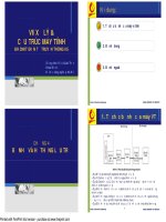
Basic computer architecture
4
Instruction set
An instruction is a string of bits grouped into a number of
different fields, such as
Instruction sets
Instruction types
Addressing modes
Instruction cycle
Processor design flow
A typical instruction, such as, a=b+c, where a, b, and c
are stored in memory at location A, B, and C can be
expressed in assembly language format,
Add A, B, C
or, register-transfer format
Mem[A] <- Mem[B]+ Mem[C]
5
Typical instructions
Register-to-register instructions
Add RA, RB, RC ( RF[A] RF [B]+ RF [C] )
Memory instructions ( load and store )
Load R2, A ( RF[2] MEM [A] )
Store A, R2 ( MEM[A] RF [2] )
Control instructions ( branch instruction )
Beq R2, R3, A
if R2=R3 then PC MEM[A]
if R2 !=R3 then PC PC+1
6
Number of address fields vs. performance
Mathematical expression: C = (a+b)(a-b)
Code with three-address instructions:
Add X, A, B ( Mem[X] Mem[A]+ Mem[B] )
Sub C, A, B ( Mem[C] Mem[A]- Mem[B] )
Mul C, X, C ( Mem[C] Mem[X] x Mem[C] )
Code size: 3 instructions
Code performance: 3 memory accesses for
instructions, 9 memory accesses for data
7
Number of address fields vs. performance
Mathematical expression: C = (a+b)(a-b)
Code with two-address instructions( with
temporary data in memory ):
Move X, A ( Mem[X] Mem[A] )
Add X, B ( Mem[X] Mem[X]+ Mem[B] )
Move C, A ( Mem[C] Mem[A] )
Sub C, B ( Mem[C] Mem[C]- Mem[B] )
Mul C, X ( Mem[C] Mem[C] x Mem[X] )
Code size: 5 instructions
Code performance: 5 memory accesses for
instructions, 10 memory accesses for data
8
Number of address fields vs. performance
Mathematical expression: C = (a+b)(a-b)
Code with one-address instructions( with temporary data
in the accumulator ):
Load A ( ACC Mem[A] )
Add B (ACC ACC]+ Mem[B] )
store X ( Mem[X] ACC )
Load A ( ACC Mem[A] )
Sub B ( ACC ACC- Mem[B] )
Mul X ( ACC ACC x Mem[X] )
store C ( Mem[C] ACC )
Code size: 7 instructions
Code performance: 7 memory accesses for instructions, 7
memory accesses for data
9
Number of address fields vs. performance
Mathematical expression: C = (a+b)(a-b)
Code with two-address instructions( with temporary data
in the register file ):
Load R1, A ( RF[1] Mem[A] )
Load R2, B ( RF[2] Mem[B] )
Move R3, R1 ( RF[3] RF[1] )
Add R1, R2 ( RF[1] RF[1]+ RF[2] )
Sub R3, R2 ( RF[3] RF[3]- RF[2] )
Mul R1, R3 ( RF[1] RF[1] x RF[3] )
Store C, R1 (Mem[C] RF[1] )
Code size: 7 instructions
Code performance: 7 memory accesses for instructions, 3
memory accesses for data
10
Number of address fields vs. performance
Code with three-address register instructions and
two-address memory instructions ( with
temporary data in the register file ):
Load R1, A ( RF[1] Mem[A] )
Load R2, B ( RF[2] Mem[B] )
Add R3, R1, R2 ( RF[3] RF[1]+ RF[2] )
Sub R4, R3, R2 ( RF[4] RF[3]- RF[2] )
Mul R5, R4, R3 ( RF[5] RF[3] x RF[4] )
store C, R5 ( Mem[C] RF[5] )
Code size: 6 instructions
Code performance: 6 memory accesses for
instructions, 3 memory accesses for data
11
Addressing modes
Implied
Immediate
Direct
Indirect
12
Addressing modes
Relative
Indexed
“1”
13
Bài tập
Viết các câu lệnh aseembly tính hàm số sau y = x2+2x+3,
khi biết giá trị x. Viết các câu lệnh đó
Lệnh 3 địa chỉ, lệnh thao tác truy xuất ô nhớ 2 địa chỉ
Lệnh 2 địa chỉ
Lệnh 1 địa chỉ
Cho 2 mảng mỗi mảng 100 phần tử, tính tổng của các
phần tử aixi , Dùng nhóm lệnh 2 địa chỉ (thanh ghi, bộ
nhớ), chế độ toán hạng:
Địa chỉ trực tiếp
Địa chỉ gián tiếp
14
Instruction cycle
IR = Instruction Register
PC = Program Counter
Memory stores all instructions and data
15
Processor design flow
16
Instruction-set design
Program size vs. processor size
Complex Instruction-set
powerful instructions -> shorter programs
powerful instructions -> complex datapath, control unit
complex instructions -> several clock cycles
complex datapath, control unit -> longer clock period
complex instructions -> poor pipeline
Reduced Instruction-set
simple instructions -> longer programs
simple instructions -> simple datapath, control unit
simple instructions -> single clock cycle
simple datapath -> shorter clock period
simple instructions -> excellent pipeline
17
Example
Design an instruction set of a 16-bit processor.
18
Complex instruction-set for a 16-bit processor
a) Register instructions:
arithmetic, logic,
move and shift
Op Dest, Src1, Src2
RF (Dest) RF(Src1) Op RF(Src2)
b) Memory instructions:
load and store
Name
L imm Dest
L dir Dest
L rel Dest , Src2
L in Dest
S dir Scr1
S rel Src1 , Src2
S in Src1
Name Action
RF [Dest] Address
RF [Dest] Mem[Address]
RF [Dest] Mem[RF[Src2]+Address]
RF [Dest] Mem[Address]
Mem [Address] RF[Src1]
Mem[RF [Src2]]+Address RF[Src1]
Mem [Mes[Address]] RF[Src1]
19
Complex instruction-set for a 16-bit processor
c) Control instructions:
jump, branch, call and
return
Name
Jump Address
Brel Address
Call Address, Src1
Return
d) Miscellaneous instructions:
no-op, clear, status, set and
reset
Name
No-op
Clear Dest
Lstat Src1, Src2
Sstat Dest
Rstat Dest
Action
PC Address
PC PC+1 if Status[rel] = 0
PC Address if Status[rel] = 1
Mem[Src1] PC+1; PC <- Address;
RF[Src1] RF[Src2]+1
PC Mem[Src1] ;
RF[Src1] RF[Src1]-1
Action
Do nothing
RF [Dest] 0
Status R[Src1] >=< RF[Src2]
status [Dest] 1
status [Dest] 0
20
CISC Design
Flowchart IS
A behavioral description of that processor.
Execute cycles of all instructions.
Not architectural detail.
Exist: memory, register file, program counter, instruction
register, a status register.
21
Instruction-set flowchart
22
Instruction-set flowchart
23
Component allocation for the 16-bit processor
Components: 64K x 16 Memory
8 x 6 Register file ALSU
Instruction register ( IR )
Program counter ( PC )
Address register ( AR )
Data register ( DR )
Status register ( Status )
Control unit
AR, DR needed to shorten clock period
24
Processor ASM chart (scheduled IS chart)
IR: thanh ghi lệnh
RF: register file
PC: program counter
AR: thanh ghi địa chỉ
DR: thanh ghi địa chỉ
Status: thanh ghi
trạng thái
25
Processor ASM chart (scheduled IS chart)