AN0877 devicenet™ group 2 slave firmware for PIC18 with CAN
Bạn đang xem bản rút gọn của tài liệu. Xem và tải ngay bản đầy đủ của tài liệu tại đây (327.52 KB, 34 trang )
AN877
DeviceNet™ Group 2 Slave Firmware for PIC18 with CAN
Author:
Ross Fosler
Microchip Technology Inc.
INTRODUCTION
Throughout this application note, there are references
to the specification. All references are to Volume I of
the specification unless otherwise noted.
FIGURE 1:
The DeviceNet™ system is an open network standard,
built on the Controller Area Network (CAN), designed
to reduce the cost and time to install industrial devices
while providing compatibility with multiple vendors. The
DeviceNet specification is available from the Open
DeviceNet Vendor Association, Inc. (ODVA). Example
DeviceNet devices might include motor starters,
valves, sensors, displays and more.
DeviceNet™
Protocol
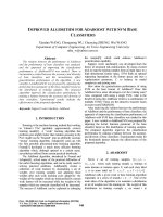
The DeviceNet specification covers multiple layers, from
the wiring and protection circuits, up to the software
protocol and application definition (see Figure 1);
however, this application note only focuses on a specific
development of the software known in the specification
as the Predefined Master/Slave Connection Set. To be
even more accurate, this application note only presents
a slave node within the Predefined Connection Set, also
referred to as a Group 2 Slave.
The Group 2 Slave developed here is designed with the
following features:
•
•
•
•
•
•
Supports Polling Messaging
Supports Multicast Polling Messaging
Supports Change of State/Cyclic Messaging
Supports Bit Strobe Messaging
Supports Acknowledged Fragmentation
Supports Unacknowledged Fragmentation
This application note, with attached firmware, is provided to accelerate the process to design a Group 2
Slave node but not do all of the work. There are many
details to a slave node that require an understanding of
the target application; therefore, this implementation is
provided in a very general form with numerous configurable parameters, event handling functions and variables that must be set or developed for the application.
Essentially, you cannot develop a DeviceNet application without some knowledge of the DeviceNet system
and its specification. It is a good idea to have the
complete specification available for reference while
designing a node.
The firmware associated with this document may
change as new features are added.
2003 Microchip Technology Inc.
LAYER PROTOCOL
Application Layer
CAN
Protocol
Data Link Layer
Physical
Layer
Physical Layer
Transmission
Media
Media Layer
OVERVIEW OF THE FIRMWARE
The DeviceNet system is described in the specification
as a collection of objects. Figure 2 shows a simplified
view of the object model. There are a number of possible objects within the object model but the required
objects include:
•
•
•
•
Connection Object
Message Router Object
Identity Object
DeviceNet Object
These are the objects that are developed in this
application note. Other objects not listed may become
available in future revisions of the firmware.
The Connection Object
The Connection Object manages all communications
between the CAN bus and higher level objects and
contains a number of source files. It can contain
multiple instances as defined by the Predefined
Master/Slave Connection Set (see Chapter 7 of the
specification). Table 1 lists the files associated with the
Connection Object.
DS00877A-page 1
AN877
The DeviceNet Object
The Identity Object
In this design, there is one instance of the DeviceNet
Object. It contains network related information about
the node, such as baud rate, MAC ID and more. It is
split into two source files as shown in Table 2; one file
contains lower level information, while the other is
application dependent and requires development
based on the requirements of the application.
The Identity Object contains information that identifies
the device, such as serial number and description. Like
the DeviceNet Object and the Connection Object, there
are some application specific dependencies that must
be developed for the Identity Object. Table 3 identifies
the files associated with the Identity Object.
The Router Object
The Router Object routes Explicit Messages to the
appropriate object. In this design, routes are static, plus
the object has no external visibility over the DeviceNet
system.
FIGURE 2:
SIMPLE OVERVIEW OF OBJECT CONNECTION
Identity
Object
Application Related
Objects
Me
gin
ssa
g
E
Me xpli
s s c it
ag
i ng
I/O
Message
Router
DeviceNet™
Object
Connection Object
CAN bus
DS00877A-page 2
2003 Microchip Technology Inc.
AN877
TABLE 1:
CONNECTION OBJECT RELATED FILES
File Name
Description
conn.c
This file contains several connection managing functions to capture communications events and
dispatch them to appropriate instances or other managing functions.
conn1.c
This file provides the Predefined Explicit Messaging connection functionality.
conn2.c
This file provides the Predefined Polled/Change of State/Cyclic I/O Messaging connection
functionality.
conn3.c
This file provides the Predefined Bit Strobed I/O Messaging connection functionality.
conn4.c
This file provides the Predefined Change of State/Cyclic I/O Messaging connection functionality.
conn5.c
This file provides the Predefined Multicast Polled I/O Messaging connection functionality.
conn6.c
This file provides the Unconnected Explicit Messaging functionality which looks similar to other
regular I/O connections, but does not support all the events and fragmentation.
conn7.c
This file provides the Duplicate MAC ID Messaging functionality which looks similar to other
regular I/O connections, but does not support all the events and fragmentation.
frag.c
This file contains the I/O Fragmentation managing functions.
CAN.C
This file contains the abstracted CAN driver routines. The functions are abstract to support the
possibility of having a variety of CAN options.
EMM.c
This file is referred to as the Explicit Messaging Manager. It contains functions to interface Explicit
Messaging to the router. Routing specific information is parsed and placed in the Router Object.
UEMM.c
This file is referred to as the Unconnected Explicit Messaging Manager. It contains functions to
interface Unconnected Explicit Messaging to the router. However, only the “Allocate” and “Release”
commands directed to the DeviceNet Object are allowed; all other messages are ignored.
NASM.c
This file contains the Network Access State Machine functions. These functions are bound
together with the Identity Object and the Duplicate MAC ID Message.
UsrConn.c
Application specific logic for the Connection Object is contained within this file; therefore, this file
must be developed for the application.
TABLE 2:
DeviceNet OBJECT RELATED FILES
File Name
Description
dnet.c
This file contains most of the required logic for the DeviceNet Object. It contains DeviceNet global
variables and Explicit Message handling for the commands identified in Section 5-5 of the
specification.
UsrDNet.c
Logic that depends on the application is contained within this file; therefore, this file must be
developed for the application.
TABLE 3:
IDENTITY OBJECT RELATED FILES
File Name
Description
ident.c
This file contains most of the required logic for the Identity Object. It contains global variables and
Explicit Message handling for the commands identified in Volume II, Section 6-2 of the
specification.
UsrIdent.c
Logic that depends on the application is contained within this file; therefore, this file must be
developed for the application.
TABLE 4:
ADDITIONAL HELPER FILES
File Name
Description
class.h
Defined classes of objects.
errors.h
Defined Explicit Messaging errors.
typedefs.h
Internal data types.
2003 Microchip Technology Inc.
DS00877A-page 3
AN877
THE CONNECTION OBJECT
Once instantiated, each instance manages the events
that it receives. In general, the events include:
The Connection Object, as shown in Figure 3, is the
largest and most complex object in the design. Within
the object, all data and error events must be managed
which explains the complexity.
All events are received by the managing functions
within the conn.c file through calls to the CAN driver.
The events are decoded and dispatched to the appropriate instance based on the availability of the connection. Note that an instance of a connection does not
exist until it is explicitly created (see Section 5-5 of the
specification). The only two messages that are received
without explicitly instantiating a connection are the
Unconnected Explicit Request Message and the
Duplicate MAC ID Check Message (see Section 7-2 of
the specification).
FIGURE 3:
• ConnxCreate – Creates the object
• ConnxClose – Closes the object
• ConnxTimerEvent – Handles connection
related timers
• ConnxRxEvent – Handles received data
• ConnxTxOpenEvent – Handles transmit
availability
• ConnxTxEvent – Notification when data has
been put on the bus
• ConnxExplicitEvent – Handles Explicit
Messaging requests
At the upper level of the Connection Object are additional managers which process the received data for
the instances. This includes Unconnected and Connected Explicit Message handling, Network Access
Control (see Chapter 6 of the specification) and the
application specific I/O.
THE CONNECTION OBJECT AND HIGHER MANAGEMENT OBJECTS
Explicit Message
Manager
(EMM.c)
Inst. 1
(conn1.c)
Inst. 2
(conn2.c)
Inst. 3
(conn3.c)
Abstract CAN
Driver Functions
(CAN.C)
DS00877A-page 4
Unconnected
Explicit Message
Manager
(UEMM.c)
User I/O
Interface
(UsrConn.c)
Inst. 4
(conn4.c)
Inst. 5
(conn5.c)
Network Access
Manager
(NASM.c)
Msg. 6
(conn6.c)
Msg. 7
(conn7.c)
Tx, Rx, Fragmentation,
and Time Managing
Functions
(conn.c, frag.c)
2003 Microchip Technology Inc.
AN877
Internal Connection Object Services
The Connection Object manages I/O connection data
movement to and from the user supplied buffer. It is up
to the application to decide how to handle the data
above the Connection Object.
There are up to four possible predefined instances that
are defined (see Chapter 7 of the specification):
•
•
•
•
Polled Messaging
Bit Strobed Messaging
Cyclic/Change of State Messaging
Multicast Polled Messaging
Some basic internal services are provided through the
Connection Object for the purpose of managing I/O data.
mConnReadRdy
Query the Connection Object to determine the status of the read buffer of the specified connection number. Returns true
if a message has been received and is waiting in the receive buffer. Valid numbers are 1 through 7; however, only
numbers 2 through 5 should be used since these are where the I/O connections reside.
Syntax
unsigned char mConnReadRdy (unsigned char hInstance)
Example
if (mConnReadRdy(2))
{
// Process application stuff
ApplicationProcess();
// Free the connection to accept more data
mConnRead(2);
}
mConnWriteRdy
Query the Connection Object to determine the status of the write buffer of the specified connection number. Returns
true if the buffer is open to accept new data from transmission. Valid numbers are 1 through 7; however, only numbers
2 through 5 should be used since these are where the I/O connections reside.
Syntax
unsigned char mConnWriteRdy (unsigned char hInstance)
Example
if (mConnWriteRdy(2))
{
// Process application stuff
ApplicationProcess();
// Release the connection to write the data
mConnWrite(2);
}
2003 Microchip Technology Inc.
DS00877A-page 5
AN877
mConnRead
Calling this function with the appropriate instance number will indicate to the Connection Object that all data has been
processed and the connection should be ready to receive more data.
Syntax
void mConnRead (unsigned char hInstance)
mConnWrite
Calling this function with the appropriate instance number will indicate to the Connection Object that all data has been
loaded into the connection’s buffer for transmitting on the bus.
Syntax
void mConnWrite (unsigned char hInstance)
DS00877A-page 6
2003 Microchip Technology Inc.
AN877
Connection Object Events
There are events and global registers that cannot be
defined without the application. For this reason, they
are passed up to the UsrConn.c object for application
specific processing. Code must be developed in this file
to manage appropriate events.
Upon instantiation, a “Create Event” is generated with
the appropriate instance number passed. This event
must be handled to set up some application dependent
attributes. The attributes that must be set up are:
•
•
•
•
•
•
•
•
Produced path
Consumed path
Produced path length
Consumed path length
Pointer to the consumed data
Pointer to the produced data
Length of the consumed data
Length of the produced data
Like the “Create Event”, there is also a “Close Event”
when the connection is closed. This is provided to notify
the application when the connection is no longer available.
Two other events that may or may not necessarily be
set up are the “Rx Event” and the “Tx Event”. These
events are generated when data has been transmitted
or received. These are provided for any application
specific event handling; however, they do not necessarily need to be handled as an event. Receive and
transmit can be polled through normal Connection
Object functions.
One other event is the “Set Attribute Event”. This event
must be handled for any attribute that is not entirely
dependent on the Connection Object alone. The
attributes are:
•
•
•
•
_ATTRIB_CLASS_TRIGGER
_ATTRIB_PRODUCED_CONN_PATH
_ATTRIB_CONSUMED_CONN_PATH
_ATTRIB_PRODUCED_CONN_SIZE
Not all attributes are required to be settable; however,
the event must be handled to generate an error if the
event occurs.
UsrConnCreateEvent
This event function is called when a connection is created by an allocate request. The instance number is passed indicating the source of the event. This event is an indication to the application to provide resources necessary for the connection to function. Other than application specific resources, buffer space and path information must be provided. If
resources are not available, then the application should return ‘0’ to this event; otherwise, the application should return
any other value to allow the creation of the connection.
Syntax
unsigned char UsrConnCreateEvent (unsigned char hInstance)
Example
unsigned char UsrConnCreateEvent(unsigned char hInstance)
{
switch (hInstance)
{
case 2:
// Set path information according to Appendix I
// of the DeviceNet specification
// Set the connection sizes
uConn2.attrib.consumed_con_size.word = 13;
uConn2.attrib.produced_con_size.word = 20;
// Set the pointers to the buffers
uConn2.rx.pMsg = uConn2RxBuffer;
uConn2.tx.pMsg = uConn2TxBuffer;
return(1);
case 3:
// Set path and connection information
return(1);
case 4:
// Set path and connection information
return(1);
case 5:
// Set path and connection information
return(1);
}
}
2003 Microchip Technology Inc.
DS00877A-page 7
AN877
UsrConnCloseEvent
This event function is called when a connection is closed by a time-out or release request. The instance number is
passed indicating the source of the event. This event is an indication to the application to release any allocated
resources.
Syntax
void UsrConnCloseEvent (unsigned char hInstance)
UsrConnRxDataEvent
This event function is called when a connection has received data. The instance number is passed indicating the source
of the event.
Syntax
void UsrConnRxDataEvent (unsigned char hInstance)
UsrConnTxDataEvent
This event function is called when a connection has transmitted its data. The instance number is passed indicating the
source of the event.
Syntax
void UsrConnTxDataEvent (unsigned char hInstance)
UsrConnSetAttribEvent
This event is generated when an attribute that is defined by the application has been requested to be changed by an
Explicit Message. The application must decode the attribute and generate an appropriate response to the request. Refer
to the Router Object for details on internal services to handle Explicit Message responses.
Syntax
void UserConnSet AttribEvent (unsigned char hInstance)
Example
switch (mRouteGetAttributeID())
{
case _ATTRIB_CLASS_TRIGGER:
// Process request to set this
break;
case _ATTRIB_PRODUCED_CONN_PATH:
// Process request to set this
break;
case _ATTRIB_CONSUMED_CONN_PATH:
// Process request to set this
break;
case _ATTRIB_PRODUCED_CONN_SIZE:
// Process request to set this
break;
}
DS00877A-page 8
attribute
attribute
attribute
attribute
2003 Microchip Technology Inc.
AN877
Connection Attributes
Connection attributes are common to all I/O connections. Depending on the connection, some of the
attributes may not be settable. Table 5 lists and identifies
the attributes.
TABLE 5:
COMMON VISIBLE CONNECTION ATTRIBUTES
Attribute
Definition
state
Indicates the state of the connection instance.
transportClass
Indicates the type of connection.
produced_cid
This attribute contains the produced connection ID.
consumed_cid
This attribute contains the consumed connection ID.
initial_comm_char
produced_con_size
This specifies the maximum size of the produced message for this connection.
consumed_con_size
This specifies the maximum size of the consumed message for this connection.
expected_packet_rate This specifies the minimum rate at which data is expected to be received for this
connection.
produced_path_len
Specifies the length of the produced path information.
produced_path
Specifies the produced path.
consumed_path_len
Specifies the length of the consumed path information.
consumed_path
Specifies the consumed path.
2003 Microchip Technology Inc.
DS00877A-page 9
AN877
THE DeviceNet OBJECT
Internal DeviceNet Object Services
The DeviceNet Object contains primarily device specific information; some of this information is application
specific and some does not depend on the application.
Thus, like other objects in this design, it is split. Most of
the decoding, general logic and global variables are
provided in dnet.c, while application dependent
functions and globals are available in UsrDNet.c.
In this section, several internal services are identified
and described which are available to manage the
DeviceNet Object and the device. These services should
be used by the application’s managing functions to indicate any hardware changes. For example, the application should use the functions mDNetSetMACSwChange
and mDNetSetBaudSwChange to indicate any changes
in the switches, if switches are installed in the device.
Note:
Many of the functions are purely macro
based, so extra code space is not used if
the function is not used in the application.
mDNetSetMACID
This function sets the MAC ID. Use this at initialization time.
Syntax
void mDNetSetMACID (USINT MACID)
mDNetSetSetBaudRate
This function sets the baud rate. Valid values are 0, 1 and 2. Use this at initialization time.
Syntax
void mDNetSetBaudRate (USINT BaudRate)
mDNetSetBOI
Set the bus off interrupt action. This should be asserted at initialization and can be asserted during normal operation
when handling a “Set Attribute Event”.
Syntax
void mDNetSetBOI (BOOL BOI)
mDNetSetMACSwChange
Set the MAC ID switch change indication if supported. The application should use this to notify the DeviceNet Object of
the change. Typically, if the application has switches, it should notify the DeviceNet firmware that the switch has
changed since last reset.
Syntax
void mDNetSetMACSwChange (BOOL SwitchChange)
mDNetSetBaudSwChange
Set the baud rate switch change indication if supported. The application should use this to notify the DeviceNet Object
of the change. Typically, if the application has switches, it should notify the DeviceNet firmware that the switch has
changed since last reset.
Syntax
void mDNetSetBaudSwChange (BOOL SwitchChange)
DS00877A-page 10
2003 Microchip Technology Inc.
AN877
mDNetSetMACSwValue
Set the MAC ID switch value if supported. The application should use this to notify the DeviceNet Object of the switch
value.
Syntax
void mDNetSetMACSwValue (USINT SwitchValue)
mDNetSetBaudSwValue
Set the baud rate switch value if supported. The application should use this to notify the DeviceNet Object of the switch
value.
Syntax
void mDNetSetBaudSwValue (USINT SwitchValue)
mDNetGetMACID
Get the current MAC ID value stored in the DeviceNet Object.
Syntax
USINT mDNetGetMACID ()
mDNetGetBaudRate
Get the current baud rate value stored in the DeviceNet Object.
Syntax
USINT mDNetGetBaudRate()
mDNetGetBOI
Get the current bus off interrupt value stored in the DeviceNet Object.
Syntax
BOOL mDNetGetBOI ()
mDNetGetBusOffCount
Get the current bus off count value stored in the DeviceNet Object. This value is updated by the Connection Object Error
Management function.
Syntax
USINT mDNetGetBusOffCount ()
mDNetGetAllocChoice
Get the current allocation choice byte. This value is changed based on the requests from the server and the internal
watchdog timers. This could be used internally to get an indication of what connection has been allocated.
Syntax
USINT mDNetGetAllocChoice ()
2003 Microchip Technology Inc.
DS00877A-page 11
AN877
mDNetGetMasterMACID
Get the current allocated Master MAC ID. Valid values are 0 to 63 and 255. A value of 255 indicates that no client has
allocated this node.
Syntax
USINT mDNetGetMasterMACID ()
mDNetMACSwChange
Get the stored MAC ID switch change value.
Syntax
void mDNetSetBOI (unsigned char MACID)
mDNetBaudSwChange
Get the stored baud rate switch change value.
Syntax
void mDNetSetBOI (unsigned char MACID)
mDNetGetMACSwValue
Get the stored MAC ID switch value.
Syntax
USINT mDNetGetMACSwValue ()
mDNetGetBaudSwValue
Get the stored baud rate switch value.
Syntax
USINT mDNetGetBaudSwValue ()
DS00877A-page 12
2003 Microchip Technology Inc.
AN877
DeviceNet Object Events
There are two events that must be handled by the application that occur in the DeviceNet Object, which are
listed below.
Within the UsrDNetInitEvent function, several
attributes specific to the DeviceNet Object must be set.
For example, the MAC ID and the baud rate can be
switch values, or internal values stored in memory,
depending on the application design. Thus, these initializations are left to the application designer. The same
situation applies to the UsrDNetSetAttribEvent
function. Refer to Section 5-5 of the specification for
information on the DeviceNet Object. The specification
identifies the settable attributes and the conditions that
enable the settable attributes.
UsrDNetInitEvent
This event occurs when the DeviceNet Object is initialized. A number of attributes must be set up.
Syntax
void UsrDNetInitEvent (void)
Example
void UsrDNetInitEvent(void)
{
mDNetSetMACID(12);
mDNetSetBaudRate(0);
mDNetSetBOI(0);
mDNetSetMACSwChange(0);
mDNetSetBaudSwChange(0);
mDNetSetMACSwValue(0);
mDNetSetBaudSwValue(0);
}
UsrDNetSetAttribEvent
The “Set Attribute Event” occurs when the setting of an attribute cannot be handled internally because of some
application dependency.
Syntax
void UsrDNetSetAttribEvent (void)
Example
void UsrDNetSetAttribEvent(void)
{
switch (mRouteGetAttributeID())
{
case _ATTRIB_MAC_ID:
// Application code to handle setting MAC ID
break;
case _ATTRIB_BAUD_RATE:
// Application code to handle setting baud rate
break;
case _ATTRIB_BOI:
// Application code to handle setting BOI
break;
}
}
2003 Microchip Technology Inc.
DS00877A-page 13
AN877
THE IDENTITY OBJECT
The Identity Object contains device identification information; some of this information is application specific
and some does not depend on the application. Thus,
like other objects in this design, it is split. Most of the
decoding, general logic and global variables are
provided in ident.c, while application dependent
functions and globals are available in UsrIdent.c.
Identity Object Events
UsrIdentityCommunicationFaultEvent
This event is generated when communications has faulted (i.e., the bus off count has exceeded 255). Refer to Chapter 6
of the DeviceNet specification.
Syntax
void UsrIdentityCommunicationFaultEvent(void)
UsrIdentityFaultEvent
This event occurs when the Network Access State Machine has been corrupted. If this ever occurs, a Reset is probably
necessary.
Syntax
void UsrIdentityFaultEvent(void)
UsrIdentityReset
This function is called when a Reset has been requested. This occurs through an Explicit Messaging request.
Syntax
void UsrIdentityReset(void)
Example
void UsrIdentityReset(void)
{
USINT resetData;
// Ignore the first byte (it is actually the attribute ID)
mRouteGetByte();
// Verify that one byte has been received
if (mRouteTestValidInputDataLen(1))
{
// Get the data (6-2.3.1)
resetData = mRouteGetByte();
if (resetData == 0)
{
// Perform a soft reset
}
else if (resetData == 1)
{
// Perform an ‘out of the box’ reset
}
}
}
DS00877A-page 14
2003 Microchip Technology Inc.
AN877
UsrIdentityInitEvent
This is the initialization event. The identity globals must be set up in this event.
Syntax
void UsrIdentityInitEvent(void)
Example
ROM unsigned char cProductName[] = {"Microchip Device"};
void UsrIdentityInitEvent(void)
{
mIdentitySetVendorID(12345);
mIdentitySetDeviceType(2);
mIdentitySetProductCode(3);
mIdentitySetMajorRevision(1);
mIdentitySetMinorRevision(0);
mIdentitySetStatus(0);
mIdentitySetSerial(28933892);
mIdentitySetNameP(cProductName);
mIdentitySetNameLen(sizeof(cProductName));
}
2003 Microchip Technology Inc.
DS00877A-page 15
AN877
Internal Identity Object Services
The following identifies and describes several internal
services that are available to manage the Identity
Object and the device. These services should be used
by the application’s managing functions to indicate any
changes related to the Identity Object, most notably the
status of the device. For example, the application
should use the function, mIdentitySetStatus, to
indicate any application level Fault conditions. See the
functions below.
mIdentitySetVendorID
Use this to set the vendor ID of the node. This number is assigned by ODVA.
Syntax
void mIdentitySetVendorID (UINT VendorID)
void mIdentitySetVendorIDL (USINT VendorID)
void mIdentitySetVendorIDH (USINT VendorID)
mIdentityGetVendorID
Use this to get the stored vendor ID.
Syntax
UINT mIdentityGetVendorID (void)
USINT mIdentityGetVendorIDL (void)
USINT mIdentityGetVendorIDH (void)
mIdentitySetDeviceType
Use this to set the device type.
Syntax
void mIdentitySetDeviceType (UINT DeviceType)
void mIdentitySetDeviceTypeL (USINT DeviceType)
void mIdentitySetDeviceTypeH (USINT DeviceType)
mIdentityGetDeviceType
Use this to get the device type.
Syntax
UINT mIdentityGetDeviceType (void)
USINT mIdentityGetDeviceTypeL (void)
USINT mIdentityGetDeviceTypeH (void)
mIdentitySetProductCode
Set the product code.
Syntax
void mIdentitySetProductCode (UINT ProductCode)
void mIdentitySetProductCodeL (USINT ProductCode)
void mIdentitySetProductCodeH (USINT ProductCode)
DS00877A-page 16
2003 Microchip Technology Inc.
AN877
mIdentityGetProductCode
Get the product code.
Syntax
UINT mIdentityGetProductCode (void)
USINT mIdentityGetProductCodeL (void)
USINT mIdentityGetProductCodeH (void)
mIdentitySetMajorRevision
Set the major revision.
Syntax
void mIdentitySetMajorRevision (USINT MajorRev)
mIdentityGetMajorRevision
Get the major revision.
Syntax
USINT mIdentityGetMajorRevision (void)
mIdentitySetMinorRevision
Set the minor revision.
Syntax
void mIdentitySetMinorRevision (USINT MinorRev)
mIdentityGetMinorRevision
Get the minor revision.
Syntax
USINT mIdentityGetMinorRevision (void)
mIdentitySetSerial
Set the serial number.
Syntax
void
void
void
void
void
mIdentitySetSerial (UDINT SerialNo)
mIdentitySetSerialL (USINT SerialNo)
mIdentitySetSerialH (USINT SerialNo)
mIdentitySetSerialUL (USINT SerialNo)
mIdentitySetSerialUH (USINT SerialNo)
2003 Microchip Technology Inc.
DS00877A-page 17
AN877
mIdentityGetSerial
Get the serial number.
Syntax
UDINT
USINT
USINT
USINT
USINT
mIdentityGetSerial (void)
mIdentityGetSerialL (void)
mIdentityGetSerialH (void)
mIdentityGetSerialUL (void)
mIdentityGetSerialUH (void)
mIdentitySetStatus
Set the status of the device. This must be set by the application to indicate the current status of the device (see
Section 6-2.2 of the specification).
Syntax
void mIdentitySetStatus (WORD DevStat)
void mIdentitySetStatusL (unsigned char DevStat)
void mIdentitySetStatusH (unsigned char DevStat)
mIdentityGetStatus
Get the status of the device.
Syntax
WORD mIdentityGetStatus (void)
unsigned char mIdentityGetStatusL (void)
unsigned char mIdentityGetStatusH (void)
mIdentitySetNameP
Set a ROM pointer to the name of the device.
Syntax
void mIdentitySetNameP (ROM unsigned char pName)
mIdentitySetNameLen
Set the length of the name.
Syntax
void mIdentitySetNameLen (unsigned char NameLen)
DS00877A-page 18
2003 Microchip Technology Inc.
AN877
THE ROUTER OBJECT
Although the Router Object has no external visibility
through Explicit Messaging, it has many internal
functions for routing Explicit Message data. These
functions are listed and described in the “Internal
Routing Services” section.
Handling Explicit Messaging
Every application object that has attributes and services has an Explicit Message handling function that
decodes the path information. The router automatically
parses the appropriate information and makes it available to the application. Plus, there are a number of
functions that are also available. All of the possible
functions are listed in the “Internal Routing Services”
section. Following are some of the more important
internal functions:
• mRoutePutByte – Put a byte into the response
buffer and automatically adjust some internal
pointers to the next byte in the buffer.
• mRouteGetByte – Read a byte from the receive
buffer and automatically adjust to the next byte in
the buffer.
• mRouteTestValidInputDataLen – Test the
length of the attribute data against the expected
data length.
• mRoutePutError – Set the appropriate error
response.
• mRouteGetServiceID – Get the service ID.
• mRouteGetInstanceID – Get the instance ID.
• mRouteGetAttributeID – Get the attribute ID.
• mRouteGetInBufferPtr – Get the pointer to
the buffer.
• mRouteGetInBufferDataLength – Get the
amount of data in the input buffer.
• mRouteGetOutBufferPtr – Get a pointer to
the output buffer.
• mRouteGetOutBufferLength – Get the
maximum length of the output buffer.
Refer to the source code for examples on handling
Explicit Messaging events.
Internal Routing Services
mRoutePutByte
Put a byte into the buffer to be transmitted by the Explicit Messaging connection. Internal pointers are maintained
automatically. Thus, multiple writes will write bytes sequentially in the buffer.
Syntax
void mRoutePutByte (USINT dataByte)
mRouteGetByte
Get a byte from the received Explicit Messaging connection buffer. Internal pointers are maintained automatically. Thus,
multiple reads will read bytes sequentially from the buffer.
Syntax
USINT mRouteGetByte (void)
mRouteTestValidInputDataLen
Verify the length of the input data. An error response is automatically generated if the boundary conditions are not met.
Syntax
unsigned char mRouteTestValidInputDataLen (unsigned char len)
2003 Microchip Technology Inc.
DS00877A-page 19
AN877
mRouteTestNonValidInputDataLen
Verify the length of the input data. An error response is automatically generated if the boundary conditions are not met.
Syntax
unsigned char mRouteTestNonValidInputDataLen (unsigned char len)
mRoutePutError
Put an error response in the buffer. Refer to errors.h and the specification for a list of known errors.
Syntax
void mRoutePutError (USINT errorCode)
mRouteRxLen
Get the receive data length.
Syntax
USINT mRouteRxLen (void)
mRouteTxLen
Get the transmit data length.
Syntax
USINT mRouteTxLen (void)
mRouteGetHeader
Get the header of the received Explicit Message.
Syntax
USINT mRouteGetHeader (void)
mRouteGetServiceID
Get the service ID of the received Explicit Message.
Syntax
USINT mRouteGetServiceID (void)
mRouteGetClassID
Get the class ID of the received Explicit Message.
Syntax
USINT mRouteGetClassID (void)
UINT mRouteGetClassID (void)
DS00877A-page 20
2003 Microchip Technology Inc.
AN877
mRouteGetInstanceID
Get the instance ID of the received Explicit Message.
Syntax
USINT mRouteGetInstanceID (void)
UINT mRouteGetInstanceID (void)
mRouteGetAttributeID
Get the attribute ID of the received Explicit Message.
Syntax
USINT mRouteGetAttributeID (void)
mRouteGetInBufferPtr
Get the pointer to the input buffer.
Syntax
USINT * mRouteGetInBufferPtr (void)
mRouteGetOutBufferPtr
Get the pointer to the output buffer.
Syntax
USINT * mRouteGetOutBufferPtr (void)
mRouteGetInBufferLength
Get the length of the input buffer.
Syntax
USINT mRouteGetInBufferLength (void)
mRouteGetInBufferDataLength
Get the length of data in the input buffer.
Syntax
USINT mRouteGetInBufferDataLength (void)
mRouteGetOutBufferLength
Get the length of the output buffer.
Syntax
USINT mRouteGetOutBufferLength (void)
mRouteGetOutBufferDataLength
Get the length of the data in the output buffer.
Syntax
USINT mRouteGetOutBufferDataLength (void)
2003 Microchip Technology Inc.
DS00877A-page 21
AN877
mRoutePutServiceID
Set the service ID. Typically this is used only when changing the Explicit Message response to an error response.
Syntax
void mRoutePutServiceID (USINT ServiceID)
mRoutePutInBufferPtr
Set the input buffer pointer.
Syntax
void mRoutePutInBufferPtr (USINT * pInBuf)
mRoutePutOutBufferPtr
Set the output buffer pointer.
Syntax
void mRoutePutOutBufferPtr (USINT * pOutBuf)
mRoutePutInBufferLength
Set the input buffer length.
Syntax
void mRoutePutInBufferLength (USINT length)
mRoutePutInBufferDataLength
Set the length of the data in the input buffer.
Syntax
void mRoutePutInBufferDataLength (USINT length)
mRoutePutOutBufferLength
Set the output buffer length.
Syntax
void mRoutePutOutBufferLength (USINT length)
mRoutePutOutBufferDataLength
Set the length of data in the output buffer.
Syntax
void mRoutePutOutBufferDataLength (USINT length)
DS00877A-page 22
2003 Microchip Technology Inc.
AN877
SUPPORTING FUNCTIONS
Setting Up a Timer
All of the managing and initialization functionality is
combined into a single source object. The primary
function is to manage communication, errors, time and
initialization while providing a simple interface. In this
case, there are three functions listed and described
below. These functions should be called by the
application’s main program.
The GoDNetProcessAllTickEvents function must
be called at the rate specified by the
TICK_RESOLUTION compile time option. The source
of the timing event can be determined by the
application. Refer to the source code for an example.
GoDNetProcessAllMsgEvents
This function processes all message and error management functions, essentially generating communications related
events. It should be called as often as possible to avoid missing events from the CAN driver.
Syntax
void GoDNetProcessAllMsgEvents (void)
Example
See example for the GoDNetInitializeAll function below.
GoDNetProcessAllTickEvents
This function combines all time related management into a single function. This function should be called based on an
application generated timing event. A timer or some external trigger could be used to do this.
Syntax
void GoDNetProcessAllTickEvents (void)
Example
See example for the GoDNetInitializeAll function below.
GoDNetInitializeAll
This function should be called at least one time. It generates all the initialization events, external and internal, to set up
the node for the DeviceNet system.
Syntax
void GoDNetInitializeAll (void)
Example
void main(void)
{
// Init the timer
TimerInit();
// Init all appropriate DeviceNet parameters
GoDNetInitializeAll();
while (1)
{
// Process all DeviceNet Messaging events
GoDNetProcessAllMsgEvents();
// Process all DeviceNet timer events
if (TimerIsOverflowEvent())
GoDNetProcessAllTickEvents();
// Process any application firmware
}
}
2003 Microchip Technology Inc.
DS00877A-page 23
AN877
COMPILE TIME SETUP
There are several compile time options that must be set
to configure the DeviceNet firmware. They are listed
and described in Table 6.
TABLE 6:
COMPILE TIME OPTIONS
Option
Definition
B125k_BRG1_SJW
B125k_BRG1_PRESCALE
B125k_BRG2_SEG2PHTS
B125k_BRG3_WAKFIL
B125k_BRG2_SEG1PH
Set the BRG values to achieve 125k for the desired clock frequency. Refer to
the PIC18FXX8 device data sheet (DS41159) for information on the CAN
module.
B125k_BRG3_SEG2PH
B125k_BRG2_PRSEG
B125k_BRG2_SAM
B250k_BRG1_SJW
B250k_BRG1_PRESCALE
B250k_BRG2_SEG2PHTS
B250k_BRG3_WAKFIL
B250k_BRG2_SEG1PH
Set the BRG values to achieve 250k for the desired clock frequency. Refer to
the PIC18FXX8 device data sheet (DS41159) for information on the CAN
module.
B250k_BRG3_SEG2PH
B250k_BRG2_PRSEG
B250k_BRG2_SAM
B500k_BRG1_SJW
B500k_BRG1_PRESCALE
B500k_BRG2_SEG2PHTS
B500k_BRG3_WAKFIL
B500k_BRG2_SEG1PH
Set the BRG values to achieve 500k for the desired clock frequency. Refer to
the PIC18FXX8 device data sheet (DS41159) for information on the CAN
module.
B500k_BRG3_SEG2PH
B500k_BRG2_PRSEG
B500k_BRG2_SAM
CLASS_WIDTH_16BIT
If this parameter is true, then the Router Object will assume 16-bit class ID for
all connected Explicit Messages; otherwise, 8-bit is default.
INSTANCE_WIDTH_16BIT
If this parameter is true, then the Router Object will assume 16-bit instance ID
for all connected Explicit Messages; otherwise, 8-bit is default.
TICK_RESOLUTION
Set the tick resolution that will be supplied to the firmware. The resolution must
be 1, 2, 4, 8, 16 or 32 ms.
SUPPORT_POLLED
Enable support for Polled I/O Messaging.
SUPPORT_BIT_STROBED
Enable support for Bit Strobed I/O Messaging.
SUPPORT_MULTICAST_POLL
Enable support for Multicast Polled I/O Messaging.
SUPPORT_COS
Enable support for COS I/O Messaging.
SUPPORT_CYCLIC
Enable support for Cyclic I/O Messaging.
SUPPORT_COS_BOTH_DIR
Enable support for COS/Cyclic I/O Messaging for both directions.
FRAGMENTATION_UNACK
Enable fragmentation support for I/O Messages.
FRAGMENTATION_ACK
Enable fragmentation support for Explicit Messages.
EXPLICIT_ACK_TIMER
Acknowledge time-out for fragmented transmission.
CONN_EXPLICIT_RX_SIZE
Set the receive buffer size for Explicit Messages.
DS00877A-page 24
2003 Microchip Technology Inc.
AN877
TABLE 6:
COMPILE TIME OPTIONS (CONTINUED)
Option
Definition
CONN_EXPLICIT_TX_SIZE
Set the transmit buffer size for Explicit Messages.
CONN_POLLED_RX_FRAG
Allow fragmentation for Receive Polled Messages.
CONN_POLLED_TX_FRAG
Allow fragmentation for Transmit Polled Messages.
CONN_MULTICAST_RX_FRAG
Allow fragmentation for Receive Multicast Polled Messages.
CONN_MULTICAST_TX_FRAG
Allow fragmentation for Transmit Multicast Polled Messages.
CONN_COS_CYCLIC_RX_FRAG
Allow fragmentation for Receive COS/Cyclic Messages.
CONN_COS_CYCLIC_TX_FRAG
Allow fragmentation for Transmit COS/Cyclic Messages.
ALLOW_MAC_ID
ALLOW_BAUD_RATE
ALLOW_BOI
ALLOW_BUS_OFF_COUNT
ALLOW_ATTRIB_ALLOC_INFO
Enable visibility of these parameters within the DeviceNet Object.
ALLOW_MAC_ID_SW_CH
ALLOW_BAUD_RATE_SW_CH
ALLOW_MAC_ID_SW_VAL
ALLOW_BAUD_RATE_SW_VAL
SETTABLE_BUS_OFF_COUNT
SETTABLE_BOI
SETTABLE_BAUD_RATE
Enable settability of these parameters within the DeviceNet Object.
SETTABLE_MAC_ID
CLASS_USER_DEFINED_1
CLASS_USER_DEFINED_1_NAME
CLASS_USER_DEFINED_2
CLASS_USER_DEFINED_2_NAME
CLASS_USER_DEFINED_3
CLASS_USER_DEFINED_3_NAME
CLASS_USER_DEFINED_4
CLASS_USER_DEFINED_4_NAME
CLASS_USER_DEFINED_5
CLASS_USER_DEFINED_5_NAME
These options set the application specific Explicit Messaging information for
the Router Object. The first parameter is the class ID and the second is the
name of the Explicit Message handling function. A class ID of ‘0’ is considered
non-existent.
CLASS_USER_DEFINED_6
CLASS_USER_DEFINED_6_NAME
CLASS_USER_DEFINED_7
CLASS_USER_DEFINED_7_NAME
CLASS_USER_DEFINED_8
CLASS_USER_DEFINED_8_NAME
2003 Microchip Technology Inc.
DS00877A-page 25