AN0531 intelligent remote positioner (motor control)
Bạn đang xem bản rút gọn của tài liệu. Xem và tải ngay bản đầy đủ của tài liệu tại đây (206.82 KB, 16 trang )
AN531
Intelligent Remote Positioner (Motor Control)
Author:
Steven Frank
Vesta Technology Inc.
INTRODUCTION
The excellent cost/performance ratio of the PIC16C5X
makes it well suited as a low-cost proportional D.C.
actuator controller. This application note depicts a
design for a remote intelligent positioning system using
a D.C. motor (up to 1/3 hp) run from 12V to 24V. The
position accuracy is one in eight bits or 0.4%. The
PIC16C5X receives its command and control information via a Microwire serial bus. However, any serial
communication method is applicable.
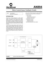
IMPLEMENTATION
The PIC16C5X based controller receives movement
commands from a host, compares them to the actual
position, calculates the desired motor drive level and
then pulses a full H-bridge (Figure 2). In this way it
serves as a remote intelligent positioner, driving the
load until it has reached the commanded position. It
can be used to control any proportional D.C. actuator
(i.e., D.C. motor or proportional valve).
This system is ideally suited for remotely positioned
valves and machinery. It can be used with D.C. motors
to easily automate manual equipment. Because of the
5-wire serial interface, the positioner can be installed
near its power supply and load. The remote intelligent
positioner can then be linked to the central control
processor by a small diameter easily routed cable.
Since the positioner is running its own closed-loop PID
algorithm (Figure 3), the host central processor needs
only to send position commands and is therefore free to
service the user interface, main application software
and command multiple remote positioners.
The limit switch inputs provide a safety net which keeps
the system from destroying itself in the event that the
feedback device is damaged. The optional current
sense input can be used to determine if the load has
jammed and prevent overheating of the actuator and
drive electronics.
The commanded positions are presented to the
PIC16C5X via a microwire type protocol at bit-rates of
up to 50 Kbs for a 4 MHz part. As currently
implemented in this application note, the position
request is the only communication. There are several
variable locations available which could be used to
down-load the loop gain parameters, read positioner
information, or set a current limit. The host that is sending the position request must set the chip select low,
and wait for the PIC16C5X to raise the "busy" (DO) line
high. At this point, eight data bits can be clocked into
the PIC16C5X. The requested position is sent most significant bit first and can be any 8-bit value. Values 1
through 255 represent valid positions with 0 being
reserved for drive disable.
The PIC16C5X acquires its data by way of a
Microwire A/D converter. This part was chosen for low
cost while providing adequate performance. In Figure 1
the second channel of the A/D converter is shown connected to a peak current detector. If the user desires,
the PIC16C5X could monitor and protect the motor
from overcurrent conditions by monitoring the second
channel.
FIGURE 1:
BLOCK DIAGRAM
TEST SET-UP
Microwire
Input
A/D
Converter
PIC16C5X
+5
Load
Pot
Power FET
Bridge
Position
M
P
P
N
N
Peak
Detector
Peak current
through motor
Microwire is a registered trademark of National Semiconductor Corporation.
1997 Microchip Technology Inc.
DS00531E-page 1
AN531
The H-bridge power amplifier will deliver 10 or more
amps at upto 24V when properly heat-sinked. It is wired
for a modified 4-quadrant mode of operation. One leg of
the bridge is used to control direction and the other leg
pulses the low FET and the high FET alternately to generate the desired duty-cycle. In this way the system will
operate well to produce a desired "speed" without the
use of a separate speed control loop. This allows use of
the PIC16C5X to control the PID algorithm for position
directly while having reasonable speed control. The
capacitance at the gates of the FETs combined with the
impedance of the drive circuits provides for turn-off of
the upper FET before the lower FET turns on... an
important criteria.
The three terms (proportional, integral, differential) are
summed algebraically and scaled to produce a percentage speed request between 0 and 100%. The sign of
the sum is used to control the direction of the H-bridge.
The loop calculations run approximately 20 times per
second on a 4 MHz part. This yields sufficient
gain-bandwidth for most positioning applications. If
higher system performance is desired, the number of
pulses can be reduced to 20 and a 16 MHz PIC16C5X
can be used. Your loop gains (KP, KI, KD) will have to be
recalculated, but the system sample rate will be
increased to 400 Hz. This should be sufficient to control
a system that has a response time of 20 milliseconds or
more.
The PID algorithm itself is where most of the meat of
this application note is located so let's look at it more
closely. The algorithm is formed by summing the
contribution of three basic components. The first
calculation is the error upon which the other terms are
based.
The key to using the PIC16C5X series parts for PID
control and PWM generation is to separate the two into
separate tasks. There simply is not the hardware
support or the processing speed to accurately do both
concurrently. It is fortunate therefore that it is not
necessary to do both concurrently. Most systems can
be stabilized with a much lower information update rate
than the PWM frequency. This supports the approach
of calculating the desired percentage, outputting the
PWM for a period of time and then recalculating the
new desired percentage. Using this technique, the inexpensive PIC16C5X can implement PID control, PWM
generation, and will still have processing time left over
for monitor or communication functions.
The error is the requested position minus the actual
position. It is a signed number whose magnitude can be
255. In order not to lose resolution, the error is stored
as an 8-bit magnitude with the sign stored separately in
the FLAGS register under ER_SGN. This allows us to
resolve a full signed 8-bit error with 8-bit math.
The proportional term is merely the algebraic difference of the requested position minus the actual position. It is scaled by a gain term (KP) called the
"proportional gain". The sign (+,-) of this term is important for it tells the system which direction it must drive
to correct the error. The proportional term is limited to
±100. Increasing the proportional gain term will improve
the dynamic and static accuracy of the system. Increasing it too much will cause oscillations.
The next term that gets calculated is the integral term
(KI). This term is traditionally formed by integrating the
error over time. In this application it is done by integrating the KI term over time. When the error is zero, no
integration is performed. This is a more practical way to
handle a potentially large number in 8-bit math. By
increasing the KI term the D.C. or static gain of the system is improved. Increasing the integral gain too much
can lead to low frequency oscillations.
About the Author:
Steven Frank has been designing analog and digital
control systems for ten years. His background is in
medical and consumer electronics. He has received
numerous patents in control systems and
instrumentation. At Vesta Technology Inc., Mr. Frank
works with a number of engineers on custom embedded control systems designs. Vesta Technology Inc. is
a provider of embedded control systems from an array
of standard products and designs. Vesta offers custom
design services and handles projects from concept to
manufacturing.
The differential term (KD) is a stabilizing term that
helps keep the integral and proportional terms from
overdriving the system through the desired position and
thus creating oscillations. As you use more proportional
and integral gain you will need more differential gain as
well. The differential gain is calculated by looking at the
rate of change of the positional error with respect to
time. It is actually formed as "delta error/delta time" with
the delta time being a program cycle.
DS00531E-page 2
1997 Microchip Technology Inc.
AN531
FIGURE 2:
PROGRAM
FLOWCHART
FIGURE 3:
PID ALGORITHM
FLOWCHART
Start
Start
Limit Switches Set?
Yes
ERR = POSR - POSA
ERR = POSR - POSA
No
New Position
Requested?
No
KPERR ← Min. of
←or
Min.
of
[KPKperr
• ERR
100]
[Kp • ERR or 100]
Yes
Get New Position
= POSR
SUM ← SUM + KPERR
SUM ← SUM + Kperr
ERR = Positive
ERR = Positive
Get Actual Position
= POSA
Yes
ACCM = ACCM + KI
ACCM
= ACCM
Direction
= CW+ KI
Direction = CW
No
Determine PID term
= PENT and direction
Fig. 3
SUM ← SUM + Min. of
SUM
← SUM
+ Min. of
[ACCM
or 100]
[ACCM or 100]
Set CNT = 100
PCH ← PCNT;
PCL ← 100 - PCNT
de/dt = ERR - OLD_ERR
de/dt = ERR - OLD_ERR
KDERR = KD • de/dt
Kderr = KD • de/dt
Drive Motor Hi;
PCH ← PCH - 1
PCH = 0?
ACCM = ACCM - KI
ACCM = ACCM
Direction
= CCW- KI
Direction = CCW
No
SUM ← SUM + Min. of
SUM
← SUM
+ Min. of
[KDERR
or 100]
[Kderr or 100]
Yes
Yes
SUM Positive
SUM Positive
Drive Motor Lo;
PCL ← PCL - 1
PCH = 0?
Set Bridge
Set
Bridge
for CW
for CW
No
No
Yes
Set Bridge
SetCCW
Bridge
for
for CW
PCNT = Min. of
PCNTor= 100]
Min. of
[SUM
[SUM or 100]
CNT ← CNT - 1
No
CNT = 0?
End
End
Yes
1997 Microchip Technology Inc.
DS00531E-page 3
AN531
FIGURE 4:
SCHEMATIC
Microwire
Port
+5
5
4
U1
1 RA2
2 RA3
RA1
RA0
3 T0CKI OSC1
4 MCLR OSC2
5 Vss
VDD
RB7
6 RB0
RB6
7 RB1
RB5
8 RB2
RB4
9 RB3
3
2
1
18
17
0.1 µF 10 µF
16
15
20 pF 20 pF U2
14
13
12
11
10
1
CS
5
DI
6 DO
PIC16C56
+PWR
1N4001
8
Vcc
3
CH1
2
CH0
7 CLK
4
GND
Position
Feedback
ADC0832
+5
+5
100
+PWR
1N4750
10 µF
35V P
Vi
U3
GND
Vo
10k x 3
0.1 µF
Input
Switches
LM7805
RTN
+PWR
0.1 x 3
P
+PWR
1k
1k
1000 µF
+PWR
35V
MTP23PO6
P
10k
1k
1k
+PWR
+PWR
10k
1k
Motor
1k
10k
1k
0.01 µF
1k
P 1k
1k P
1k
0.01 µF
10k
1k
MTP25NO5E
P
P
5
P
LM358
6 U4B
1N914
0.04
5 watt
7
P
1N914
+5
0.01 µF
3
2
8
U4A
1
P
LM358
Note 1: All pnp transistors are 2N3906.
2: All npn transistors are 2N3904.
3: All diodes 1N914 unless otherwise specified.
4: All zeners are 1N4742.
DS00531E-page 4
1k
47k
1 µF
4
1997 Microchip Technology Inc.
AN531
Please check the Microchip BBS for the latest version of the source code. Microchip’s Worldwide Web Address:
www.microchip.com; Bulletin Board Support: MCHIPBBS using CompuServe® (CompuServe membership not
required).
APPENDIX A: MWPOS.ASM
MPASM 01.40 Released
LOC OBJECT CODE
VALUE
00000000
00000019
00000003
00000001
00000000
00000003
00000004
00000005
00000006
00000007
00000008
00000009
0000000A
0000000B
0000000C
0000000D
0000000E
0000000F
00000010
00000011
00000012
00000013
00000013
00000014
00000014
00000015
00000015
00000016
00000016
00000017
00000018
00000000
00000001
00000000
00000002
00000001
00000000
MWPOS.ASM
1-16-1997
13:16:02
PAGE
1
LINE SOURCE TEXT
00001
00002
00003
00004
00005
00006
00007
00008
00009
00010
00011
00012
00013
00014
00015
00016
00017
00018
00019
00020
00021
00022
00023
00024
00025
00026
00027
00028
00029
00030
00031
00032
00033
00034
00035
00036
00037
00038
00039
00040
00041
00042
00043
00044
00045
00046
00047
00048
00049
00050
00051
00052
00053
00054
00055
00056
00057
00058
00059
00060
00061
00062
00063
00064
00065
00066
00067
00068
00069
00070
TITLE “ MicroWire Positioner “
;
;
;
mw8pos.asm
LIST P=16C56
;
;***************************************************************
;
;
Program:
MWPOS.ASM
;
Revision Date:
1/10/92 srf
REV. A
;
1-13-97
Compatibility with MPASMWIN 1.40
;
;******************************************************************************
;
;REGISTER EQUATES
;
PNTR
EQU
00H
; CONTENTS OF POINTER
FLAGS
EQU
19H
; USE THIS VARIABLE LOCATION AS FLAGS
; 0 BIT IS SIGN OF ERROR 1 IS NEGATIVE
; 1 BIT IS SIGN OF ERROR ACCUMULATOR
; 2 BIT IS SIGN OF THE DE/DT TERM
; 3 BIT IS DIRECTION 0 IS CW
; 4 BIT IS SIGN OF THE OLD ERROR
STATUS EQU
03H
F
EQU
1
W
EQU
0
SWR
EQU
03H
; STATUS WORD REGISTER
; 0 = CARRY
; 1 = DC
; 2 = Z, SET IF RESULT IS ZERO
FSR
EQU
04H
; FILE SELECT REGISTER
PORTA
EQU
05H
; I/O REG (A0-A3), (A4-A7 DEF=0)
PORTB
EQU
06H
; I/O REGISTER(B0-B7)
HI
EQU
07H
; NUMBER OF HIGH MICROSECONDS
LO
EQU
08H
; NUMBER OF LOW MICROSECONDS
PCNT
EQU
09H
; PERCENT DUTYCYCLE REQUEST
HI_T
EQU
0AH
; COUNTER FOR USECONDS LEFT/PULSE HI
LO_T
EQU
0BH
; COUNTER FOR USECONDS LEFT/PULSE LO
ERR1
EQU
0CH
; HOLDER FOR THE POSITIONAL ERROR
; THIS IS AN 8 BIT MAGNITUDE WITH THE SIGN
; KEPT IN THE FLAG REGISTER (9BIT SIGNED)
SUMLO
EQU
0DH
; PROGRESSIVE SUM OF THE PID TERMS
ACCUM
EQU
0EH
; ERROR ACCUMULATOR
ERR_O
EQU
0FH
; ERROR HISTORY USED FOR de/dt
; THIS IS AN 8 BIT MAGNITUDE WITH THE SIGN
; KEPT IN THE FLAG REGISTER (9BIT SIGNED)
POSR
EQU
10H
; POSITIONAL REQUEST
POSA
EQU
11H
; ACTUAL POSITION
CYCLES EQU
12H
; COUNTER FOR CYCLES OUT
mulcnd
ACCaLO
mulplr
ACCbLO
H_byte
ACCaHI
L_byte
ACCbHI
count
SUMHI
equ
EQU
equ
EQU
equ
EQU
equ
EQU
equ
EQU
13H
13H
14H
14H
15H
15H
16H
16H
17H
18H
;
;
;
;
;
;
;
;
;
;
8 bit multiplicand
same location used for the add
8 bit multiplier
same location used for the add
High byte of the 16 bit result
same location used for the add
Low byte of the 16 bit result
same location used for the add
loop counter
HIGH BYTE OF THE LOOP SUM
routine
routine
routine
routine
; PORT ASSIGNMENTS AND CONSTANTS
PWMCW
PWMCCW
CARRY
Z
Same
ER_SGN
1997 Microchip Technology Inc.
EQU
EQU
EQU
EQU
equ
EQU
0
1
0
2
1
0
;
;
;
;
;
;
CLOCKWISE PWM OUTPUT BIT
COUNTERCLOCKWISE PWM OUTPUT BIT
CARRY BIT IN THE STATUS REGISTER
THE ZERO BIT OF THE STATUS REGISTER
SIGN BIT FOR THE ERROR IN FLAG REGISTER
DS00531E-page 5
AN531
00000001
00000002
00000004
00000030
00000002
00000020
00000003
00000007
00000006
00000005
00000002
00000001
00000000
00000003
0000 0B88
0001
0002
0003
0004
0005
0006
0007
0008
0009
000A
000B
000C
000D
000E
0075
0076
0C08
0037
0213
0403
0334
0603
01F5
0335
0336
02F7
0A07
0800
000F 0917
0010
0011
0012
0013
0014
0015
0016
0017
0018
0019
001A
001B
001C
0213
01F4
0603
02B6
0215
01F6
0800
0273
02B3
0643
00F5
0275
0800
DS00531E-page 6
00071
00072
00073
00074
00075
00076
00077
00078
00079
00080
00081
00082
00083
00084
00085
00086
00087
00088
00089
00090
00091
00092
00093
00094
00095
00096
00097
00098
00099
00100
00101
00102
00103
00104
00105
00106
00107
00108
00109
00110
00111
00112
00113
00114
00115
00116
00117
00118
00119
00120
00121
00122
00123
00124
00125
00126
00127
00128
00129
00130
00131
00132
00133
00134
00135
00136
00137
00138
00139
00140
00141
00142
00143
00144
00145
00146
00147
00148
00149
00150
00151
00152
00153
AC_SGN
DE_SGN
OER_SGN
KP
KI
KD
DIR
CSN
BV
CK
MWDO
MWDI
MWCS
MWCK
EQU
EQU
EQU
EQU
EQU
EQU
EQU
EQU
EQU
EQU
EQU
EQU
EQU
EQU
1
2
4
30
2
20
3
7
6
5
2
1
0
3
;
;
;
;
;
;
;
;
;
;
;
;
;
;
SIGN BIT FOR THE ERROR ACCUMULATOR
SIGN BIT FOR DE/DT
SIGN BIT FOR THE OLD ERROR
PROPORTIONAL GAIN
INTEGRAL GAIN
DIFFERENTIAL GAIN
THE DIRECTION FLAG
CHIP SELECT NOT ON A/D
DATA LINE FOR THE A/D
CLOCK LINE FOR THE A/D
MICROWIRE DATA OUT FROM POSITIONER
MICROWIRE DATA IN TO POSITIONER
MICROWIRE CHIP SELECT TO POSITIONER
MICROWIRE CLOCK IN TO POSITIONER
;***** MACROS **********************************************
;
CLKUP
MACRO
; clock up macro for the microwire
BSF
PORTB,CK
; data acquisition from the a/d
NOP
ENDM
CLKDN
MACRO
BCF
NOP
ENDM
GET_BIT MACRO
BCF
BSF
BTFSC
BSF
RLF
BCF
NOP
ENDM
GOTO
PORTB,CK
; clock down macro for the microwire
; data acquisition from the a/d
; ** FOR RECEIVING A/D DATA **
SWR,CARRY
PORTB,CK
PORTB,BV
SWR,CARRY
POSA, F
PORTB,CK
;
;
;
;
;
;
SET CLOCK BIT HIGH
LOOK AT DATA COMING IN
SET THE CARRY FOR A 1
ROTATE THE W REG LEFT
SET THE CLOCK LOW
DELAY
CLRREG
;***** MATH ROUTINES ****************************************
;
; **** 8 BIT MULTIPLY ********
; *****************************
Begin Multiplier Routine
mpy_S
clrf
H_byte
clrf
L_byte
movlw
8
movwf
count
movf
mulcnd,W
bcf
STATUS,CARRY
; Clear the carry bit in the status Reg.
loop
rrf
mulplr, F
btfsc
STATUS,CARRY
addwf
H_byte,Same
rrf
H_byte,Same
rrf
L_byte,Same
decfsz count, F
goto
loop
retlw
0
; ******************************
; DOUBLE PRECISION ADD AND SUBTRACT ( ACCb-ACCa->ACCb )
D_sub
call
neg_A
; At first negate ACCa, then add
;****************
; Double Precision Addition ( ACCb+ACCa->ACCb )
D_add
;
;
neg_A
movf
addwf
btfsc
incf
movf
addwf
retlw
ACCaLO,W
ACCbLO, F
STATUS,CARRY
ACCbHI, F
ACCaHI,W
ACCbHI, F
00
comf
incf
btfsc
decf
comf
retlw
ACCaLO, F
ACCaLO, F
STATUS,Z
ACCaHI, F
ACCaHI, F
00
; add lsb
; add in carry
; add msb
; negate ACCa
1997 Microchip Technology Inc.
AN531
001D
001D
001E
001F
0020
0021
0022
0403
0336
0403
0335
0603
05F6
0023
0024
0025
0026
0027
0028
0403
0336
0403
0335
0603
05F6
0029
002A
002B
002C
002D
002E
0403
0336
0403
0335
0603
05F6
002F
0030
0031
0032
0033
0034
0403
0336
0403
0335
0603
05F6
0035
0035
0036
0037
0038
0039
003A
003B
003C
003C
003D
003E
003F
0040
0041
0042
0042
0043
0043
0044
0045
0046
0047
0048
0049
004A
004B
004C
004D
004E
004F
0C01
0095
0703
0A3C
0C64
0036
0A42
0C64
0096
0703
0A42
0C64
0036
0800
0209
0027
0C64
0028
0209
00A8
0207
0643
02A7
0208
0643
02A8
0800
0050
0050 0000
00154
00155
00156
00157
00158
00159
00160
00161
00162
00163
00164
00165
00166
00167
00168
M
M
M
M
M
M
00169
M
M
M
M
M
M
00170
M
M
M
M
M
M
00171
M
M
M
M
M
M
00172
00173
00174
00175
00176
00177
00178
00179
00180
00181
00182
00183
00184
00185
00186
00187
00188
00189
00190
00191
00192
00193
00194
00195
00196
00197
00198
00199
00200
00201
00202
00203
00204
00205
00206
00207
00208
00209
00210
00211
00212
; ********************************************
; divide by 16 and limit to 100 Decimal
SHIFT
MACRO
BCF
RRF
BCF
RRF
BTFSC
BSF
ENDM
SWR,CARRY
L_byte, F
SWR,CARRY
H_byte, F
SWR,CARRY
L_byte,7
DIV_LMT
SHIFT
BCF
RRF
BCF
RRF
BTFSC
BSF
SHIFT
BCF
RRF
BCF
RRF
BTFSC
BSF
SHIFT
BCF
RRF
BCF
RRF
BTFSC
BSF
SHIFT
BCF
RRF
BCF
RRF
BTFSC
BSF
SWR,CARRY
L_byte, F
SWR,CARRY
H_byte, F
SWR,CARRY
L_byte,7
SWR,CARRY
L_byte, F
SWR,CARRY
H_byte, F
SWR,CARRY
L_byte,7
SWR,CARRY
L_byte, F
SWR,CARRY
H_byte, F
SWR,CARRY
L_byte,7
SWR,CARRY
L_byte, F
SWR,CARRY
H_byte, F
SWR,CARRY
L_byte,7
LMT100
MOVLW
SUBWF
BTFSS
GOTO
MOVLW
MOVWF
GOTO
1H
H_byte,0
SWR,CARRY
L8_E
64H
L_byte
LMT_EXIT
;
;
;
;
;
;
SUBTRACT 1 FROM THE HIGH BYTE TO SEE
IF THERE IS ANYTHING THERE, IF NOT,
THEN LEAVE THE LOW BYTE ALONE
OTHERWISE GIVE THE LOW BYTE A FULL
COUNT AND IT WILL HAVE BEEN LIMITED
TO 100
MOVLW
SUBWF
BTFSS
GOTO
MOVLW
MOVWF
64H
L_byte,0
SWR,CARRY
LMT_EXIT
64H
L_byte
; LIMIT THE MAGNITUDE OF THE VALUE TO
; 100 DECIMAL
L8_E
LMT_EXIT
RETLW
00
;
;THE ROUTINE CALCTIMES DOES THE FOLLOWING: PCNT = DUTY CYCLE IN %
; 100 - PCNT --> LO AND PCNT --> HI. ZERO VALUES IN EITHER LO OR HI
;ARE FORCED TO 1.
CALCTIMES
MOVF
PCNT,W
; PUT REQUESTED % INTO W REGISTER
MOVWF
HI
; COPY ON MICROSECONDS IN TO HI TIME
MOVLW
64H
MOVWF
LO
MOVF
PCNT,0
SUBWF
LO,1
; LEAVE 100-HI TIME IN LO TIME
MOVF
HI,0
; INSPECT THE HIGH TIME
BTFSC
SWR,2
; IF ITS IS ZERO
INCF
HI,1
; INCREMENT IT
MOVF
LO,0
; INSPECT THE LO TIME
BTFSC
SWR,2
; IF ITS ZERO
INCF
LO,1
; INCREMENT IT
RETLW
00
;*******************************************************************
BEGIN
NOP
; STUBBED BEGINNING
1997 Microchip Technology Inc.
DS00531E-page 7
AN531
0051
0051
0052
0053
0054
0055
0056
0057
0058
0058
0059
005A
005B
005C
005D
005D
005E
005F
0060
0061
0062
0062
0063
0064
0065
0065
0066
0067
0068
0069
006A
006B
006C
006D
006E
006E
006F
0070
0004
0746
0A51
0766
0A51
0786
0A51
0C0B
0005
0445
0C20
0037
0705
0A62
02F7
0A5D
0A71
0545
0C08
0037
0765
0A65
0403
0625
0503
0370
02F7
0A6E
0A71
0665
0A6E
0A65
0071
0071 0445
0072
0072 0210
0073 0643
0074 0A50
DS00531E-page 8
00213
00214
00215
00216
00217
00218
00219
00220
00221
00222
00223
00224
00225
00226
00227
00228
00229
00230
00231
00232
00233
00234
00235
00236
00237
00238
00239
00240
00241
00242
00243
00244
00245
00246
00247
00248
00249
00250
00251
00252
00253
00254
00255
00256
00257
00258
00259
00260
00261
00262
00263
00264
00265
00266
00267
00268
00269
00270
00271
00272
00273
00274
00275
00276
00277
00278
00279
00280
00281
00282
00283
00284
00285
00286
00287
00288
00289
00290
00291
00292
00293
00294
00295
;****CHECKING THE LIMIT SWITCHES AND CHECKING FOR MW***************
; This will check the switch inputs for closure and will terminate
; pulsing if one is closed. It doesn’t distinguish between the switches
; so they are not dedicated to cw end and ccw end.
SW_TRAP
CLRWDT
BTFSS
GOTO
BTFSS
GOTO
BTFSS
GOTO
PORTB,2
SW_TRAP
PORTB,3
SW_TRAP
PORTB,4
SW_TRAP
;
;
;
;
;
THIS WILL TEST ALL
SWITCH INPUTS. IF
SET THEN EXECUTION
WILL BE LIMITED TO
IT TO BE CLEARED
THREE OF THE
ANY ONE IS
OF THE CODE
LOOKING FOR
;****RECEIVING THE POSITIONAL REQUEST*******************************
; The host system that wishes to send positional requests to the positioner
; servo makes its desire known by setting the chip select to the positioner
; low. It then monitors the busy (Data Out) line from the positioner. When
; the positioner sets the busy line high, the host may begin sending its 8 bit
; request. The data bits should be valid on the rising edge of the clock.
; After 8 bits have been received by the positioner it will begin operation
; to send the system to the received position. It can be interrupted at any
; point during the positioning process by the host sending a new command. The
; opportunity to update the command is issued every 100 pwm pulses (every 50
; milliseconds).
; If the host sends a zero positional command the positioner will stop the
; system and remain inactive.
; If the host does not successfully complete a microwire transmission of 8
; data bits the watchdog timer will trip and reset the system to an inactive
; “stopped” state.
REC_MW
MOVLW
TRIS
BCF
MOVLW
MOVWF
0BH
PORTA
PORTA,MWDO
20H
count
; RESET THE PORT FOR THREE INPUTS
; AND ONE OUTPUT
; SET THE DATA OUT LOW FOR BUSY
BTFSS
GOTO
DECFSZ
GOTO
GOTO
PORTA,MWCS
REC_CMD
count,1
WATCH_CS
REC_EXIT
; CHECK FOR INCOMING REQUESTS
; RECEIVE A NEW POSITION REQUEST
BSF
MOVLW
MOVWF
PORTA,MWDO
8H
count
; SET THE DATA OUT HIGH FOR “OK TO SEND”
; SET TO RECEIVE 8 BITS
BTFSS
GOTO
BCF
BTFSC
BSF
RLF
DECFSZ
GOTO
GOTO
PORTA,MWCK
WAIT_UP
SWR,CARRY
PORTA,MWDI
SWR,CARRY
POSR,1
count,1
WAIT_DN
REC_EXIT
; WAIT FOR A RISING EDGE
BTFSC
GOTO
GOTO
PORTA,MWCK
WAIT_DN
WAIT_UP
; CHECK THE INCOMING CLOCK
; IF IT IS STILL HIGH WAIT FOR IT TO GO LOW
; IF IT GOES LOW GO BACK TO RECEIVE NEXT BIT
PORTA,MWDO
; SET THE BUSY FLAG
WATCH_CS
; NO REQUEST WAS MADE IN THE TIME ALLOTED
REC_CMD
WAIT_UP
;
;
;
;
;
;
;
RESET THE CARRY TO A DEFAULT ZERO
READ THE DATA IN
SET THE CARRY FOR A ONE
ROTATE THE BIT INTO THE POSITION REQ.
DECREMENT THE BIT COUNTER
WAIT FOR THE FALLING EDGE
LAST BIT RECEIVED
WAIT_DN
REC_EXIT
BCF
;********** CHECK FOR THE DISABLE REQUEST *************************
; Position 0 is considered a request to not drive the system. In this way
; the positioner will come up from a reset in a safe state and will not
; try to move the system to some arbitrary location.
MOVE
MOVF
BTFSC
GOTO
POSR,W
SWR,Z
BEGIN
; CHECK THE REQUESTED POSTION
; IF IT IS ZERO THEN WAIT FOR A NON-ZERO
; REQUEST BY BRANCHING BACK TO THE BEGINNING
;****READING THE A/D VALUES*****************************************
;
; Read the positional a/d channel (1) and store the value in the actual
1997 Microchip Technology Inc.
AN531
0075
0075
0076
0077
0078
0079
007A
0071
04E6
0C1C
0006
05C6
0000
007B 05A6
007C 0000
007D 04A6
007E 0000
007F 05A6
0080 0000
0081 04A6
0082 0000
0083 05A6
0084 0000
0085
0086
0087
0088
04A6
0000
0C5C
0006
0089 05A6
008A 0000
008B 04A6
008C 0000
008D
008E
008F
0090
0091
0092
0093
0403
05A6
06C6
0503
0371
04A6
0000
0094
0095
0096
0097
0098
0099
009A
0403
05A6
06C6
0503
0371
04A6
0000
009B
009C
009D
009E
009F
00A0
00A1
0403
05A6
06C6
0503
0371
04A6
0000
00A2
00A3
00A4
00A5
00A6
00A7
00A8
0403
05A6
06C6
0503
0371
04A6
0000
00A9
00AA
00AB
00AC
00AD
00AE
00AF
0403
05A6
06C6
0503
0371
04A6
0000
00B0
00B1
00B2
00B3
00B4
00B5
0403
05A6
06C6
0503
0371
04A6
00296 ; position variable (POSA).
00297 ; This is written in line to minimize the use of variables
00298
00299 READ_POS
00300
CLRF
POSA
; CLEAN THE POSITION ACTUAL HOLDER
00301
BCF
PORTB,CSN
; SET THE CHIP SELECT LOW TO A/D
00302
MOVLW
1CH
; SET THE DATA LINE TO OUTPUT
00303
TRIS
PORTB
; FOR SENDING SET-UP BITS
00304
BSF
PORTB,BV
; SET FOR “START” BIT
00305
NOP
00306
CLKUP
; CLOCK IN THE START BIT
M
BSF
PORTB,CK
; data acquisition from the a/d
M
NOP
00307
CLKDN
; “
M
BCF
PORTB,CK
; data acquisition from the a/d
M
NOP
00308
CLKUP
; CLOCK IN SINGLE-ENDED
M
BSF
PORTB,CK
; data acquisition from the a/d
M
NOP
00309
CLKDN
; “
M
BCF
PORTB,CK
; data acquisition from the a/d
M
NOP
00310
CLKUP
; CLOCK IN CHANNEL 1
M
BSF
PORTB,CK
; data acquisition from the a/d
M
NOP
00311
CLKDN
; TO THE MUX
M
BCF
PORTB,CK
; data acquisition from the a/d
M
NOP
00312
MOVLW
5CH
; SET THE DATA LINE TO INPUT
00313
TRIS
PORTB
; TO RECEIVE DATA BITS FROM A/D
00314
CLKUP
; CLOCK UP TO LET MUX SETTLE
M
BSF
PORTB,CK
; data acquisition from the a/d
M
NOP
00315
CLKDN
; CLOCK DN TO LET MUX SETTLE
M
BCF
PORTB,CK
; data acquisition from the a/d
M
NOP
00316
GET_BIT
; GET BIT 7
M
BCF
SWR,CARRY
M
BSF
PORTB,CK
; SET CLOCK BIT HIGH
M
BTFSC
PORTB,BV
; LOOK AT DATA COMMING IN
M
BSF
SWR,CARRY
; SET THE CARRY FOR A 1
M
RLF
POSA, F
; ROTATE THE W REG LEFT
M
BCF
PORTB,CK
; SET THE CLOCK LOW
M
NOP
; DELAY
00317
GET_BIT
; BIT 6
M
BCF
SWR,CARRY
M
BSF
PORTB,CK
; SET CLOCK BIT HIGH
M
BTFSC
PORTB,BV
; LOOK AT DATA COMMING IN
M
BSF
SWR,CARRY
; SET THE CARRY FOR A 1
M
RLF
POSA, F
; ROTATE THE W REG LEFT
M
BCF
PORTB,CK
; SET THE CLOCK LOW
M
NOP
; DELAY
00318
GET_BIT
; BIT 5
M
BCF
SWR,CARRY
M
BSF
PORTB,CK
; SET CLOCK BIT HIGH
M
BTFSC
PORTB,BV
; LOOK AT DATA COMMING IN
M
BSF
SWR,CARRY
; SET THE CARRY FOR A 1
M
RLF
POSA, F
; ROTATE THE W REG LEFT
M
BCF
PORTB,CK
; SET THE CLOCK LOW
M
NOP
; DELAY
00319
GET_BIT
; BIT 4
M
BCF
SWR,CARRY
M
BSF
PORTB,CK
; SET CLOCK BIT HIGH
M
BTFSC
PORTB,BV
; LOOK AT DATA COMMING IN
M
BSF
SWR,CARRY
; SET THE CARRY FOR A 1
M
RLF
POSA, F
; ROTATE THE W REG LEFT
M
BCF
PORTB,CK
; SET THE CLOCK LOW
M
NOP
; DELAY
00320
GET_BIT
; BIT 3
M
BCF
SWR,CARRY
M
BSF
PORTB,CK
; SET CLOCK BIT HIGH
M
BTFSC
PORTB,BV
; LOOK AT DATA COMMING IN
M
BSF
SWR,CARRY
; SET THE CARRY FOR A 1
M
RLF
POSA, F
; ROTATE THE W REG LEFT
M
BCF
PORTB,CK
; SET THE CLOCK LOW
M
NOP
; DELAY
00321
GET_BIT
; BIT 2
M
BCF
SWR,CARRY
M
BSF
PORTB,CK
; SET CLOCK BIT HIGH
M
BTFSC
PORTB,BV
; LOOK AT DATA COMMING IN
M
BSF
SWR,CARRY
; SET THE CARRY FOR A 1
M
RLF
POSA, F
; ROTATE THE W REG LEFT
M
BCF
PORTB,CK
; SET THE CLOCK LOW
1997 Microchip Technology Inc.
DS00531E-page 9
AN531
00B6 0000
00B7
00B8
00B9
00BA
00BB
00BC
00BD
0403
05A6
06C6
0503
0371
04A6
0000
00BE
00BF
00C0
00C1
00C2
00C3
00C4
00C5
0403
05A6
06C6
0503
0371
04A6
0000
05E6
00C6
00C6
00C7
00C8
00C9
00CA
0211
0090
0603
0ACB
0ACE
00CB
00CB 002C
00CC 0419
00CD 0AD2
00CE
00CE
00CF
00D0
00D1
0210
0091
002C
0519
00D2
00D2 006D
00D3 0078
00D4
00D4
00D5
00D6
00D7
00D8
00D9
020C
0033
0C30
0034
0901
091D
00DA
00DA
00DB
00DC
00DD
0719
0ADE
0276
02B6
00DE
00DE
00DF
00E0
00E1
00E2
00E3
0216
01ED
0603
02B8
0C00
06ED
DS00531E-page 10
M
00322
M
M
M
M
M
M
M
00323
M
M
M
M
M
M
M
00324
00325
00326
00327
00328
00329
00330
00331
00332
00333
00334
00335
00336
00337
00338
00339
00340
00341
00342
00343
00344
00345
00346
00347
00348
00349
00350
00351
00352
00353
00354
00355
00356
00357
00358
00359
00360
00361
00362
00363
00364
00365
00366
00367
00368
00369
00370
00371
00372
00373
00374
00375
00376
00377
00378
00379
00380
00381
00382
00383
00384
00385
00386
00387
00388
00389
NOP
GET_BIT
BCF
BSF
BTFSC
BSF
RLF
BCF
NOP
GET_BIT
BCF
BSF
BTFSC
BSF
RLF
BCF
NOP
BSF
; DELAY
; BIT 1
SWR,CARRY
PORTB,CK
PORTB,BV
SWR,CARRY
POSA, F
PORTB,CK
SWR,CARRY
PORTB,CK
PORTB,BV
SWR,CARRY
POSA, F
PORTB,CK
PORTB,CSN
;
;
;
;
;
;
;
SET CLOCK BIT HIGH
LOOK AT DATA COMMING IN
SET THE CARRY FOR A 1
ROTATE THE W REG LEFT
SET THE CLOCK LOW
DELAY
BIT 0
;
;
;
;
;
;
;
SET CLOCK BIT HIGH
LOOK AT DATA COMMING IN
SET THE CARRY FOR A 1
ROTATE THE W REG LEFT
SET THE CLOCK LOW
DELAY
DESELECT THE CHIP
;****************** CALCULATING THE PID TERMS ***********************
;****CALCULATE THE ERROR*******
; The error is very simply the signed difference between where the
; system is and where it is supposed to be at a particular instant
; in time. It is formed by subtracting the actual position from the
; requested position (Position requested - Position actual). This
; difference is then used to determine the proportional,integral and
; differential term contributions to the output.
C_ERR
MOVF
SUBWF
BTFSC
GOTO
GOTO
POSA,0
POSR,0
SWR,CARRY
PLS_ER
MNS_ER
;
;
;
;
;
LOAD THE ACTUAL POSITION INTO W
SUBTRACT IT FROM THE REQUESTED POSITION
CHECK THE CARRY BIT TO DETERMINE THE SIGN
ITS POSITIVE(POSR>POSA)
ITS NEGATIVE (POSA>POSR)
MOVWF
BCF
GOTO
ERR1
FLAGS,ER_SGN
CE_EXIT
; SAVE THE DIFFERENCE IN “ERROR”
; SET THE SIGN FLAG TO INDICATE POSITIVE
MOVF
SUBWF
MOVWF
BSF
POSR,0
POSA,0
ERR1
FLAGS,ER_SGN
;
;
;
;
CLRF
CLRF
SUMLO
SUMHI
; CLEAN OLD VALUES OUT TO PREPARE
; FOR THIS CYCLES SUMMATION
PLS_ER
MNS_ER
RE-DO THE SUBTRACTION
ACTUAL - REQUESTED
STORE THE DIFFERENCE IN “ERROR”
SET THE SIGN FLAG FOR NEGATIVE
CE_EXIT
;****CALCULATE THE PROPORTIONAL TERM******
; The proportional term is the error times the proportional gain term.
; This term simply gives you more output drive the farther away you are
; from where you want to be (error)*Kp.
; The proportional gain term is a signed term between -100 and 100 The
; more proportional gain you have the lower your system following error
; will be. The higher your proportional gain, the more integral and
; differential term gains you will have to add to make the system stable.
; The sum is being carried as a 16 bit signed value.
C_PROP
MOVF
MOVWF
MOVLW
MOVWF
CALL
CALL
RESTORE_SGN
BTFSS
GOTO
COMF
INCF
ERR1,0
mulcnd
KP
mulplr
mpy_S
DIV_LMT
;
;
;
;
;
LOAD THE ERROR TERM INTO W
MULTIPLY IT BY THE PROPORTIONAL GAIN
KP AND THEN SCALE IT DOWN BY DIVIDING
IT DOWN BY 16. IF IT IS STILL OVER
255 THEN LIMIT IT TO 255
FLAGS,ER_SGN
ADDPROP
L_byte,1
L_byte,1
; IF THE ERROR SIGN IS NEGATIVE THEN
; PUT THE SIGN INTO THE LOW BYTE
L_byte,W
SUMLO,1
SWR,CARRY
SUMHI,1
0
SUMLO,7
;
;
;
;
;
;
ADDPROP
MOVF
ADDWF
BTFSC
INCF
MOVLW
BTFSC
SAVE THE PROPORTIONAL PART
IN THE SUM
IF THE ADDITION CARRIED OUT THEN
INCREMENT THE HIGH BYTE
THEN
SIGN EXTEND TO THE UPPER
1997 Microchip Technology Inc.
AN531
00E4 0CFF
00E5 01F8
00E6
00E6
00E7
00E8
00E9
00EA
00EB
00EB
00EC
00ED
00EE
00EE
00EF
00F0
00F0
00F1
00F2
00F2
00F3
00F4
00F5
00F6
00F7
00F8
00F9
00F9
00FA
00FB
00FC
00FD
00FE
00FF
00FF
0100
0101
0102
0103
0104
0105
0106
020C
0643
0AFF
0619
0AEE
0C02
01EE
0AF0
0C02
00AE
06EE
0AF9
0C9C
01CE
0703
0AFF
0C64
002E
0AFF
0C9C
008E
0603
0AFF
0C9C
002E
020E
01ED
0603
02B8
0C00
06EE
0240
01F8
0107
0107
0107 020C
0108 0719
0109 0B0D
00390
00391
00392
00393
00394
00395
00396
00397
00398
00399
00400
00401
00402
00403
00404
00405
00406
00407
00408
00409
00410
00411
00412
00413
00414
00415
00416
00417
00418
00419
00420
00421
00422
00423
00424
00425
00426
00427
00428
00429
00430
00431
00432
00433
00434
00435
00436
00437
00438
00439
00440
00441
00442
00443
00444
00445
00446
00447
00448
00449
00450
00451
00452
00453
00454
00455
00456
00457
00458
00459
00460
00461
00462
00463
00464
00465
00466
00467
00468
00469
00470
00471
00472
MOVLW
ADDWF
0FF
SUMHI,1
; BYTE
;****CALCULATE THE INTEGRAL TERM******
; The integral term is an accumulation of the error thus far. Its purpose
; is to allow even a small error to effect a large change. It does this
; by adding a small number into an accumulator each cycle through the program.
; Thusly even a small error that exists for a while will build up to a large
; enough number to effect an output sufficient to move the system. The effect
; that this integral accumulator has is modulated by the integral gain term KI.
; The integral of the error over time is multiplied by KI and the result is its
; contribution to the final summation for determining the output value. This
; term helps to insure the long-term accuracy of the system is good. A certain
; amount is necessary for this purpose but too much will cause oscillations.
; The integral is bounded in magnitude for two purposes. The first is so that
; it never rolls over and changes sign. The second is that it may saturate on
; long moves forcing an excessively large overshoot to “de-integrate” the error
; accumulated during the first of the moves.
C_INT
MOVF
BTFSC
GOTO
BTFSC
GOTO
ERR1,W
SWR,Z
ADDINT
FLAGS,ER_SGN
MNS_1
;
;
;
;
;
MOVE THE ERROR INTO THE W REG
AND CHECK TO SEE IF IT IS ZERO
IF SO THEN DONT CHANGE THE ACCUMULATOR
TEST THE FLAGS TO FIND THE POLARITY
OF THE ERROR .. 0 POSITIVE 1 NEGATIVE
MOVLW
ADDWF
GOTO
KI
ACCUM,1
LMTACM
; IF POSITIVE ADD ONE TO
; THE ERROR ACCUMULATOR
; THEN LIMIT IT TO +/-100
MOVLW
SUBWF
KI
ACCUM,1
; IF NEGATIVE THEN SUBTRACT ONE
; FROM THE ERROR ACCUMULATOR
BTFSC
GOTO
ACCUM,7
M_LMT
; CHECK THE SIGN BIT OF THE ERROR ACCUMULATOR
; AND DO A POSITIVE OR NEGATIVE LIMIT
MOVLW
ADDWF
BTFSS
GOTO
MOVLW
MOVWF
GOTO
9CH
ACCUM,0
SWR,CARRY
ADDINT
64H
ACCUM
ADDINT
;
;
;
;
;
;
FOR THE POSITIVE LIMIT ADD 156 TO THE
NUMBER AND SEE IF YOU GENERATE A CARRY
BY CHECKING THE CARRY FLAG
IF NOT THEN ITS O.K.
IF SO THEN FORCE THE ACCUMULATOR TO
100 DECIMAL
MOVLW
SUBWF
BTFSC
GOTO
MOVLW
MOVWF
9CH
ACCUM,0
SWR,CARRY
ADDINT
9CH
ACCUM
;
;
;
;
;
;
FOR THE NEGATIVE LIMIT SUBTRACT 156 FROM
THE NUMBER AND SEE IF YOU GENERATE A
NON-CARRY CONDITION INDICATING A ROLL-OVER
IF NOT THEN LEAVE THE ACCUMULATOR ALONE
IF SO THEN LIMIT IT TO -100 BY
FORCING THAT VALUE IN THE ACCUMULATOR
MOVF
ADDWF
BTFSC
INCF
MOVLW
BTFSC
COMF
ADDWF
ACCUM,W
SUMLO,1
SWR,CARRY
SUMHI,1
0
ACCUM,7
W,W
SUMHI,1
;
;
;
;
;
;
;
;
ADD THE INTEGRAL ACCUMULATOR TO
THE LOW BYTE OF THE SUM
TEST FOR OVERFLOW, IF SO THEN
INCREMENT THE HI BYTE
LOAD 0 INTO THE W REGISTER
IF THE INTEGRAL ACCUMULATOR WAS NEGATIVE
COMPLEMENT THE 0 TO GET SIGN FOR HIGH BYTE
ADD INTO THE HIGH BYTE OF THE SUM
PLS_1
MNS_1
LMTACM
P_LMT
M_LMT
ADDINT
U_DEXIT
; EXIT POINT FOR THE UP/DOWN CONTROL OF ACCUM
;****CALCULATING THE DIFFERENTIAL TERM**************************
; The differential term examines the error and determines how much
; it has changed since the last cycle. It does this by subtracting the
; old error from the new error. Since the cycle time is relatively fixed
; we can use it as the “dt” of the desired “de/dt”. This derivative of the
; error is then multiplied by the differential gain term KD and becomes the
; differential term contribution for the final summation.
; First, create the “de” term by doing a signed subtaction of new error
; minus the old error. (new_error - old_error)
C_DIFF
1997 Microchip Technology Inc.
MOVF
BTFSS
GOTO
ERR1,W
FLAGS,ER_SGN
LO_BYTE
; LOAD THE NEW ERROR INTO REGISTER
DS00531E-page 11
AN531
010A
010B
010C
010D
010D
010E
010F
0110
0111
0112
0113
0114
0115
0116
0117
0117
0118
0119
011A
011B
011C
011D
011D
011E
011F
0120
0120
0121
0122
0123
0124
0125
0125
0126
0127
0128
0128
0129
012A
012B
012C
012D
012E
012E
012F
0130
0131
0132
0132
0133
0134
0135
026C
028C
026C
0034
0C00
0619
0CFF
0036
020F
0799
0B17
026F
028F
0033
0C00
0699
0CFF
0035
090F
06F6
0B20
0B25
0559
0274
0294
002F
0B28
0459
0214
002F
020F
0033
0C20
0034
0901
091D
0759
0B32
0276
02B6
0216
0643
0B45
002F
0136
0136
0137
0138
0139
013A
013B
013C
013D
013E
013F
0140
0141
0142
0143
0144
0C00
0659
0CFF
0036
020F
0034
020D
0033
0218
0035
0910
0214
002D
0216
0038
0145
0145
0146
0147
0148
0149
020C
002F
0499
0619
0599
DS00531E-page 12
00473
00474
00475
00476
00477
00478
00479
00480
00481
00482
00483
00484
00485
00486
00487
00488
00489
00490
00491
00492
00493
00494
00495
00496
00497
00498
00499
00500
00501
00502
00503
00504
00505
00506
00507
00508
00509
00510
00511
00512
00513
00514
00515
00516
00517
00518
00519
00520
00521
00522
00523
00524
00525
00526
00527
00528
00529
00530
00531
00532
00533
00534
00535
00536
00537
00538
00539
00540
00541
00542
00543
00544
00545
00546
00547
00548
00549
00550
00551
00552
00553
00554
00555
COMF
INCF
COMF
ERR1,1
ERR1,W
ERR1,1
; CORRECT THE VALUE TO BE 16 BIT
MOVWF
MOVLW
BTFSC
MOVLW
MOVWF
MOVF
BTFSS
GOTO
COMF
INCF
ACCbLO
00
FLAGS,ER_SGN
0FF
ACCbHI
ERR_O,W
FLAGS,OER_SGN
LO_BYTEO
ERR_O,1
ERR_O,W
; FOR SUBTRACTION
ACCaLO
00
FLAGS,OER_SGN
0FF
ACCaHI
D_sub
; FOR SUBTRACTION
ACCbHI,7
NEG_ABS
POS_ABS
; TEST THE SIGN OF THE RESULT
FLAGS,DE_SGN
ACCbLO,1
ACCbLO,W
ERR_O
MULT_KD
; ITS NEGATIVE SO SET THE FLAG AND
; COMPLEMENT THE VALUE
FLAGS,DE_SGN
ACCbLO,W
ERR_O
; ITS POSITIVE SO SET RESET THE FLAG
; AND SAVE THE VALUE
; RESTORE IT FOR FUTURE USE TO 8 BIT MAGNITUDE
LO_BYTE
; SIGN EXTEND THE UPPER BYTE
; LOAD THE OLD ERROR INTO OTHER REGISTER
; CORRECT THE VALUE TO BE 16 BIT
LO_BYTEO
MOVWF
MOVLW
BTFSC
MOVLW
MOVWF
CALL
STRIP_SGN
BTFSC
GOTO
GOTO
NEG_ABS
BSF
COMF
INCF
MOVWF
GOTO
POS_ABS
BCF
MOVF
MOVWF
; SIGN EXTEND THE UPPER BYTE
; PERFORM THE SUBTRACTION
; Then multiply by Kd
MULT_KD
MOVF
MOVWF
MOVLW
MOVWF
CALL
CALL
ERR_O,W
mulcnd
KD
mulplr
mpy_S
DIV_LMT
;
;
;
;
;
MOVE THE DE/DT TERM INTO THE MULCND REG.
MOVE THE DIFFERENTIAL GAIN TERM INTO
MULPLR TO MULTIPLY THE DE/DT
DO THE MULTIPLICATION
SCALE AND LIMIT TO 100
RE_SGN
BTFSS
GOTO
COMF
INCF
SAVE_DIFF
MOVF
BTFSC
GOTO
MOVWF
FLAGS,DE_SGN
SAVE_DIFF
L_byte,1
L_byte,1
; IF THE DE SIGN IS NEGATIVE THEN
; PUT THE SIGN INTO THE LOW BYTE
L_byte,W
SWR,Z
ROLL_ER
ERR_O
; ADD THE DIFF TERM INTO THE SUMM ***************
ADDDIF
MOVLW
BTFSC
MOVLW
MOVWF
MOVF
MOVWF
MOVF
MOVWF
MOVF
MOVWF
CALL
MOVF
MOVWF
MOVF
MOVWF
00
FLAGS,DE_SGN
0FF
ACCbHI
ERR_O,W
ACCbLO
SUMLO,W
ACCaLO
SUMHI,W
ACCaHI
D_add
ACCbLO,W
SUMLO
ACCbHI,W
SUMHI
MOVF
MOVWF
BCF
BTFSC
BSF
ERR1,W
ERR_O
FLAGS,OER_SGN
FLAGS,ER_SGN
FLAGS,OER_SGN
; PUT THE KD*(DE/DT) TERM INTO THE
; REGISTERS TO ADD. AND
; SIGN EXTEND THE UPPER BYTE
; LOAD THE CURRENT SUM INTO THE
; REGISTERS TO ADD
; ADD IN THE DIFFERENTIAL TERM
; SAVE THE RESULTS BACK
; INTO SUMLO AND HI
ROLL_ER
;
;
;
;
;
TAKE THE CURRENT ERROR
AND PUT IT IN THE ERROR HISTORY
SAVE THE CURRENT ERROR SIGN
IN THE OLD ERROR SIGN FOR
NEXT TIME THROUGH
1997 Microchip Technology Inc.
AN531
014A
014A 0479
014B 06F8
014C 0579
014D
014D
014E
014F
0150
0151
0152
0152
0153
0154
0155
0156
0157
0158
0159
0159
015A
015B
015C
015D
015E
07F8
0B52
0278
026D
02AD
0C01
0098
0703
0B59
0C64
002D
0B5F
0C64
008D
0703
0B5F
0C64
002D
015F
015F 020D
0160 0029
0161
0161 0679
0162 0B76
0163 0B64
0164
0164
0165
0166
0167
0426
0C64
0032
0943
0168
0168
0169
016A
016B
016C
0207
002A
0208
002B
0004
016D
016D 0506
016E 02EA
016F 0B6D
0170
00556
00557
00558
00559
00560
00561
00562
00563
00564
00565
00566
00567
00568
00569
00570
00571
00572
00573
00574
00575
00576
00577
00578
00579
00580
00581
00582
00583
00584
00585
00586
00587
00588
00589
00590
00591
00592
00593
00594
00595
00596
00597
00598
00599
00600
00601
00602
00603
00604
00605
00606
00607
00608
00609
00610
00611
00612
00613
00614
00615
00616
00617
00618
00619
00620
00621
00622
00623
00624
00625
00626
00627
00628
00629
00630
00631
00632
00633
00634
00635
00636
00637
00638
;****SET UP THE DIRECTION FOR THE BRIDGE*********************
;
; After the sum of all the components has been made, the sign of the
; sum will determine which way the bridge should be powered.
; If the sum is negative the bridge needs to be set to drive ccw; if the
; sum is Positive then the bridge needs to be set to drive cw. This
; is purely a convention and depends upon the polarity the motor and feedback
; element are hooked up in.
SET_DIR
BCF
BTFSC
BSF
FLAGS,DIR
SUMHI,7
FLAGS,DIR
; SET FOR DEFAULT CLOCKWISE
; LOOK AT THE SIGN BIT, IF IT IS SET
; THEN SET FOR CCW BRIDGE DRIVE
;**** SCALE THE NUMBER TO BETWEEN 0 AND 100% **********************
; After the direction is set the request for duty cycle is limited to between
; 0 and 100 percent inclusive. This value is passed to the dutycycle setting
; routine by loading it in the variable “PCNT”.
L_SUMM
BTFSS
GOTO
COMF
COMF
INCF
SUMHI,7
POS_LM
SUMHI,1
SUMLO,1
SUMLO,1
; CHECK TO SEE IF IT IS NEGATIVE
MOVLW
SUBWF
BTFSS
GOTO
MOVLW
MOVWF
GOTO
1H
SUMHI,0
SWR,CARRY
LB_L
64H
SUMLO
LP_EXIT
;
;
;
;
;
;
;
MOVLW
SUBWF
BTFSS
GOTO
MOVLW
MOVWF
64H
SUMLO,0
SWR,CARRY
LP_EXIT
64H
SUMLO
; LIMIT THE MAGNITUDE OF THE VALUE TO
; 100 DECIMAL
MOVF
MOVWF
SUMLO,W
PCNT
; STORE THE LIMITED VALUE IN
; THE PERCENT DUTYCYCLE REQUEST
POS_LM
SUBTRACT 1 FROM THE HIGH BYTE TO SEE
IF THERE IS ANYTHING THERE, IF NOT,
THEN LEAVE THE LOW BYTE ALONE
OTHERWISE GIVE THE LOW BYTE A FULL
COUNT AND IT WILL HAVE BEEN LIMITED
TO 100
GOTO LIMIT PERCENT EXIT
LB_L
LP_EXIT
;**********************************************************
; PWM GENERATING ROUTINE
;
; The important thing here is not to have to do too many decisions or
; calculations while you are generating the 100 or so pulses. These will
; take time and limit the minimum or maximum duty cycle.
WHICH_DIR
BTFSC
GOTO
GOTO
FLAGS,DIR
GOCCW
GOCW
; CHECK THE DIRECTION FLAG
; DO CCW PULSES FOR 1
; DO CW PULSES FOR 0
BCF
MOVLW
MOVWF
CALL
PORTB,PWMCCW
64H
CYCLES
CALCTIMES
; SET THE BRIDGE FOR CW MOVE
;
; SET UP CYCLES COUNTER FOR 100 PULSES
; CALCULATE THE HI AND LO TIMES
MOVF
MOVWF
MOVF
MOVWF
CLRWDT
HI,0
HI_T
LO,0
LO_T
;
;
;
;
;
BSF
DECFSZ
GOTO
PORTB,PWMCW
HI_T,1
CWHI
; SET THE CLOCKWISE PWMBIT HIGH
; DECREMENT THE HI USEC. COUNTER
; DO ANOTHER LOOP
GOCW
RLDCW
RELOAD THE HI TIMER
WITH THE CALCULATED TIME
RELOAD THE LO TIMER
WITH THE CALCULATED TIME
TAG THE WATCHDOG TIMER
CWHI
CWLO
1997 Microchip Technology Inc.
DS00531E-page 13
AN531
0170
0171
0172
0173
0174
0175
0176
0176
0177
0178
0179
017A
017A
017B
017C
017D
017E
017F
017F
0180
0181
0182
0182
0183
0184
0185
0186
0187
0406
02EB
0B70
02F2
0B68
0A50
00639
00640
00641
00642
00643
00644
00645
00646
00647
00648
00649
00650
00651
00652
00653
00654
00655
00656
00657
00658
00659
00660
00661
00662
00663
00664
00665
00666
00667
00668
00669
00670
00671
00672
00673
00674
00675
00676
00677
00678
00679
00680
00681
00682
00683
00684
00685
00686
00687
00688
00689
00690
00691
00692
00693
00694
00695
00696
00697
0406
0C64
0032
0943
0207
002A
0208
002B
0004
0526
02EA
0B7F
0426
02EB
0B82
02F2
0B7A
0A50
0188
0188
0189
018A
018B
018C
018D
018E
018F
0190
0190
0191
0192
0193
0C0B
0005
0C1C
0006
0040
0002
0C08
0024
0060
03E4
0B90
0A50
01FF
01FF 0B88
:
:
:
:
:
:
:
:
XXXXXXXXXXXXXXXX
XXXXXXXXXXXXXXXX
XXXXXXXXXXXXXXXX
XXXXXXXXXXXXXXXX
XXXXXXXXXXXXXXXX
XXXXXXXXXXXXXXXX
XXXXXXXXXXXXXXXX
----------------
PORTB,PWMCW
LO_T,1
CWLO
CYCLES,1
RLDCW
BEGIN
;
;
;
;
;
;
SET THE CLOCKWISE PWM BIT LOW
DECREMENT THE LO USEC. COUNTER
DO ANOTHER LOOP
DECREMENT THE NUMBER OF CYCLES LEFT
DO ANOTHER PULSE
DO ANOTHER MAIN SYSTEM CYCLE
BCF
MOVLW
MOVWF
CALL
PORTB,PWMCW
64H
CYCLES
CALCTIMES
; SET THE BRIDGE FOR CCW MOVE
;
; SET UP CYCLE COUNTER FOR 100 PULSES
; CALCULATE THE HI AND LO TIMES
MOVF
MOVWF
MOVF
MOVWF
CLRWDT
HI,0
HI_T
LO,0
LO_T
;
;
;
;
;
BSF
DECFSZ
GOTO
PORTB,PWMCCW
HI_T,1
CCWHI
; SET THE COUNTERCLOCKWISE PWM BIT HIGH
; DECREMENT THE HI USEC. COUNTER
; DO ANOTHER LOOP
BCF
DECFSZ
GOTO
DECFSZ
GOTO
GOTO
PORTB,PWMCCW
LO_T,1
CCWLO
CYCLES,1
RLDCCW
BEGIN
;
;
;
;
;
;
GOCCW
RLDCCW
RE LOAD THE HI TIMER
WITH THE CALCULATED TIME
RE LOAD THE LO TIMER
WITH THE CALCULATED TIME
TAG THE WATCHDOG
CCWHI
CCWLO
SET THE COUNTERCLOCKWISE PWM BIT LOW
DECREMENT THE LO USEC. COUNTER
DO ANOTHER LOOP
DECREMENT THE NUMBER OF CYCLES LEFT
DO ANOTHER PULSE
DO ANOTHER MAIN SYSTEM CYCLE
;************* START VECTOR ********************
CLRREG
;INITIALIZE REGISTERS
MOVLW
TRIS
MOVLW
TRIS
CLRW
OPTION
MOVLW
MOVWF
0BH
PORTA
1CH
PORTB
08H
FSR
;
;
;
;
;
;
;
;
SET PORT A FOR 3 INPUTS AND
AN OUTPUT
SET PORT B FOR INPUTS AND OUTPUTS
THIS SETTING FOR SENDING TO A/D
CLEAR THE W REGISTER
STORE THE W REG IN THE OPTION REG
STARTING REGISTER TO ZERO
CLRF
INCFSZ
GOTO
GOTO
00
FSR, F
GCLR
BEGIN
;
; SKIP AFTER ALL REGISTERS
; HAVE BEEN INITIALIZED
; START AT THE BEGINING OF THE PROGRAM
ORG
GOTO
01FF
CLRREG
;
; START VECTOR
GCLR
END
MEMORY USAGE MAP (‘X’ = Used,
0000
0040
0080
00C0
0100
0140
0180
01C0
BCF
DECFSZ
GOTO
DECFSZ
GOTO
GOTO
‘-’ = Unused)
XXXXXXXXXXXXXXXX
XXXXXXXXXXXXXXXX
XXXXXXXXXXXXXXXX
XXXXXXXXXXXXXXXX
XXXXXXXXXXXXXXXX
XXXXXXXXXXXXXXXX
XXXX---------------------------
XXXXXXXXXXXXXXXX
XXXXXXXXXXXXXXXX
XXXXXXXXXXXXXXXX
XXXXXXXXXXXXXXXX
XXXXXXXXXXXXXXXX
XXXXXXXXXXXXXXXX
-------------------------------
XXXXXXXXXXXXXXXX
XXXXXXXXXXXXXXXX
XXXXXXXXXXXXXXXX
XXXXXXXXXXXXXXXX
XXXXXXXXXXXXXXXX
XXXXXXXXXXXXXXXX
------------------------------X
All other memory blocks unused.
Program Memory Words Used:
Program Memory Words Free:
Errors
:
Warnings :
Messages :
0
0 reported,
0 reported,
DS00531E-page 14
405
619
0 suppressed
0 suppressed
1997 Microchip Technology Inc.
Note the following details of the code protection feature on PICmicro® MCUs.
•
•
•
•
•
•
The PICmicro family meets the specifications contained in the Microchip Data Sheet.
Microchip believes that its family of PICmicro microcontrollers is one of the most secure products of its kind on the market today,
when used in the intended manner and under normal conditions.
There are dishonest and possibly illegal methods used to breach the code protection feature. All of these methods, to our knowledge, require using the PICmicro microcontroller in a manner outside the operating specifications contained in the data sheet.
The person doing so may be engaged in theft of intellectual property.
Microchip is willing to work with the customer who is concerned about the integrity of their code.
Neither Microchip nor any other semiconductor manufacturer can guarantee the security of their code. Code protection does not
mean that we are guaranteeing the product as “unbreakable”.
Code protection is constantly evolving. We at Microchip are committed to continuously improving the code protection features of
our product.
If you have any further questions about this matter, please contact the local sales office nearest to you.
Information contained in this publication regarding device
applications and the like is intended through suggestion only
and may be superseded by updates. It is your responsibility to
ensure that your application meets with your specifications.
No representation or warranty is given and no liability is
assumed by Microchip Technology Incorporated with respect
to the accuracy or use of such information, or infringement of
patents or other intellectual property rights arising from such
use or otherwise. Use of Microchip’s products as critical components in life support systems is not authorized except with
express written approval by Microchip. No licenses are conveyed, implicitly or otherwise, under any intellectual property
rights.
Trademarks
The Microchip name and logo, the Microchip logo, FilterLab,
KEELOQ, microID, MPLAB, PIC, PICmicro, PICMASTER,
PICSTART, PRO MATE, SEEVAL and The Embedded Control
Solutions Company are registered trademarks of Microchip Technology Incorporated in the U.S.A. and other countries.
dsPIC, ECONOMONITOR, FanSense, FlexROM, fuzzyLAB,
In-Circuit Serial Programming, ICSP, ICEPIC, microPort,
Migratable Memory, MPASM, MPLIB, MPLINK, MPSIM,
MXDEV, PICC, PICDEM, PICDEM.net, rfPIC, Select Mode
and Total Endurance are trademarks of Microchip Technology
Incorporated in the U.S.A.
Serialized Quick Turn Programming (SQTP) is a service mark
of Microchip Technology Incorporated in the U.S.A.
All other trademarks mentioned herein are property of their
respective companies.
© 2002, Microchip Technology Incorporated, Printed in the
U.S.A., All Rights Reserved.
Printed on recycled paper.
Microchip received QS-9000 quality system
certification for its worldwide headquarters,
design and wafer fabrication facilities in
Chandler and Tempe, Arizona in July 1999. The
Company’s quality system processes and
procedures are QS-9000 compliant for its
PICmicro® 8-bit MCUs, KEELOQ® code hopping
devices, Serial EEPROMs and microperipheral
products. In addition, Microchip’s quality
system for the design and manufacture of
development systems is ISO 9001 certified.
2002 Microchip Technology Inc.
M
WORLDWIDE SALES AND SERVICE
AMERICAS
ASIA/PACIFIC
Japan
Corporate Office
Australia
2355 West Chandler Blvd.
Chandler, AZ 85224-6199
Tel: 480-792-7200 Fax: 480-792-7277
Technical Support: 480-792-7627
Web Address:
Microchip Technology Australia Pty Ltd
Suite 22, 41 Rawson Street
Epping 2121, NSW
Australia
Tel: 61-2-9868-6733 Fax: 61-2-9868-6755
Microchip Technology Japan K.K.
Benex S-1 6F
3-18-20, Shinyokohama
Kohoku-Ku, Yokohama-shi
Kanagawa, 222-0033, Japan
Tel: 81-45-471- 6166 Fax: 81-45-471-6122
Rocky Mountain
China - Beijing
2355 West Chandler Blvd.
Chandler, AZ 85224-6199
Tel: 480-792-7966 Fax: 480-792-7456
Microchip Technology Consulting (Shanghai)
Co., Ltd., Beijing Liaison Office
Unit 915
Bei Hai Wan Tai Bldg.
No. 6 Chaoyangmen Beidajie
Beijing, 100027, No. China
Tel: 86-10-85282100 Fax: 86-10-85282104
Atlanta
500 Sugar Mill Road, Suite 200B
Atlanta, GA 30350
Tel: 770-640-0034 Fax: 770-640-0307
Boston
2 Lan Drive, Suite 120
Westford, MA 01886
Tel: 978-692-3848 Fax: 978-692-3821
Chicago
333 Pierce Road, Suite 180
Itasca, IL 60143
Tel: 630-285-0071 Fax: 630-285-0075
Dallas
4570 Westgrove Drive, Suite 160
Addison, TX 75001
Tel: 972-818-7423 Fax: 972-818-2924
Detroit
Tri-Atria Office Building
32255 Northwestern Highway, Suite 190
Farmington Hills, MI 48334
Tel: 248-538-2250 Fax: 248-538-2260
Kokomo
2767 S. Albright Road
Kokomo, Indiana 46902
Tel: 765-864-8360 Fax: 765-864-8387
Los Angeles
18201 Von Karman, Suite 1090
Irvine, CA 92612
Tel: 949-263-1888 Fax: 949-263-1338
China - Chengdu
Microchip Technology Consulting (Shanghai)
Co., Ltd., Chengdu Liaison Office
Rm. 2401, 24th Floor,
Ming Xing Financial Tower
No. 88 TIDU Street
Chengdu 610016, China
Tel: 86-28-6766200 Fax: 86-28-6766599
China - Fuzhou
Microchip Technology Consulting (Shanghai)
Co., Ltd., Fuzhou Liaison Office
Unit 28F, World Trade Plaza
No. 71 Wusi Road
Fuzhou 350001, China
Tel: 86-591-7503506 Fax: 86-591-7503521
China - Shanghai
Microchip Technology Consulting (Shanghai)
Co., Ltd.
Room 701, Bldg. B
Far East International Plaza
No. 317 Xian Xia Road
Shanghai, 200051
Tel: 86-21-6275-5700 Fax: 86-21-6275-5060
China - Shenzhen
150 Motor Parkway, Suite 202
Hauppauge, NY 11788
Tel: 631-273-5305 Fax: 631-273-5335
Microchip Technology Consulting (Shanghai)
Co., Ltd., Shenzhen Liaison Office
Rm. 1315, 13/F, Shenzhen Kerry Centre,
Renminnan Lu
Shenzhen 518001, China
Tel: 86-755-2350361 Fax: 86-755-2366086
San Jose
Hong Kong
Microchip Technology Inc.
2107 North First Street, Suite 590
San Jose, CA 95131
Tel: 408-436-7950 Fax: 408-436-7955
Microchip Technology Hongkong Ltd.
Unit 901-6, Tower 2, Metroplaza
223 Hing Fong Road
Kwai Fong, N.T., Hong Kong
Tel: 852-2401-1200 Fax: 852-2401-3431
New York
Toronto
6285 Northam Drive, Suite 108
Mississauga, Ontario L4V 1X5, Canada
Tel: 905-673-0699 Fax: 905-673-6509
India
Microchip Technology Inc.
India Liaison Office
Divyasree Chambers
1 Floor, Wing A (A3/A4)
No. 11, O’Shaugnessey Road
Bangalore, 560 025, India
Tel: 91-80-2290061 Fax: 91-80-2290062
Korea
Microchip Technology Korea
168-1, Youngbo Bldg. 3 Floor
Samsung-Dong, Kangnam-Ku
Seoul, Korea 135-882
Tel: 82-2-554-7200 Fax: 82-2-558-5934
Singapore
Microchip Technology Singapore Pte Ltd.
200 Middle Road
#07-02 Prime Centre
Singapore, 188980
Tel: 65-6334-8870 Fax: 65-6334-8850
Taiwan
Microchip Technology Taiwan
11F-3, No. 207
Tung Hua North Road
Taipei, 105, Taiwan
Tel: 886-2-2717-7175 Fax: 886-2-2545-0139
EUROPE
Denmark
Microchip Technology Nordic ApS
Regus Business Centre
Lautrup hoj 1-3
Ballerup DK-2750 Denmark
Tel: 45 4420 9895 Fax: 45 4420 9910
France
Microchip Technology SARL
Parc d’Activite du Moulin de Massy
43 Rue du Saule Trapu
Batiment A - ler Etage
91300 Massy, France
Tel: 33-1-69-53-63-20 Fax: 33-1-69-30-90-79
Germany
Microchip Technology GmbH
Gustav-Heinemann Ring 125
D-81739 Munich, Germany
Tel: 49-89-627-144 0 Fax: 49-89-627-144-44
Italy
Microchip Technology SRL
Centro Direzionale Colleoni
Palazzo Taurus 1 V. Le Colleoni 1
20041 Agrate Brianza
Milan, Italy
Tel: 39-039-65791-1 Fax: 39-039-6899883
United Kingdom
Arizona Microchip Technology Ltd.
505 Eskdale Road
Winnersh Triangle
Wokingham
Berkshire, England RG41 5TU
Tel: 44 118 921 5869 Fax: 44-118 921-5820
03/01/02
2002 Microchip Technology Inc.