AN0258 low cost USB microcontroller programmer the building of the PICkit™ 1 FLASH starter kit
Bạn đang xem bản rút gọn của tài liệu. Xem và tải ngay bản đầy đủ của tài liệu tại đây (322.89 KB, 14 trang )
AN258
Low Cost USB Microcontroller Programmer
The building of the PICkit™ 1 FLASH Starter Kit
Authors:
Reston Condit
Dan Butler
Microchip Technology Inc.
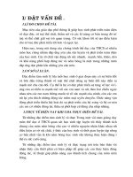
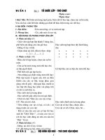
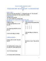
FIGURE 1:
PICkit™ 1 FLASH STARTER KIT
PRINTED CIRCUIT BOARD
INTRODUCTION
The PICkit™ 1 FLASH Starter Kit is a low cost
programmer for Microchip's 8/14-pin FLASH
microcontrollers. On the surface, the PICkit 1 is an
easy to use programmer. What may not be so obvious
to its user is the PICkit 1 is also a useful design
example illustrating primarily two things: (1) a
Windows®-based low speed USB application and (2)
a simple boost power supply design. This application
note discusses all aspects of design that went into
creating the PICkit 1. This application note will explore
in detail the hardware design, Windows-based software, and PIC16C745 firmware. The following is a list
of features that make the PICkit 1 a useful design
example.
• USB Benefits
- Plug and play
- Non-bulky cables
- No driver development needed (for Human
Interface Device class)
- Powered by PC (extra cable not needed)
• Low cost boost power supply
- Firmware implemented PID control
- Use of on-board CCP and ADC
- Software configurable VPP level from 9V to
14V
• Windows-based programming Interface
- Simple ASCII based communication with
device
- Portable Visual Basic USB functions
2003 Microchip Technology Inc.
USB SIDE OF THINGS
USB devices have provided consumers with easy to
use peripherals. The advantages of USB peripherals
are numerous over earlier peripheral communication
protocols, namely the serial and parallel ports. A standardized cable is used for all USB peripherals and the
cable itself is less bulky compared to serial or parallel
cables. USB connectors are distinguishable from one
end to the other and are small and convenient. As
laptop computers, PDAs and tablet PCs become
slimmer and more compact, fewer and fewer support
the previous peripheral protocols. USB devices can be
bus powered, or powered directly by the PC, therefore
eliminating the need for an extra power cord. USB
devices are hot pluggable without risking damage to
the PC or device. As a result of these benefits, peripheral developers are almost exclusively developing
USB devices. For the developer who knows very little
about the USB specification, this can be a daunting
task. In an attempt to alleviate this task, this section will
detail the software and firmware used to create USB
communication between the PICkit 1 programmer
board and PICkit 1 Graphical User Interface (GUI).
Both the firmware and software can easily be modified
to fit a variety of other applications.
DS00258A-page 1
AN258
Implementation: Firmware
The PIC16C745 is Microchip's low speed USB
microcontroller used to facilitate USB communication
between the host computer and the PICkit 1 programmer board. The PIC16C745's on-chip USB peripheral,
or Serial Interface Engine (SIE), provides the lowest
level interface to the USB. Microchip provides USB
Support Firmware to provide a mid-level interface
between the SIE and main loop in the application. This
firmware, also called the Ch. 9 library firmware,
primarily implements the functionality described in Ch. 9
of the USB Specification, version 1.1. Ch. 9 describes
what requests the host makes of a USB device and how
the device responds appropriately to these requests.
Get and Put functions are provided in the Ch. 9 library
to facilitate moving data onto and off of the bus in the
main loop. The USB Support Firmware was used as a
starting place to develop the PICkit 1 firmware.
The USB Support Firmware is more than just a library,
it is also a working demo. The firmware creates a
device that enumerates as a USB mouse and then
sends mouse data that causes the cursor to move in a
circle. This functionality was replaced by the functionality the PICkit 1 requires. Two things were changed: (1)
the USB descriptors and (2) the main loop. Initialization
of the SIE (Serial Interface Engine) was left the same
as found in the USB Support Firmware. USB
initialization consists of calling the function InitUSB and
macro ConfiguredUSB.
Note:
ConfiguredUSB sets the Zero flag
(STATUS, Z) when the device is configured. The device must be configured in
order to send or receive user data. The
device must reach the configured state
before using GetEP1 or PutEP1.
DESCRIPTORS
The first thing altered in the USB Support Firmware
was the descriptors. Descriptors describe to the host
what information will be sent to the host. For the PICkit
1 application, generic data is sent back and forth to the
host via Endpoint 1. By utilizing the Human Interface
Device (HID) class, it is possible to create a device that
does not require the development of a driver on the
host side. HID devices are supported automatically by
Microsoft® Windows (98 SE and later.) Therefore, the
descriptors for the PICkit 1 describe a vendor-defined
HID class device that sends eight bytes to and from the
host via Endpoint One. The vendor-defined designation is made in the report descriptor, a descriptor
required by HID devices. This designation makes it
possible to use the Jan Axelson functions discussed
later in this document in “Implementation: Software”. All
descriptors are listed with comments in Appendix A.
These descriptors are easily transferable to another
DS00258A-page 2
application, with the exception that the vendor ID
(owned by Microchip) and string descriptors be
changed.
Note:
The PICkit 1 descriptors describe two
configurations. For the purposes of this
application note the second configuration
can be ignored. This configuration was
created so that the PICkit 1 can interface
with Macintosh® computers. Non-HID
descriptors are more easily interfaced by
the Macintosh operating system.
MAIN LOOP
The main loop of the PICkit 1 firmware accomplishes
the following primary tasks:
1.
2.
3.
4.
Services USB flags
Receives commands and data from the host
Transmits requested data to the host
Translates ASCII commands into actions
Servicing the flags generated by the Serial Interface
Engine (SIE) is accomplished by calling the function
ServiceUSB. This function must be called at least once
every 50 ms in order to maintain reliable USB communication. The critical USB flags are serviced in the interrupt service routine (ISR) so this was left unchanged
from the USB Support Firmware. All USB flags are
serviced by ServiceUSB and the ISR, so other than
polling ServiceUSB, the Ch.9 library makes handling
USB requests transparent to the developer. A simple
Get/Put interface is provided by the Ch.9 library to
make getting data from and sending data over the USB
easy to implement in the main loop.
Data is received from the host computer by the GetEP1
function (GetEP2 is provided if Endpoint 2 is the
desired OUT endpoint.) This function is polled until the
carry flag is set. The carry flag (STATUS, C) is set when
the endpoint buffer is full, indicating data has been
received from the host. GetEP1 transfers the data from
the endpoint buffer to the user's buffer defined at the
address pointed to by the FSR register and IRP bit.
This parameter must be set up prior to polling the
GetEP1 function. GetEP1 returns the number of bytes
received in W.
Data is sent to the host in a similar fashion, using the
PutEP1 function. Before calling PutEP1, the buffer
where data is waiting to be sent to the host must be
pointed to by the FSR register and IRP bit, and length
of the buffer loaded into in the W register. If the
endpoint buffer is empty, the carry flag will be sent after
calling PutEP1, indicating that the data will successfully
be sent to the host. PutEP1 should be polled until the
carry flag is set in order to ensure the data is sent to the
host successfully.
2003 Microchip Technology Inc.
AN258
“Implementation: Software” talks about the ASCII
commands sent by the host to the PIC16C745. The
PIC16C745 translates these commands into actions.
For instance, a “P” received from the host corresponds
to the action “Enter Programming mode.” The firmware
interprets this command into the necessary action by
toggling VDD and VPP to the 8/14-pin FLASH microcontroller in the appropriate sequence so that the 8/14-pin
device enters Programming mode. All programming
commands cause the PIC16C745 to initiate the
corresponding actions defined in the programming
specifications for the 8/14-pin FLASH microcontrollers
(DS41173 Rev B, DS41191 Rev B.)
Note:
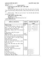
FIGURE 2:
PICkit 1 FLASH STARTER
KIT GUI INTERFACE
The specifics of the bit bang operations
performed for each command are left to
the reader to explore in the PICkit 1
PIC16C745
firmware
(extensively
commented) included with this application note, and/or in the PIC12F629/675
and PIC16F630/16F676 programming
specifications.
Implementation: Software
The Graphical User Interface (GUI) for PICkit 1 was
written using Visual Basic® 6.0. This section will
explore the low level interface of the Visual Basic®
software that communicates with the PIC16C745 via
USB link. In addition, the high level interface, where the
host directs the programming process, will be discussed briefly. The high level interface is not discussed
in depth as it is unlikely the reader will want to adapt
this functionality to his/her application. The software
and firmware are extensively commented should the
reader be curious. Figure 2 shows what the PICkit 1
Visual Basic® based GUI looks like.
Low Level Details
Much of this section is adapted from Jan Axelson's
book, “USB Complete, 2nd edition.” In Chapters 15 and
16 she discusses in depth, the Windows API functions
that are available for interfacing to HID devices. Also,
these chapters show how to declare and call the
functions in both Visual C++® and Visual Basic®. This
application note limits the scope of describing these
functions to the Visual Basic® functions utilized in the
PICkit 1 software.
The host will enumerate a device as soon as the device
is connected to the computer. At this point, the device
can be accessed from any Windows application. Jan
Axelson describes the process for interfacing with a
HID using the HID class application calls. The code to
do this is available from Jan's web site www.lvr.com,
both in Visual C++® and Visual Basic®, usbhidio2c.zip
and usbhidio2.zip respectively. The function declaration modules included in the PICkit 1 software are spinoffs from the modules in these examples. The following
paragraphs describe the process by which the PICkit 1
identifies and communicates with PICkit 1.
2003 Microchip Technology Inc.
DS00258A-page 3
AN258
Low Level Programming
The first function call is HID_GetHidGuid. This is done
in order to get the GUID, or Globally Unique Identifier,
for the HID class. Once this is done, SetupDiGetClassDev is used to get a list of the enumerated HID devices.
The software searches the list for a device matching
the PICkit's product and vendor IDs. If a match is found,
the device's correct interface is found using SetupDiEnumDeviceInterface. The application then calls SetupDiEnumDeviceInterfaceDetail to get the device path.
With this information, the application can open the
device using CreateFile and communicate using
standard IO Calls, ReadFile and WriteFile. This
process is greatly abbreviated. Refer to Ch. 16 of “USB
Complete” or the PICkit 1 software listing for details.
The PICkit 1 implements this process within the
ReadReport and WriteToDevice functions. This
eliminates the need for a separate OpenFile function.
These functions keep track of whether a device is
found, and if not, run though the process to find it.
Developers adapting the PICkit 1 software to their own
needs can use ReadReport and WriteToDevice outright
without dealing with the process described in the
previous paragraph. These functions are explained in
more detail in the next paragraphs.
ReadReport returns a buffer from the USB device.
PICkit 1 uses overlapped reads and writes. That means
rather than blocking the process waiting for a buffer to
be returned from the device, ReadReport immediately
returns the oldest buffer received. If no buffer has been
received, it still returns immediately with an error code.
While non-overlapped reads may seem simpler, it
presents a problem in that it blocks the process until the
buffer has been returned. The process could wait
forever if the board is not attached.
The following is a list of function parameters:
• Inputs - None from process. Uses constants for
vendor and device IDs
• Outputs - ReadBuffer, global array of 8 bytes
• Status - Result, global integer
WriteToDevice sends an 8 byte command buffer to the
device. The command is passed as a string type.
Internally, WriteToDevice copies the string over to an
array of 8 bytes. A leading '0' is used by the HID class
driver as a report ID.
The following is a list of function parameters:
• Inputs - Command string
• Outputs - None
• Status - Result, global integer
One limitation to ReadReport and WriteToDevice is that
they require communication to occur 8 bytes at a time.
Short packets are not allowed, so OUT transactions are
padded with a null command to the device. Likewise IN
transactions are padded with null bytes. The next
section will clarify this issue.
DS00258A-page 4
PICkit 1 is supported on Windows® 98SE, Windows®
ME, Windows® 2000, and Windows® XP. PICkit 1 will
not work on Windows® NT or Windows® 98 Gold. The
reason PICkit 1 will not work on Windows 98 Gold is
that the PICkit 1 uses an Interrupt OUT endpoint.
Interrupt OUT endpoints were not introduced until
version 1.10 of the USB Specification. Windows 98
Gold supported only version 1.00.
HIGH LEVEL PROGRAMMING
The PICkit 1 PIC16C745 device implements only the
most primitive programming operations, very closely
aligned with the actual programming commands
provided in the part. These commands are described in
the PIC12F629/675 and PIC16F630/676 programming
specifications. It is the host that directs the sequence of
these primitive functions in order to implement the
programming of the 8/14-pin device. This was done so
that as long as the command table doesn't change from
device to device, future devices of varying memory
sizes can be accommodated with only a change to host
software, not firmware.
Currently there are thirteen commands implemented:
• 'P' - Enter Programming mode. Enables Programming mode in the device. Must be done
before any other commands can be
executed.
• 'p' - Exit Programming mode. Shuts down
Programming mode.
• 'E' - Bulk erase program memory
• 'e' - Bulk erase data memory
• 'W' -Write program memory and increment PC to
the next word address
• 'D' - Write byte to EE Data memory
• 'C' - Advance PC to Configuration memory
(0x2000)
• 'I' - Increment address n times
• 'R' - Read four words from program memory
• 'r' - read eight bytes from EE Data memory
• 'V' - Control device power and 2.5 kHz control
• 'v' - Return firmware version, three bytes
<major>, <minor>, <dot>
• 'S' - Calculate checksums for both Program
memory and EE Data memory.
• 'Z' - Null command, used to pad out the 8 byte
command packets
Commands are packed conveniently into the 8 byte
packets (e.g., Write commands take three bytes: 'W',
<high byte>, <low byte>). Two of these are packed into
each 8 byte packet and the last two bytes are padded
with null commands. The Read commands read as
much as will fit into a return packet. Read Program
memory reads and returns 4 words; Read EE Data
returns 8 bytes. Since eight of these commands can be
packed into each OUT transaction, 32 words or 64
bytes may be read as a result of one OUT transaction.
2003 Microchip Technology Inc.
AN258
Implementation: Hardware
The erase process is complicated by calibration values
that must be preserved. The OSCCAL value is stored
at the last location of program memory and the
Bandgap calibration is in the high order bits of the
configuration word. These must be read prior to erasing
and restored after the erase.
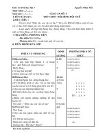
The hardware developed for the PICkit 1 FLASH
Starter Kit intentionally uses as few components as
necessary to keep the cost low. Most of the components on the PICkit 1 programmer board make up the
boost power supply. The boost power supply, shown in
Figure 3, creates the 13V voltage needed for programming Microchip's low pin count FLASH devices. CCP1
runs in PWM mode to create the input to the boost
circuit. Timer2 sets the period of the PWM. An A/D
channel (RA1) provides feedback to the PIC16C745.
THE BOOST POWER SUPPLY
A boost power supply is needed on the PICkit 1
programmer board in order to create the programming
voltage (VPP) called for in the PIC12F629/675
programming specification. The boost power supply is
a combination of hardware and firmware design.
GP1/ICSPCLK
ICSP_CLK
GP0/ICSPDATA
ICSP_DATA
VDD
R22
10K
Q4
2N3906
C5
0.1 µF
VPP
+5_SWITCHED
PIC12F6XX
+5V
GP3/MCLR/VPP
PROGRAMMING HARDWARE
3
FIGURE 1-1:
VPP is switched on and off by pin RA0. Similarly, RB7
switches power to VDD. Finally, RC6 and RC7 bit bang
programming commands to the device.
3
Q3
2N3904
R14
10K
R13
100K
2
1
3
R19
Q1
2
10K 2N3906
R11
2.7K
R10
4.7K
VDD_ENABLE
ICSP_DATA
ICSP_CLK
RB7
RC7/RX/DT
RC6/TX/CK
VPP_OFF
RA0/AN0
PIC16C745
VPP_FEEDBACK
RA1/AN1
RC2/CCP1
VPP_PUMP
10K
2
Q2
2N3904
+ C3
10 µF
16V
R9
L1
3
680 µH
C1
0.1 µF
10K
+ C4
47 µF
25V
D13
1N5817
1
+5V
1
R12
2
1
2003 Microchip Technology Inc.
DS00258A-page 5
AN258
Details on how a boost circuit works are discussed in
Technical Brief TB053. What happens briefly is that
when Q2 is turned on, inductor L1 charges. When Q2
is switched off, the energy stored in L1 flows through
D13 to the storage capacitor (C4) and load. Q3 and Q4
make up a switch for turning VPP on and off to the
FLASH device. The switch is toggled on and off by
RA0. Assuming the resistive load is the held constant,
VPP will change with respect to the energy released
from L1. L1 stores energy during the high phase of the
PWM and releases energy during the low phase of the
PWM. This boost circuit runs in Discontinuous mode,
meaning L1 will always discharge fully during the low
phase of the PWM. VPP increases as the duty cycle of
the PWM increases. The stability of VPP is achieved
with a firmware PID.
Pk, Ik, and Dk are all functions of the difference
between the Set Point (SP) and Present Variable (PV).
This difference is the error (ek) for a present cycle.
Equation 2 shows this relation.
Implementation: Firmware
EQUATION 2:
The boost circuit routines are located in two linked files:
pid.asm and VPPCntl.asm. VPPCntl.asm contains the
functions for initializing the PIC16C745 peripherals
used to generate the boost circuit, turning VPP and VDD
on and off, and clamping VPP high or low. This file also
contains the DoSwitcher function which is called from
the ISR when Timer2 interrupts. Timer2 is set up to
overflow at a frequency of 93.75 kHz. The Timer2
postscaler is 1:16, therefore the Timer2 interrupt occurs
at a frequency of 5.86 kHz. DoSwitcher reads the A/D
value generated on the boost circuit feedback pin.
DoSwitcher then transfers this value to the PID function
where a correction factor is calculated. Several
parameters are defined at the head of VPPCntl.asm.
They are described in Table 1.
TABLE 1:
EQUATION 1:
CVk+1 = Pk + Ik + Dk
ek = SP - PVk
The proportional term in Equation 1 is directly proportional to ek. It is defined as ek multiplied by the proportionality gain constant, Kp (Equation 3). The
proportional term's contribution to the output is based
only on the amount of error. By increasing Kp, the
response time of the output decreases and the
overshoot increases. If Kp is too large the system will
be unstable. In summary, Pk compensates for a change
in what CV currently is and what it needs to be.
EQUATION 3:
Pk = Kpek
PARAMETER
Parameter
Description
VCHECK
ADC value corresponding to VPP =
13V
PWM_MAX
Max duty cycle
skip_reload
Number of TMR2 interrupts between
reading ADC
PID control is used to stabilize VPP. From a control
standpoint the boost circuit looks like the following
system:
FIGURE 3:
BOOST CIRCUIT DIAGRAM
e
SP
+
Any increase or decrease in the duty cycle causes a
respective rise or fall in VPP. The variable governing the
duty cycle is the control variable (CV). The control
variable is calculated for the next cycle based on the
proportional, integral and differential analysis of the
feedback. Equation 1 shows this relation.
PWM
Control
PV
DS00258A-page 6
CV
Boost
Circuit
Y
The integral term Ik is equal to the previous integral
calculation plus the deviation from the Set Point, ek,
multiplied by the integration gain constant, Ki
(Equation 4). From a conceptional standpoint, Ik effects
the output based on how long the error has been
around, as well as the amount of error. The longer the
error is present, the greater Ik contributes to changing
the output. Ik tends to integrate the error to zero.
EQUATION 4:
Ik = Ik-1 + Kiek
The final contribution to Equation 1 is the derivative
term. This term is equal to the derivative gain constant,
Kd, multiplied by the difference between the previous
deviation from the Set Point, ek-1, and the current
deviation, ek. The derivative term affects the output
based on the rate of change of the error. The faster the
rate of change of the error, the greater affect this term
has on the output. Dk compensates for a dynamically
changing CV requirement.
2003 Microchip Technology Inc.
AN258
EQUATION 5:
Dk = Kd (ek-1 – ek )
Trial and error was used to find the values of Kp, Ki, and
Kd that gave VPP the best balance between rise time,
stability and overshoot. These values are defined in
pid.inc.
Conclusion
The USB design for the PICkit 1 FLASH starter kit is
very versatile and can be used in a variety of other
applications with minimal changes to its firmware and
Visual Basic software. For developers looking to create
a Windows-based USB application using the
PIC16C745, the PICkit 1 design offers a ready made
example of how to do it. In addition, the PICkit 1 also
provides an example of boost circuit design using
minimal components. As a design example, the PICkit
1 offers more to engineers than just a low cost PIC®
MCU programmer.
References
• Jan Axelson, “USB Complete, Second Edition”, ©
2001, Lakeview Research, Madison, WI
• Jan Axelson’s website: www.lvr.com
• PICkit™ 1 User's Guide (DS40051C)
• PIC12F629/675 Programming Specification
(DS41173C)
• TB053, “Generating High Voltage Using the
PIC16C781/782” (DS91053A)
• Universal Serial Bus Specification, Revision 1.1 ©
1998, Compaq Computer Corporation, Intel
Corporation, Microsoft Corporation, NEC
Corporation
• HID Class Definition, revision 1.1 © 1998,
Compaq Computer Corporation, Intel
Corporation, Microsoft Corporation, NEC
Corporation
• USB Support Firmware User’s Guide
2003 Microchip Technology Inc.
DS00258A-page 7
AN258
NOTES:
DS00258A-page 8
2003 Microchip Technology Inc.
AN258
APPENDIX A:
USB DESCRIPTORS
Descriptor fields defined in Ch9 of USB Specification and HID Class Definition
Device Descriptor
0x12
0x01
0x10
0x01
0x00
0x00
0x00
0x08
0xD8
0x04
0x32
0x00
0x00
0x00
0x01
0x02
0x00
0x02
;
;
;
;
;
;
;
;
;
;
;
;
;
;
;
;
;
;
bLength
bDescType
bcdUSBUSB
bDeviceClass
bDeviceSubClass
bDeviceProtocol
bMaxPacketSize0
idVendor
idProduct
bcdDevice
iManufacturer
iProduct
iSerialNumber
bNumConfigs
Configuration Descriptor 1 (Index 0)
0x09
; bLength
0x02
; bDescType
0x29
; wTotalLength
0x00
0x01
; bNumInterfaces
0x01
; bConfigValue
0x03
; iConfig
0x80
; bmAttributes
0x32
; MaxPower
Interface Descriptor
0x09
; bLength
0x04
; bDescType
0x00
; bInterfaceNum
0x00
; bAlternatSet
0x02
; bNumEndpoints
0x03
; bInterfaceClass
0x00
; bIntrfcSubClass
0x00
; bIntrfcProtocol
0x00
; iInterface
HID Descriptor
0x09
; bLength
0x21
; bDescType
0x00
; bcfHID
0x01
0x00
; bCountryCode
0x01
; bNumDescriptors
0x22
; bDescType
0x1D
; bDescLength
0x00
Endpoint Descriptor
0x07
; bLength
0x05
; bDescType
0x81
; bEndpointAddr
0x03
; bmAttributes
0x08
; wMaxPacketSize
0x00
0x0A
; bInterval
Endpoint Descriptor
0x07
; bLength
0x05
; bDescType
0x01
; bEndpointAddr
2003 Microchip Technology Inc.
Length of descriptor
This is a DEVICE descriptor
USB spec. revision 1.10 (low byte)
(high byte)
0x04D8 is Microchip's Vendor ID
(high byte)
Product ID = 50 (low byte)
(high byte)
(low byte)
(high byte)
String Index = 1
String Index = 2
0
2 configurations
Length of descriptor
This is a CONFIGURATION descriptor
Total length of all descriptors in
this configuration
Number of interfaces in this config
Configuration Value
String Index = 3
bus powered, remote wakeup disabled
100mA (2mA*32h)
Length of descriptor
This is an INTERFACE descriptor
number of interface, 0 based array
Alternate setting - N/A
# of endpoints in this interface
assigned by the USB
Not A boot device
none
String Index = 0 (none)
Length of descriptor
This is an HID descriptor
HID spec. revision 1.00 (low byte)
(high byte)
Localized country code (none)
# of HID class descriptors
Report descriptor type
Length of Report descr. (low byte)
(high byte)
Length of descriptor
This is an ENDPOINT descriptor
EP1, In
Transfer Type: Interrupt
Maximum packet size (low byte)
(high byte)
polling interval: 10ms
Length of descriptor
EP1, OUT
DS00258A-page 9
AN258
0x03
0x08
0x00
0x0a
; bmAttributes
; wMaxPacketSize
; bInterval
Configuration Descriptor 2 (Index 1)
0x09
; bLength
0x02
; bDescType
0x20
; wTotalLength
0x00
0x01
; bNumInterfaces
0x02
; bConfigValue
0x04
; iConfig
0x80
bmAttributes
0x32
; MaxPower
Interface Descriptor
0x09
; bLength
0x04
; bDescType
0x00
; bInterfaceNum
0x00
; bAlternatSet
0x02
; bNumEndpoints
0xFF
; bInterfaceClass
0x00
; bIntrfcSubClass
0x00
; bIntrfcProtocol
0x00
; iInterface
Endpoint Descriptor
0x07
; bLength
0x05
; bDescType
0x81
; bEndpointAddr
0x03
; bmAttributes
0x08
; wMaxPacketSize
0x00
0x0A
; bInterval
Endpoint Descriptor
0x07
; bLength
0x05
; bDescType
0x01
; bEndpointAddr
0x03
; bmAttributes
0x08
; wMaxPacketSize
0x00
0x0a
; bInterval
ReportDescriptor
0x06, 0x00, 0xff
0x09, 0x01
0xa1, 0x01
0x19, 0x01
0x29, 0x08
0x15, 0x00
0x26, 0xff, 0x00
0x75, 0x08
0x95, 0x08
0x81, 0x02
0x19, 0x01
0x29, 0x08
0x91, 0x02
0xc0
DS00258A-page 10
;
;
;
;
;
;
;
;
;
;
;
;
;
;
Interrupt
Maximum packet size (low byte)
(high byte)
polling interval: 10ms
Length of descriptor
This is a CONFIGURATION descriptor
Total length of all descriptors in
this configuration
Number of interfaces in this config
Configuration Value
String Index = 4
bus powered, remote wakeup disabled
100mA (2mA*32h)
Length of descriptor
This is an INTERFACE descriptor
number of interface, 0 based array
Alternate setting - N/A
# of endpoints in this interface
assigned by the USB
Not A boot device
none
String Index = 0 (none)
Length of descriptor
This is an ENDPOINT descriptor
EP1, In
Transfer Type: Interrupt
Maximum packet size (low byte)
(high byte)
polling interval: 10ms
Length of descriptor
EP1, OUT
Interrupt
Maximum packet size (low byte)
(high byte)
polling interval: 10ms
USAGE_PAGE (Vendor Defined Page 1)
USAGE (Vendor Usage 1)
COLLECTION (Application)
USAGE_MINIMUM (Vendor Usage 1)
USAGE_MAXIMUM (Vendor Usage 8)
LOGICAL_MINIMUM (0)
LOGICAL_MAXIMUM (255)
REPORT_SIZE (8)
REPORT_COUNT (8)
INPUT (Data,Var,Abs)
USAGE_MINIMUM (Vendor Usage 1)
USAGE_MAXIMUM (Vendor Usage 8)
OUTPUT (Data,Var,Abs)
END_COLLECTION
2003 Microchip Technology Inc.
AN258
String1*
"Microchip Technology Inc."
String2*
"PICkit™ 1 FLASH Starter Kit"
String3*
"Config. 1: HID"
String4*
"Config. 2: non-HID"
*Strings written in unicode format.
2003 Microchip Technology Inc.
Refer to firmware for details.
DS00258A-page 11
AN258
APPENDIX B:
SOURCE CODE
The complete source code, including the application
software and device firmware are available for
download as a single archive file from the Microchip
corporate web site at:
www.microchip.com
DS00258A-page 12
2003 Microchip Technology Inc.
Note the following details of the code protection feature on Microchip devices:
•
Microchip products meet the specification contained in their particular Microchip Data Sheet.
•
Microchip believes that its family of products is one of the most secure families of its kind on the market today, when used in the
intended manner and under normal conditions.
•
There are dishonest and possibly illegal methods used to breach the code protection feature. All of these methods, to our
knowledge, require using the Microchip products in a manner outside the operating specifications contained in Microchip's Data
Sheets. Most likely, the person doing so is engaged in theft of intellectual property.
•
Microchip is willing to work with the customer who is concerned about the integrity of their code.
•
Neither Microchip nor any other semiconductor manufacturer can guarantee the security of their code. Code protection does not
mean that we are guaranteeing the product as “unbreakable.”
Code protection is constantly evolving. We at Microchip are committed to continuously improving the code protection features of our
products. Attempts to break microchip’s code protection feature may be a violation of the Digital Millennium Copyright Act. If such acts
allow unauthorized access to your software or other copyrighted work, you may have a right to sue for relief under that Act.
Information contained in this publication regarding device
applications and the like is intended through suggestion only
and may be superseded by updates. It is your responsibility to
ensure that your application meets with your specifications.
No representation or warranty is given and no liability is
assumed by Microchip Technology Incorporated with respect
to the accuracy or use of such information, or infringement of
patents or other intellectual property rights arising from such
use or otherwise. Use of Microchip’s products as critical
components in life support systems is not authorized except
with express written approval by Microchip. No licenses are
conveyed, implicitly or otherwise, under any intellectual
property rights.
Trademarks
The Microchip name and logo, the Microchip logo, dsPIC,
KEELOQ, MPLAB, PIC, PICmicro, PICSTART, PRO MATE and
PowerSmart are registered trademarks of Microchip
Technology Incorporated in the U.S.A. and other countries.
FilterLab, microID, MXDEV, MXLAB, PICMASTER, SEEVAL
and The Embedded Control Solutions Company are
registered trademarks of Microchip Technology Incorporated
in the U.S.A.
Accuron, Application Maestro, dsPICDEM, dsPICDEM.net,
ECONOMONITOR, FanSense, FlexROM, fuzzyLAB, InCircuit Serial Programming, ICSP, ICEPIC, microPort,
Migratable Memory, MPASM, MPLIB, MPLINK, MPSIM,
PICC, PICkit, PICDEM, PICDEM.net, PowerCal, PowerInfo,
PowerMate, PowerTool, rfLAB, rfPIC, Select Mode,
SmartSensor, SmartShunt, SmartTel and Total Endurance are
trademarks of Microchip Technology Incorporated in the
U.S.A. and other countries.
Serialized Quick Turn Programming (SQTP) is a service mark
of Microchip Technology Incorporated in the U.S.A.
All other trademarks mentioned herein are property of their
respective companies.
© 2003, Microchip Technology Incorporated, Printed in the
U.S.A., All Rights Reserved.
Printed on recycled paper.
Microchip received QS-9000 quality system
certification for its worldwide headquarters,
design and wafer fabrication facilities in
Chandler and Tempe, Arizona in July 1999
and Mountain View, California in March 2002.
The Company’s quality system processes and
procedures are QS-9000 compliant for its
PICmicro® 8-bit MCUs, KEELOQ® code hopping
devices, Serial EEPROMs, microperipherals,
non-volatile memory and analog products. In
addition, Microchip’s quality system for the
design and manufacture of development
systems is ISO 9001 certified.
2003 Microchip Technology Inc.
DS00258A-page 13
WORLDWIDE SALES AND SERVICE
AMERICAS
ASIA/PACIFIC
Corporate Office
Australia
2355 West Chandler Blvd.
Chandler, AZ 85224-6199
Tel: 480-792-7200 Fax: 480-792-7277
Technical Support: 480-792-7627
Web Address:
Microchip Technology Australia Pty Ltd
Marketing Support Division
Suite 22, 41 Rawson Street
Epping 2121, NSW
Australia
Tel: 61-2-9868-6733 Fax: 61-2-9868-6755
Atlanta
3780 Mansell Road, Suite 130
Alpharetta, GA 30022
Tel: 770-640-0034 Fax: 770-640-0307
China - Beijing
2 Lan Drive, Suite 120
Westford, MA 01886
Tel: 978-692-3848 Fax: 978-692-3821
Microchip Technology Consulting (Shanghai)
Co., Ltd., Beijing Liaison Office
Unit 915
Bei Hai Wan Tai Bldg.
No. 6 Chaoyangmen Beidajie
Beijing, 100027, No. China
Tel: 86-10-85282100 Fax: 86-10-85282104
Chicago
China - Chengdu
333 Pierce Road, Suite 180
Itasca, IL 60143
Tel: 630-285-0071 Fax: 630-285-0075
Microchip Technology Consulting (Shanghai)
Co., Ltd., Chengdu Liaison Office
Rm. 2401-2402, 24th Floor,
Ming Xing Financial Tower
No. 88 TIDU Street
Chengdu 610016, China
Tel: 86-28-86766200 Fax: 86-28-86766599
Boston
Dallas
4570 Westgrove Drive, Suite 160
Addison, TX 75001
Tel: 972-818-7423 Fax: 972-818-2924
Detroit
Tri-Atria Office Building
32255 Northwestern Highway, Suite 190
Farmington Hills, MI 48334
Tel: 248-538-2250 Fax: 248-538-2260
Kokomo
2767 S. Albright Road
Kokomo, IN 46902
Tel: 765-864-8360 Fax: 765-864-8387
Los Angeles
18201 Von Karman, Suite 1090
Irvine, CA 92612
Tel: 949-263-1888 Fax: 949-263-1338
Phoenix
2355 West Chandler Blvd.
Chandler, AZ 85224-6199
Tel: 480-792-7966 Fax: 480-792-4338
San Jose
Microchip Technology Inc.
2107 North First Street, Suite 590
San Jose, CA 95131
Tel: 408-436-7950 Fax: 408-436-7955
Toronto
6285 Northam Drive, Suite 108
Mississauga, Ontario L4V 1X5, Canada
Tel: 905-673-0699 Fax: 905-673-6509
China - Fuzhou
Microchip Technology Consulting (Shanghai)
Co., Ltd., Fuzhou Liaison Office
Unit 28F, World Trade Plaza
No. 71 Wusi Road
Fuzhou 350001, China
Tel: 86-591-7503506 Fax: 86-591-7503521
China - Hong Kong SAR
Microchip Technology Hongkong Ltd.
Unit 901-6, Tower 2, Metroplaza
223 Hing Fong Road
Kwai Fong, N.T., Hong Kong
Tel: 852-2401-1200 Fax: 852-2401-3431
China - Shanghai
Microchip Technology Consulting (Shanghai)
Co., Ltd.
Room 701, Bldg. B
Far East International Plaza
No. 317 Xian Xia Road
Shanghai, 200051
Tel: 86-21-6275-5700 Fax: 86-21-6275-5060
China - Shenzhen
Microchip Technology Consulting (Shanghai)
Co., Ltd., Shenzhen Liaison Office
Rm. 1812, 18/F, Building A, United Plaza
No. 5022 Binhe Road, Futian District
Shenzhen 518033, China
Tel: 86-755-82901380 Fax: 86-755-8295-1393
China - Qingdao
Rm. B505A, Fullhope Plaza,
No. 12 Hong Kong Central Rd.
Qingdao 266071, China
Tel: 86-532-5027355 Fax: 86-532-5027205
India
Microchip Technology Inc.
India Liaison Office
Marketing Support Division
Divyasree Chambers
1 Floor, Wing A (A3/A4)
No. 11, O’Shaugnessey Road
Bangalore, 560 025, India
Tel: 91-80-2290061 Fax: 91-80-2290062
Japan
Microchip Technology Japan K.K.
Benex S-1 6F
3-18-20, Shinyokohama
Kohoku-Ku, Yokohama-shi
Kanagawa, 222-0033, Japan
Tel: 81-45-471- 6166 Fax: 81-45-471-6122
Korea
Microchip Technology Korea
168-1, Youngbo Bldg. 3 Floor
Samsung-Dong, Kangnam-Ku
Seoul, Korea 135-882
Tel: 82-2-554-7200 Fax: 82-2-558-5934
Singapore
Microchip Technology Singapore Pte Ltd.
200 Middle Road
#07-02 Prime Centre
Singapore, 188980
Tel: 65-6334-8870 Fax: 65-6334-8850
Taiwan
Microchip Technology (Barbados) Inc.,
Taiwan Branch
11F-3, No. 207
Tung Hua North Road
Taipei, 105, Taiwan
Tel: 886-2-2717-7175 Fax: 886-2-2545-0139
EUROPE
Austria
Microchip Technology Austria GmbH
Durisolstrasse 2
A-4600 Wels
Austria
Tel: 43-7242-2244-399
Fax: 43-7242-2244-393
Denmark
Microchip Technology Nordic ApS
Regus Business Centre
Lautrup hoj 1-3
Ballerup DK-2750 Denmark
Tel: 45-4420-9895 Fax: 45-4420-9910
France
Microchip Technology SARL
Parc d’Activite du Moulin de Massy
43 Rue du Saule Trapu
Batiment A - ler Etage
91300 Massy, France
Tel: 33-1-69-53-63-20 Fax: 33-1-69-30-90-79
Germany
Microchip Technology GmbH
Steinheilstrasse 10
D-85737 Ismaning, Germany
Tel: 49-89-627-144-0
Fax: 49-89-627-144-44
Italy
Microchip Technology SRL
Via Quasimodo, 12
20025 Legnano (MI)
Milan, Italy
Tel: 39-0331-742611 Fax: 39-0331-466781
United Kingdom
Microchip Ltd.
505 Eskdale Road
Winnersh Triangle
Wokingham
Berkshire, England RG41 5TU
Tel: 44-118-921-5869 Fax: 44-118-921-5820
05/30/03
DS00258A-page 14
2003 Microchip Technology Inc.