CCNA Lab Exercise - Configuring The PIX Firewall With PDM
Bạn đang xem bản rút gọn của tài liệu. Xem và tải ngay bản đầy đủ của tài liệu tại đây (399.61 KB, 21 trang )
Lab Exercise—Configuring the PIX Firewall
with PDM
Objectives
In this lab exercise you will complete the following tasks:
n
Install PDM.
n
Configure inside to outside access through your PIX Firewall using PDM.
n
Configure outside to inside access through the PIX Firewall using PDM.
n
Allow ICMP traffic
n
Configure PIX IDS
n
Configure Site to Site IPSec VPNs
n
Test and verify the PDM operation.
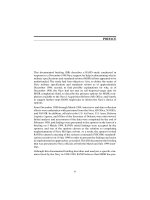
Visual Objectives
The following figure displays the topology of the lab environment used in this
exercise.
Lab Visual Objective
192.168.P.254
Internet
To adjacent pod
P1-P2
P3-P4
P5-P6
P7-P8
P9-P10
192.168.P.0/24
e0 outside .1
172.16.1.0/24
PIX Firewall
e2 dmz
172.16.1.P
e1 inside .1
.50
Bastion host
web and FTP server
10.0.P.0 /24
192.168.P.2
Internet server
web, FTP, and TFTP server
© 2001, Cisco Systems, Inc.
Copyright 2003, Cisco Systems, Inc.
.2
Inside host
www.cisco.com
CSPFA 2.0—4-32
Pix Advanced Road Show Lab 6-1
Access and Lab Setup
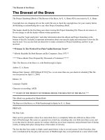
To do this lab exercise, you must be connected to the lab at www.labgear.net. Your
instructor will provide the username and password for logging into this site. Once logged on,
the lab diagram will be displayed (the picture below is for Pod #1):
To access the PIX Firewall from the main lab diagram, click on the “CONSOLE”
icon associated with the PIX Firewall. A window will open to the PIX console. To
access the inside or outside hosts, click on the appropriate ”PC Desktop” icon.
For these devices you must first authenticate at the “VNC Authentication” screen
before you can access the PC desktop.
Passwords
Use the following passwords for this lab:
PIX Advanced Road Show
n
Lab Gear password: Your instructor will provide it.
n
PIX password: Either no password (just press the Enter key) or cisco.
n
PC client or server: The username is administrator and there is no password
(just press the Enter key).
n
VNC password: When you connect to the PCs or servers, use a password of
cisco at the VNC screen.
Copyright 2003, Cisco Systems, Inc.
Task 1—Clear the PIX Firewall’s Configuration and Access
the PIX Startup Wizard
Complete the following steps to erase your current PIX Firewall configuration and
access the PDM Startup Wizard.
Step 1
Erase your current PIX Firewall configuration:
pixP(config)# write erase
Erase PIX configuration in flash memory? [confirm]
Step 2
After the flash has been cleared, reload the PIX Firewall:
pixP(config)# reload
Proceed with reload? [confirm]
Step 3
When prompted to “Pre-configure the PIX Firewall through interactive
prompts [yes]?” press Enter to respond.
Step 4
Answer the questions from the interactive prompts:
Enable password [<use current password>]: (press Enter)
Clock (UTC):
Year [2003]: (Type current year and then press Enter)
Month [May]: (Type current month and then press Enter)
Day [14]: (Type current day of month and then press Enter)
Time [09:44:00]: (Type current time and then press Enter)
Inside IP address: (Type 10.0.P.1 and then press Enter)
(where P = pod number)
Inside network mask: (Type 255.255.255.0 and then press Enter)
Host name: (Type pixP and then press Enter)
(where P = pod number)
Domain name: (Type cisco.com and then press Enter)
IP address of host running PIX PDM: (Type 10.0.P.2 and then press Enter)
(where P = pod number)
Use this configuration and write to flash? (Type y and then press Enter)
Building configuration...
Cryptochecksum: 807a0ecd 574c47a9 24c164f5 c6969409
[OK]
Step 5
Access the PDM by doing the following:
1. Open a browser on the inside client and enter https://10.0.P.1.
(where P = pod number)
Note
PDM uses secure HTTP communications. Make sure you type https.
2. You may be presented with a “Security Alert” window (“You are about to
view pages over a secure connection….”), click OK.
Copyright 2003, Cisco Systems, Inc.
Pix Advanced Road Show Lab 6-3
3. You may be presented with a “Security Alert” window (“Information you
exchange with this site cannot be view or changed…”), you are asked “Do
you want to proceed?” Click on Yes.
4. The “Enter Network Password” window is presented. Do not enter a username
or password. Click OK to continue.
Note
The password that is used by PDM is the Enable password. Since we did not enter
an enable password during setup, the password is not set.
5. After a few seconds, another “Security Warning” window opens. This window
asks “Do you want to install and run “Cisco PIX Device Manager” signed
on…”. Click on Yes.
6. After a few more seconds, the “Update Config” window opens. This window
asks “This may be the first time that PDM has been used…”. Click on
Proceed.
The Startup Wizard should automatically start. You have completed this Task.
Task 2—Use the PDM Startup Wizard to Perform Basic
Configuration Tasks
The first time you use PDM, the Startup Wizard will start automatically. You can
also launch the Startup Wizard at any time by clicking on Wizards>Startup
Wizard. Complete the following steps to configure the PIX Firewall’s outside and
interfaces, and enable NAT:
Step 1
You can use the PIX Device Manager Startup Wizard to setup a basic
configuration for your PIX. Click Next.
Step 2
In the “Basic Configuration” window, verify your hostname and domain name,
then click Next.
Step 3
In the “Outside Interface Configuration” window, verify that your outside
interface speed is auto, and “Static IP Address” is selected. In the “IP Address”
field, enter 192.168.P.1 (where P = pod number). In the dropdown menu next to
“Subnet Mask”, choose 255.255.255.0. Enter 192.168.P.254 for the “Default
Gateway”, and then click Next.
Step 4
In the “Auto Update Configuration” window, leave the “Auto Update” checkbox
blank, and click Next.
Step 5
In the “Other Interfaces Configuration” window, enable the DMZ (ethernet2)
interface for 100 Mbps Ethernet Auto communication by doing the following:
1. Click on the line containing ethernet2 in the interface list to select the interface
to edit, and then click Edit….
2. In the “Edit Interface” window, select “Enable Interface” by clicking in the
checkbox.
PIX Advanced Road Show
Copyright 2003, Cisco Systems, Inc.
3. Assign the name dmz to ethernet2 by entering dmz in the “Interface Name”
field.
4. Enter 172.16.1.P in the “IP Address” field, then select 255.255.255.0 from the
dropdown menu next to “Subnet Mask”.
5. Verify that the Speed is set to auto.
6. Enter 10 in the “Security Level” field, then click OK. The “Security Level
Change” window will open and ask you if you want to proceed. Click OK.
7. You should now be back at the “Other Interfaces Configuration” window.
Note
The inside and outside interfaces were enabled earlier via the setup routine and
the PIX CLI, respectively. PIX interfaces are shut down by default.
Step 6
Click Next. The “NAT and PAT Configuration” window opens.
Step 7
Configure a global pool of addresses to be used for address translation by doing
the following:
1. Select “Use Network Address Translation”.
2. Enter 192.168.P.20 in the “Starting Global IP Address Pool” field.
(where P = pod number)
3. Enter 192.168.P.253 in the “Ending Global IP Address Pool” field.
4. Select 255.255.255.0 from the drop-down menu.
Step 8
Click Finish.
Note
You may get an “Error in sending command” when the PDM sends the commands
to the PIX Firewall. The error message should only have to do with interfaces that
are not used in this lab, and is not fatal. Click OK.
Note
PDM has an option that will allow you to see what commands are being sent to the
PIX. You can toggle this option by going to Options>Preferences. Check the box
next to “Preview commands before sending to the firewall” to turn this option on or
uncheck it to turn it off.
Task 3—Verify the Configuration Created by the PDM
Startup Wizard and Configure Security Level, Passwords,
and Statics
Complete the following steps to verify the configuration of the PIX Firewall’s
outside and DMZ interfaces, the global address pool, routing, and NAT:
Step 1
The previous Task should have left you at the PDM Home screen. Notice all of the
statistics that are available on the Home Screen.
Copyright 2003, Cisco Systems, Inc.
Pix Advanced Road Show Lab 6-5
Step 2
Click the Configuration icon near the top left of the menu bar.
Step 3
You are presented with the Configuration window. You should see tabs labeled
Access Rules, Translation Rules, VPN, Hosts/Networks, and System
Properties.
Step 4
Click the System Properties tab. Correct any errors by clicking on Edit.
1. Verify that ethernet0, ethernet1, and ethernet2 are enabled.
2. Verify that ethernet0, ethernet1, and ethernet2 are correctly named.
3. Verify that ethernet0 has a security level of 0, ethernet1 has a security level of
100, and ethernet2 has a security level of 10.
4. Verify the IP addresses and subnet masks of ethernet0, ethernet1, and
ethernet2.
Step 5
Verify the NAT configuration and global address pool you entered earlier by
doing the following:
1. Click the Translation Rules tab.
2. You should see the one translation that has been configured to this point.
Step 6
Verify the default route configuration by doing the following:
1. Click the System Properties tab
2. Under Categories on the left side of the screen, click on Routing to expand the
category.
3. Click on Static Route.
4. Verify that the outside gateway under “Gateway IP” is 192.168.P.254.
(where P = pod number)
Step 7
Configure privileged mode and Telnet passwords by doing the following:
CAUTION
Please only use lower case cisco as the password!
1. Click on Administration from the Categories tree on the left side of the panel.
Password appears under Administration.
2. Click on Password. The Password group box appears on the right side of the
panel.
3. Enter cisco in the “New Password” text box in the “Enable Password” group
box.
4. Enter cisco in the “Confirm New Password” text box in the Enable password
group box.
5. Click Apply in the “Enable Password” group box.
Note
PIX Advanced Road Show
Since PDM uses the Enable password, and you just changed it, you will be
prompted to login via the “Enter Network Password” window. Leave “User Name”
blank, and use cisco for Password.
Copyright 2003, Cisco Systems, Inc.
6. The “Enter Network Password” window will open. Type cisco in the Password
field and click OK.
7. Enter cisco in the “Old Password” text box (cisco is the default) in the “Telnet
Password” group box.
8. Enter cisco in the “New Password” text box in the “Telnet Password” group
box.
9. Enter cisco in the “Confirm New Password” text box in the “Telnet Password”
group box.
10. Click Apply in the “Telnet Password” group box. (All of the password fields
should be blank after the Apply.)
Step 8
Assign the DMZ interface a security level of 50 by doing the following:
1. Click on the System Properties tab if it is not already there.
2. Click on Interfaces under Categories.
3. Click on dmz in the Interfaces group box (don’t click on ethernet2 in the
Hardware column).
4. Click Edit. The Interface window opens.
5. Change the security level to 50 in the “Security Level” text box of the Interface
window.
6. Click OK.
7. Click OK in the “Security Level Change” window.
8. Click Apply.
Note
Step 9
If the Apply button isn’t visible, you can select any other Configuration tab and the
PDM will prompt you if you want to save the changes you have made. Click on
“Apply Changes”.
Define a static translation for the DMZ server (bastion host) by doing the
following:
1. Click on the Hosts/Networks tab.
2. Select dmz from the “Select Interface” dropdown menu at the top of this
screen.
3. In the Hosts/Networks area , click Add (middle left of the screen).
4. In the “IP Address” field of the “Create host/network” window, enter
172.16.1.50.
5. From the dropdown menu next to Mask, select 255.255.255.255.
6. Make sure that the selected Interface is dmz. If not, use the drop-down menu to
change it.
7. Enter bastion in the Name field, and click Next.
8. You should be at the NAT (Network Address Translation) window. Define a
static translation for the bastion host by selecting Static. (A box containing the
IP address of the bastion host should then appear). Click Finish.
Copyright 2003, Cisco Systems, Inc.
Pix Advanced Road Show Lab 6-7
9. Click Apply.
10. Click on the Translation Rules tab.
11. Click on the table entry that contains the rule for the bastion host. (Note that it
is currently configured to translate 172.16.1.50 to 172.16.1.50.)
12. Select Rules>Edit… from the PDM menu bar.
13. Change the “Translate Address to” IP address from 172.16.1.50 to
192.168.P.11.
14. Click OK.
15. You should be back at the Translation Rules tab of the Configuration
window. Click Apply.
Step 10 Define a static translation for the inside client by doing the following:
1. From the Translation Rules tab, select Rules>Add….
2. Select inside as the “Original Host/Network Interface” from the dropdown
menu at the top of the “Add Address Translation Rule” screen.
3. In the “IP Address” field of the “Original Host/Network” area, enter 10.0.P.2.
4. From the drop-down menu next to Mask, select 255.255.255.255.
5. Make sure that “Translate address on interface:” is outside. If not, use the
drop-down menu to change it.
6. In the “Translate Address to” area select Static.
7. In the “IP address” field enter 192.168.P.10.
8. Click OK.
9. You should be back at the Translation Rules tab of the Configuration
window. Click Apply.
Task 4—Test the Inside, Outside, and DMZ Interface
Connectivity
Perform the following steps to test NAT and interface connectivity:
Step 1
Test the operation of the global and NAT you configured by originating
connections through the PIX Firewall:
1. Open another web browser on the inside client.
Use the web browser to access the outside server at IP address 192.168.P.2 by
entering http://192.168.P.2. (where P = pod number)
2. The outside server web page should display.
Step 2
Observe the translation table by doing the following in PDM:
1. Choose Tools> Command Line Interface… The “Command Line Interface”
window opens.
2. In the Command field, enter show xlate.
PIX Advanced Road Show
Copyright 2003, Cisco Systems, Inc.
3. Click Send.
4. Observe the output in the Response text box. It should appear similar to the
following:
Result of firewall command: “show xlate”
1 in use, 1 most used
Global 192.168.P.10 Local 10.0.P.2
Note that the static “outside” address assigned to the inside client has been used.
Any other hosts on the 10.0.P.0 network would be assigned an address in
192.168.1.20-253 range from the global pool that you configured earlier.
Step 3
Exit the “Command Line Interface” window by clicking Close.
Step 4
Test interface connectivity by doing the following in PDM:
1. Choose Tools> Ping.
2. In the “IP Address” field, enter 10.0.P.1.
3. Click Ping.
4. Observe the following output in the “Ping Output” window. The output should
appear similar to the following:
10.0.P.1 response received -- 0ms
10.0.P.1 response received -- 0ms
10.0.P.1 response received -- 0ms
5. Click Clear Screen to remove the output.
Step 5
Repeat Step 4 for the following IP addresses. You have successfully completed
this task if responses are received for all pings.
Pod inside host: 10.0.P.2
PIX outside interface: 192.168.P.1
Pod outside server: 192.168.P.2
PIX DMZ interface: 172.16.1.P
Bastion host: 172.16.1.50
Step 6
Exit the Ping window by clicking Close.
Task 5—Use PDM to Configure NAT
Perform the following steps to configure NAT for the inside and DMZ interfaces:
Step 1
Remove the NAT that we configured using the Startup Wizard by doing the
following:
1. Click the Translation Rules tab.
Copyright 2003, Cisco Systems, Inc.
Pix Advanced Road Show Lab 6-9
2. Highlight the inside rule you configured earlier in the lab exercise (the one
with the pool 192.168.P.20-192.168.P.253).
3. Choose Rules>Delete from the menu bar (note that you aren’t asked if you
really want to delete it!).
Step 2
Configure NAT for the internal network’s range of IP addresses by doing the
following:
1. Click the Rules menu.
2. Click Add… The “Add Address Translation Rule” window opens.
3. Verify that the inside interface is selected in the Interface drop-down menu.
4. Click Browse… The “Select host/network” window opens.
5. Verify that the inside network is selected in the Interface drop-down menu.
6. Click on 10.0.P.0. (where P = pod number)
7. Click OK.
8. Verify that outside is selected in the “Translate address on interface” dropdown menu.
9. Verify that Dynamic is selected in the “Translate Address to” group box.
10. Select 10 in the “Address pool” drop-down menu.
11. Verify that the global pool you configured earlier (192.168.P.20192.168.P.253) appears under Address. (where P = pod number)
12. Click OK in the “Add Address Translation Rule” window. Your new rule
appears on the Translation Rules tab.
13. Click Apply.
Step 3
Configure NAT for the DMZ network’s range of IP addresses by doing the
following:
1. Click the Rules menu.
2. Click Add… The “Add Address Translation Rule” window opens.
3. Verify that the dmz interface is selected in the Interface drop-down menu.
4. Click Browse… The “Select host/network” window opens.
5. Verify that the dmz network is selected in the Interface drop-down menu.
6. Click 172.16.1.0.
7. Click OK.
8. Verify that outside is selected in the “Translate address on interface” dropdown menu.
9. Verify that Dynamic is selected in the “Translate address to” group menu.
10. Select 10 in the “Address pool” drop-down menu.
11. Verify that the global pool you configured earlier (192.168.P.20192.168.P.253) appears under Address. (where P = pod number)
12. Click OK in the “Add Address Translation Rule” window. Your new rule
appears on the Translation Rules tab.
PIX Advanced Road Show
Copyright 2003, Cisco Systems, Inc.
13. Click Apply.
Step 4
Configure the PIX Firewall to allow access to the DMZ from the inside network.
You will do this by assigning one pool of IP addresses for hosts on the public
DMZ:
1. Click the Rules menu.
2. Click Add… The “Add Address Translation Rule” window opens.
3. Verify that the inside network is selected in the Interface drop-down menu.
4. Click Browse… The “Select host/network” window opens.
5. Verify that the inside network is selected in the Interface drop-down menu.
6. Click 10.0.P.0. (where P = pod number)
7. Click OK.
8. Verify that dmz is selected in the “Translate address on interface” drop-down
menu.
9. Verify that Dynamic is selected in the “Translate address to” group box.
10. Click Manage Pools… The “Manage Global Address Pools” window opens.
11. Select dmz under Interface.
12. Click Add. The “Add Global Pool Item” window opens.
13. Verify that dmz is selected in the Interface box.
14. Enter a Pool ID of 10.
15. Verify that Range is selected in the “Add Global Pool Item” window.
16. Enter the IP address range:
-
Enter 172.16.1.1P0 in the first IP Address field. (where P = pod number,
use .100 for pod 10 )
-
Enter 172.16.1.1P9 in the second IP Address field. (where P = pod
number, use .109 for pod 10)
17. Enter 255.255.255.0 in the “Network Mask (optional)” field.
18. Click OK. You should be back at the “Manage Global Address Pools”
window.
19. Click OK. You should be back at the “Add Address Translation Rule”
window.
20. Select 10 in the Address pool drop-down menu.
21. Click OK. Your new global pool appears in the Translation Rules tab.
22. Click Apply.
Step 5
Write the current configuration to flash memory by doing the following:
1. Click on the “floppy disk” icon (labeled Save) at the top of the screen.
2. The “Save Running Configuration to Flash” window opens. Click Apply.
3. The “Save successul!” window opens. Click OK.
Copyright 2003, Cisco Systems, Inc.
Pix Advanced Road Show Lab 6-11
Task 6—Test Globals and NAT Configuration
To test the globals and NAT configuration, complete the following:
Step 1
Test the operation of the global and NAT you configured by originating
connections through the PIX Firewall:
1. Open a web browser on the inside client.
2. Use the web browser to access the outside server at IP address 192.168.P.2 by
entering http://192.168.P.2. (where P = pod number)
3. The home page of the outside server should open in your web browser.
Note
Step 2
If you think you have configured everything correctly but cannot reach the outside
web page, save the PIX configuration and reload the PIX.
Observe the translation table with the show xlate command by doing the
following:
1. In the PDM window, choose Tools>Command Line Interface… The
“Command Line Interface” window opens.
2. Enter show xlate in the Command field.
3. Click Send.
4. Verify that the output in the Response window is similar to the following:
Result of firewall command: “show xlate”
1 in use, 1 most used
Global 192.168.P.10 Local 10.0.P.2
(where P = pod number)
5. Click Close.
Step 3
Test the web access to your DMZ server from the inside client by doing the
following:
1. Open a web browser on the inside client.
2. Use the web browser to access your DMZ server by entering http://172.16.1.50.
The home page of the bastion host should open in your web browser.
Step 4
Observe the transaction by doing the following:
1. Choose Tools>Command Line Interface… The “Command Line Interface”
window opens.
2. Enter show arp in the Command field.
3. Click Send.
4. Verify that the output in the Response window is similar to the following:
outside 192.168.P.2 00e0.1e41.8762
inside 10.0.P.2 00e0.b05a.d509
dmz bastion 00e0.1eb1.78df
PIX Advanced Road Show
Copyright 2003, Cisco Systems, Inc.
5. Click Clear Response.
6. Enter show xlate in the Command field.
7. Click Send.
8. Verify that the output in the Response window is similar to the following:
Result of firewall command: “show xlate”
2 in use, 2 most used
Global 192.168.P.10 Local 10.1.P.2
Global 172.16.P.110 Local 10.1.P.2
9. Click Clear Response.
10. Enter show conn in the Command field.
11. Click Send.
12. Verify that the output in the Response window is similar to the following:
Result of firewall command: “show conn”
2 in use, 2 most used
TCP out bastion:80 in 10.0.P.2:1106 idle 0:00:12 Bytes 986 flags UIO
TCP out 192.168.P.2:80 in 10.0.P.2:1105 idle 0:00:37 Bytes 990 flags UIO
Note
If you have successfully reached the web page but do not see any connection
information, you probably need to turn off the caching on your web browser. For
Internet Explorer: Tools->Internet Options…->Click on General Tab->Click on
Settings… in the Temporary Internet files area->Under Check for new versions
of stored pages: select the Every visit to the page option->Click OK->Click OK.
13. Click Close.
Task 7—Use PDM to Configure Access from Lower to
Higher Security Levels
Complete the following steps to configure the PIX Firewall to permit outside
access to hosts on the Inside and DMZ interfaces:
Step 1
Ping the outside server from your internal client. The ping should fail because the
access policy does not yet allow it.
C:\> ping 192.168.P.2
Pinging 192.168.P.2 with 32 bytes of data:
Request timed out.
Request timed out.
Request timed out.
(where P = peer’s pod number)
Step 2
Configure an ACL to allow pinging through your PIX Firewall by doing the
following in PDM:
Copyright 2003, Cisco Systems, Inc.
Pix Advanced Road Show Lab 6-13
1. Click the Access Rules tab.
2. Select Rules>Add… The “Add Rule” window opens.
3. Verify that permit is selected in the “Select an action” drop-down menu.
4. Select outside in the Interface drop-down menu in the “Source Host/Network”
group box.
5. Select inside in the Interface drop-down box in the “Destination
Host/Network” group box.
6. Select ICMP in the “Protocol and Service” group box.
7. Verify that any is selected in the ICMP type box.
8. Click OK. Your new rule appears on the Access Rules tab.
9. Click Apply.
Step 3
Ping the outside server from your internal client.
C:\> ping 192.168.P.2
Pinging 192.168.P.2 with
Reply from 192.168.P.2:
Reply from 192.168.P.2:
Reply from 192.168.P.2:
Reply from 192.168.P.2:
Step 4
32 bytes
bytes=32
bytes=32
bytes=32
bytes=32
of data:
time<10ms
time<10ms
time<10ms
time<10ms
TTL=128
TTL=128
TTL=128
TTL=128
Configure an ACL to allow FTP access to the bastion host from the outside by
doing the following:
1. Click the Access Rules tab.
2. Choose Rules>Add… The “Add Rule” window opens.
3. Verify that permit is selected in the “Select an action” drop-down menu.
4. Choose outside from the Interface drop-down menu in the “Source
Host/Network” group box.
5. Choose dmz from the Interface drop-down menu in the “Destination
Host/Network” group box.
6. Click Browse… in the “Destination Host/Network” group box. The “Select
host/network” window opens.
7. Verify that dmz is selected in the Interface drop-down menu.
8. Select 172.16.1.50.
9. Click OK. You should be back at the “Add Rule” window.
10. Select TCP in the “Protocol and Service” group box.
11. Verify that Service = is selected in the drop-down menu under “Source Port”.
12. Verify that any is selected in the “Source Port” text box.
13. Click the … button under “Destination Port”. The Service window opens.
14. Select ftp. Click OK.
15. Verify that Service = is selected in the drop-down menu under “Destination
Port”.
PIX Advanced Road Show
Copyright 2003, Cisco Systems, Inc.
16. Click OK. You should be back at the “Add Rule” window.
17. Click Apply.
Step 5
Clear current translations by doing the following:
1. Choose Tools>Command Line Interface… The “Command Line Interface”
window opens.
2. Enter clear xlate in the Command field.
3. Click Send.
4. Verify that the output in the Response box is similar to the following:
Result of firewall command: “clear xlate”
The command has been sent to the firewall.
Step 6
View current translations by doing the following:
1. Click Clear Response in the “Command Line Interface” window.
2. Enter show xlate in the Command field.
3. Click Send.
4. Verify that the output in the Response box is similar to the following:
Result of firewall command: “show xlate”
0 in use, 2 most used
5. Click Close in the “Command Line Interface” window.
Step 7
Test FTP access to the bastion hosts by completing the following:
1. On the outside server, test FTP to the bastion host by choosing Start>Run>ftp
192.168.P.11. Username: anonymous Password: cisco.
You should be able to access the bastion host via FTP.
Step 8
Observe the transactions by doing the following in PDM:
1. Choose Tools>Command Line Interface… The “Command Line Interface”
window opens.
2. Enter show arp in the Command field.
3. Click Send.
4. Verify that the output in the Response box is similar to the following:
result of firewall command: “show arp”
outside 192.168.P.2 0003.6ba4.ca60
inside 10.0.P.2 0050.da31.6130
dmz bastionhost 000d.b782.3431
5. Click Clear Response.
6. Enter show conn in the Command field.
7. Click Send.
8. Verify that the output in the Response box is similar to the following:
result of firewall command: “show conn”
Copyright 2003, Cisco Systems, Inc.
Pix Advanced Road Show Lab 6-15
1 in use, 2 most used
TCP out 192.168.P.2:1045 in bastion:21 idle 0:00:44 Bytes 50 flags UOB
9. Click Clear Response.
10. Enter show xlate in the Command field.
11. Click Send.
12. Verify that the output in the Response box is similar to the following:
result of firewall command: “show xlate”
2 in use, 3 most used
Global 192.168.P.11 Local bastion
13. Click Close.
Task 8—Use PDM to Configure the PIX Firewall to Permit
ICMP Packets
Complete the following steps to test current access through the PIX Firewall, and
then configure the PIX Firewall to allow ICMP packets between the inside and
dmz interfaces:
Step 1
From your inside client, ping your bastion host:
C:\> ping 172.16.1.50
Pinging 172.16.1.50 with 32 bytes of data:
Request timed out.
Request timed out.
Request timed out.
Step 2
Configure an ACL to permit ICMP packets between the inside and dmz interfaces
by doing the following in PDM:
1. Click the Access Rules tab.
2. Choose Rules>Add… The “Add Rule” window opens.
3. Verify that Permit is selected in the “Select an action” drop-down menu.
4. Choose dmz from the Interface drop-down menu under “Source
Host/Network”.
5. Choose inside from the Interface drop-down menu under “Destination
Host/Network”.
6. Select icmp in the Protocol and Service group box.
7. Click OK. You are returned to the Access Rules tab.
8. Click Apply.
Step 3
From your inside host, ping your bastion host:
C:\> ping 172.16.1.50
Pinging 172.16.1.50 with 32 bytes of data:
PIX Advanced Road Show
Copyright 2003, Cisco Systems, Inc.
Reply
Reply
Reply
Reply
from
from
from
from
172.16.1.50:
172.16.1.50:
172.16.1.50:
172.16.1.50:
bytes=32
bytes=32
bytes=32
bytes=32
time<10ms
time<10ms
time<10ms
time<10ms
TTL=128
TTL=128
TTL=128
TTL=128
Task 9—Configure Intrusion Detection
Complete the following steps to configure your PIX Firewall to detect ICMP
packet attacks, drop the packets, and send an alarm to a Syslog server:
Step 1
In PDM, click on the System Properties tab.
Step 2
Expand “Intrusion Detection” from the Categories tree on the left side. “IDS
Policy” appears under “Intrusion Detection”.
Step 3
Select IDS Policy. The “IDS Policy” group box opens on the right.
Step 4
Click Add. The “Add IDS Policy” window opens.
Step 5
Enter ATTACKPOLICY in the “Policy Name” text field.
Step 6
Verify that Attack is selected in the “Policy Type” group box.
Step 7
Select Drop and Alarm in the Action group box.
Step 8
Click OK. You are returned to the System Properties tab.
Step 9
Select ATTACKPOLICY in the drop-down menu for the inside interface under
“Attack Policy”.
Step 10 Click Apply.
Task 10—Configure PDM to Monitor Intrusion Detection
Complete the following steps to configure monitoring of intrusion detection.
Step 1
Click the Monitoring icon at the top of the PDM screen.
Step 2
Expand “Miscellaneous Graphs” from the Categories tree on the left of the panel.
IDS should appear.
Step 3
Select IDS.
Step 4
Choose ICMP Attacks from the “Available Graphs” list.
Step 5
Click Add>>.
Step 6
Click Graph It. The “New Graph” window opens.
Step 7
Verify that “Real-time, data very 10 sec” is selected in the View drop-down menu.
Step 8
From your inside client command line, ping your bastion host with an ICMP
packet size of 10000:
C:\> ping –l 10000 172.16.1.50
Pinging 172.16.1.50 with 10000 bytes of data:
Request timed out.
Request timed out.
Request timed out.
Copyright 2003, Cisco Systems, Inc.
Pix Advanced Road Show Lab 6-3
Request timed out.
Step 9
From your inside client command line, ping your bastion host with an ICMP
packet size of 65000:
C:\> ping –l 65000 172.16.1.50
Pinging 172.16.1.50 with 65000 bytes of data:
Request timed out.
Request timed out.
Request timed out.
Request timed out.
Step 10 Observe the graph in the Graph tab.
Step 11 Click the Table tab and observe the statistics in the table view.
Step 12 Save the PIX Firewall configuration by clicking the Save icon in the PDM toolbar.
The “Save Running Configuration to Flash” window opens.
Step 13 Click Apply.
Task 11—Configure a Site-to-Site VPN
To create a secure site-to-site VPN between your PIX Firewall and your peer
pod’s PIX Firewall, complete the following steps:
Step 1
Choose Wizards>VPN Wizard… from the PDM main menu. The “VPN Wizard”
window opens.
Step 2
Verify that “Site to Site VPN” is selected.
Step 3
Verify that the outside interface is chosen from the drop-down box.
Step 4
Click Next. The “Remote Site Peer” window opens.
Step 5
Enter 192.168.Q.1 in the “Peer IP Address” field.
(where Q = peer pod number)
Pods are connected as follows:
Pod 1-2
Pod 7-8
Pod 3-4
Pod 9-10
Pod 5-6
Step 6
Verify that “Pre-shared Key” is selected from the Authentication group box.
Step 7
Enter cisco123 in the “Pre-shared Key” field.
Step 8
Enter cisco123 in the “Reenter Key” field.
Step 9
Click Next. The “IKE Policy” window opens.
Step 10 Choose DES from the Encryption drop-down menu.
Step 11 Choose SHA from the Authentication drop-down menu.
Step 12 Choose Group 1 (768-bit) from the “DH Group” drop-down menu.
PIX Advanced Road Show
Copyright 2003, Cisco Systems, Inc.
Step 13 Click Next. The “Transform Set” window opens.
Step 14 Choose DES from the Encryption drop-down menu.
Step 15 Choose SHA from the Authentication drop-down menu.
Step 16 Click Next. The “IPSec Traffic Selector” window opens.
Step 17 Verify that “IP Address” is selected within the Host/Network group box.
Step 18 Verify that inside is chosen from the Interface drop-down menu.
Step 19 Enter 192.168.P.10 in the “IP Address” field.
(where P = pod number)
Step 20 Choose 255.255.255.255 from the Mask drop-down menu.
Step 21 Click the arrow to move the host address to the Selected list. The “Add
host/network?” window opens.
Step 22 Click OK. The “Create host/network” window opens. The IP address and netmask
for your inside host appear in the Basic Information group box.
Step 23 Verify that inside appears in the Interface drop-down menu.
Step 24 Click Next. The “Static Route” screen appears.
Step 25 Click Next. The “NAT (Network Address Translation)” screen appears.
Step 26 Click Finish. You are returned to the “IPSec Traffic Selector” window.
Step 27 Click the arrow button (>>)to move the IP address 192.168.P.10 to the Selected
list.
Step 28 Click Next. The “IPSec Traffic Selector (Continue)” window opens.
Step 29 Verify that “IP Address” is selected within the “On Remote Site” Host/Network
group box.
Step 30 Verify that outside is chosen in the Interface drop-down menu.
Step 31 Enter the statically mapped IP address of your peer’s inside host, 192.168.Q.10, in
the IP Address field.
(where Q = peer pod number)
Step 32 Choose 255.255.255.255 from the Mask drop-down menu.
Step 33 Click the arrow button to move the IP address 192.168.Q.10 to the Selected list.
The Add host/network? window opens.
(where Q = peer pod number)
Step 34 Click OK. The “Create host/network” window opens. The IP address and netmask
for your peer’s inside host appears in the Basic Information group box.
Step 35 Verify that outside appears in the Interface drop-down menu.
Step 36 Click Next. A reminder appears in the Create host/network window.
Step 37 Click Finish. You are returned to the IPSec Traffic Selector (Continue) window.
Step 38 Click the arrow button to move the IP address of your peer’s inside host to the
Selected list.
Step 39 Click Finish.
Copyright 2003, Cisco Systems, Inc.
Pix Advanced Road Show Lab 6-5
Step 40 Save the PIX Firewall configuration by clicking the Save icon in the PDM toolbar.
The “Save Running Configuration to Flash” window opens.
Step 41 Click Apply.
Step 42 From the PDM Configuration screen, click on the VPN tab.
Step 43 Click on the Show Detail button. Verify that the VPN is configured properly.
PIX Advanced Road Show
Copyright 2003, Cisco Systems, Inc.
Task 12—Test and Verify Your VPN
To test your site-to-site VPN, complete the following steps:
Note
Verify with the students at your peer pod that they have finished Task 11.
Otherwise, this will not work correctly!
Step 1
Test the access to your peer’s inside host from your inside host by completing the
following sub-steps:
Step 2
Open a DOS window on your inside client.
Use ping to access your peer’s inside host by entering ping 192.168.Q.10.
(where Q = peer pod number)
Step 3
In PDM, select the Monitoring icon.
Step 4
Expand the VPN Connection Graphs in the tree.
Step 5
Click on IPSec Tunnels.
Step 6
Highlight IPSec Active Tunnels and IKE Active Tunnels and click Add.
Step 7
Click Graph It!
Step 8
The graph shows one IKE tunnel, and 2 IPSec tunnels (one in each direction).
Copyright 2003, Cisco Systems, Inc.
Pix Advanced Road Show Lab 6-7