Digital polar transmitter for multi band OFDM ultra wideband
Bạn đang xem bản rút gọn của tài liệu. Xem và tải ngay bản đầy đủ của tài liệu tại đây (789.95 KB, 130 trang )
DIGITAL POLAR TRANSMITTER FOR MULTI-BAND
OFDM ULTRA-WIDEBAND
LOKE WING FAI
A THESIS SUBMITTED
FOR THE DEGREE OF MASTER OF ENGINEERING
DEPARTMENT OF ELECTRICAL & COMPUTER ENGINEERING
NATIONAL UNIVERSITY OF SINGAPORE
2008
ABSTRACT
Multi-Band Orthogonal Frequency Division Modulation (MB-OFDM) UltraWideband (UWB) suffers from a large peak-to-average ratio (PAR). Systems with
large PAR require the linear power amplifier (PA) to back off from its maximum
output power to ensure that the peak of the power is within the linear range of
operation, hence, resulting in poor efficiency. Although the problem of low power
efficiency and high PAR may be solved by polar modulation, the performance of
polar transmitter is often degraded by non-ideal implementations.
This thesis studies the requirements for the envelope and phase signals in polar
transmitter for UWB at system level. Results show that the bandwidth of the phase in
the polar transmitter needs to be several times the bandwidth of in-phase (I) and
quadrature phase (Q) in order to pass the Error Vector Magnitude (EVM) requirement
in ECMA standard. On the other hand, the bandwidth of the amplitude does not need
to have a bandwidth as large as the bandwidth of the phase – it needs to be only
slightly larger than the bandwidth of I/Q.
To take advantage of the advancement of deep-submicron semiconductor technology
which favors more digital circuitries, a new digital polar transmitter (DPT) for MBOFDM UWB is proposed. It consists of a digital phase modulator (DPM) for
generating the phase-modulated radio frequency (RF) signal and a digital power
amplifier (DPA) for modulating the amplitude of the RF signal. The non-idealities in
the amplitude and phase signals, like delay mismatch, mismatch in gain and error in
phase, in this DPT are investigated in this thesis.
i
ACKNOWLEDGEMENTS
I would like to thank my supervisor, Dr. Michael Chia Yan-Wah, for providing me an
opportunity to get exposure to the system level study of a UWB polar transmitter. The
author would also like to thank him for his patience, guidance and help during the
course of this project. Without his advice and guidance, this project will not be able to
proceed as efficiently and smoothly.
Next, I would like to thank my colleagues at Institute for Infocomm Research,
especially Mr. Chee Piew Yoong, Mr. Yin Jee Khoi and Mr. Seah Kwang Hwee for
their valuable discussions and advice during the course of this project.
Last but not least, I would like to my parents and my wife, Ms. Wendy Woon, for
their constant encouragement and support.
ii
TABLE OF CONTENTS
ABSTRACT ................................................................................................................... i
ACKNOWLEDGEMENTS ........................................................................................ii
TABLE OF CONTENTS .......................................................................................... iii
LIST OF TABLES .....................................................................................................vii
LIST OF FIGURES ................................................................................................. viii
LIST OF ABBREVIATIONS ................................................................................. xiii
CHAPTER 1 – INTRODUCTION ............................................................................. 1
1.1
Motivation ...................................................................................................... 1
1.2
Contributions.................................................................................................. 3
1.3
Thesis Organization ....................................................................................... 3
CHAPTER 2 – MB-OFDM UWB TRANSMITTER ................................................ 5
2.1
Orthogonal Frequency Division Multiplexing (OFDM)................................ 5
2.1.1
Generation of Subcarriers ...................................................................... 7
2.1.2
Guard Time and Cyclic Extension ....................................................... 10
2.1.3
Windowing........................................................................................... 11
2.1.4
OFDM Transceiver .............................................................................. 13
2.2
Ultra Wideband (UWB) ............................................................................... 14
2.2.1
History.................................................................................................. 14
2.2.2
Different Transmission Schemes ......................................................... 16
2.2.3
MultiBand OFDM (MB-OFDM) Ultra Wideband (UWB) ................. 17
2.3
Transmitter Architectures ............................................................................ 20
iii
2.3.1
Quadrature Architecture....................................................................... 21
2.3.1.1
Direct-Conversion (Homodyne) Transmitter ................................... 22
2.3.1.2
Two-Step Conversion (Super-heterodyne) Transmitter................... 23
2.3.2
Linearization ........................................................................................ 24
2.3.2.1
Back-off ........................................................................................... 24
2.3.2.2
Predistortion ..................................................................................... 25
2.3.2.3
Feedforward ..................................................................................... 27
2.3.2.4
Feedback .......................................................................................... 28
2.3.2.5
Linear Amplification with Non-linear Components (LINC) ........... 30
2.3.2.6
Envelope Elimination and Restoration (EER) ................................. 31
2.3.3
Polar Architecture ................................................................................ 32
2.3.3.1
Polar Lite Transmitter ...................................................................... 34
2.3.3.2
Direct Polar Transmitter .................................................................. 35
2.3.3.3
Polar Loop Transmitter .................................................................... 36
2.4
Polar Transmitter Implementations.............................................................. 37
2.4.1
Phase Modulator .................................................................................. 37
2.4.2
Amplitude Modulator........................................................................... 40
2.5
Performance Measure .................................................................................. 42
CHAPTER 3 – POLAR TRANSMITTER FOR MB-OFDM ................................ 44
3.1
Challenges for MB-OFDM Polar Transmitter ............................................. 45
3.1.1
Finite Bandwidth.................................................................................. 45
3.1.2
Time Delay Mismatch.......................................................................... 47
3.2
3.2.1
Simulation Setup .......................................................................................... 47
Design of Digital Filter ........................................................................ 48
iv
3.3
Bandwidth of Amplitude.............................................................................. 50
3.3.1
3.4
Results .................................................................................................. 52
Bandwidth of Phase ..................................................................................... 53
3.4.1
3.5
Results .................................................................................................. 55
Time Delay Mismatch.................................................................................. 57
3.5.1
Results .................................................................................................. 58
3.6
Design Considerations ................................................................................. 61
3.7
Summary ...................................................................................................... 64
CHAPTER 4 – DIGITAL POLAR TRANSMITTER FOR UWB ........................ 65
4.1
Digital Polar Transmitter (DPT) .................................................................. 65
4.1.1
Mapping of Amplitude Control ........................................................... 66
4.1.2
Mapping of Phase Control ................................................................... 68
4.1.3
Digital Phase Modulator (DPM) .......................................................... 70
4.1.4
Digital Power Amplifier (DPA) ........................................................... 71
4.2
Simulation Setup .......................................................................................... 73
4.3
Digital Power Amplifier (DPA) Simulation ................................................ 74
4.3.1
4.4
Results .................................................................................................. 74
4.4.1
Digital Phase Modulator (DPM) Simulation ............................................... 76
4.5
Results .................................................................................................. 77
4.5.1
Digital Polar Transmitter (DPT) Simulation................................................ 79
4.6
Results .................................................................................................. 79
Summary ...................................................................................................... 83
v
CHAPTER 5 – MISMATCH IN GAIN AND PHASE IN DIGITAL POLAR
TRANSMITTER FOR UWB .................................................................................... 84
5.1
Digital Polar Transmitter (DPT) .................................................................. 84
5.2
Time Delay Mismatch.................................................................................. 85
5.2.1
5.3
Results .................................................................................................. 86
5.3.1
Mismatch in Gain......................................................................................... 88
5.4
Results .................................................................................................. 89
5.4.1
Error in Phase............................................................................................... 92
5.5
Results .................................................................................................. 93
Summary ...................................................................................................... 98
CHAPTER 6 – CONCLUSIONS.............................................................................. 99
REFERENCE ........................................................................................................... 101
APPENDIX A – FREQUENCY RESPONSES OF FIR FILTERS ..................... 109
vi
LIST OF TABLES
2-1: Band group allocation in MB-OFDM UWB. ...................................................... 18
2-2: Time-Frequency Code (TFC) and Preamble Patterns for Band Group 1 ............ 19
2-3: Permissible EVM for various data rates in MB-OFDM UWB. .......................... 43
3-1: Specifications of the FIR filters designed. .......................................................... 49
3-2: Summary of minimum bandwidth of amplitude for various data rates............... 53
3-3: Summary of minimum bandwidth of phase for various data rates. .................... 57
3-4: Summary of differential time delay for various data rates. ................................. 61
3-5: Summary of differential time delay in bandwith-limited polar transmitter for
various data rates.......................................................................................................... 63
4-1: Summary of minimum resolution m for various data rates. ................................ 76
4-2: Summary of minimum resolution n for various data rates. ................................. 79
4-3: Summary of resolutions {m,n} for various data rates. ........................................ 83
5-1: Performance in EVM for DPT with {m,n} = {3,4} for various data rates.......... 85
5-2: Summary of differential time delay for various data rates. ................................. 88
5-3: Summary of gain variation for various data rates. .............................................. 92
A-1: Specifications of the FIR filters used to limit the bandwidths of the amplitude
and phase.................................................................................................................... 109
vii
LIST OF FIGURES
2-1: (a) Conventional multicarrier technique, and (b) OFDM technique. .................... 6
2-2: OFDM modulator.................................................................................................. 7
2-3: Spectra of subcarriers. ........................................................................................... 9
2-4: Effect of multipath on subcarriers with no signal in the guard time. .................. 10
2-5: OFDM symbol with cyclic extension. ................................................................ 11
2-6: OFDM cyclic extension and windowing. ........................................................... 12
2-7: Block diagram of an OFDM transceiver. ............................................................ 13
2-8: UWB spectral mask in indoor situations............................................................. 15
2-9: Diagram of band group allocation in MB-OFDM UWB. ................................... 17
2-10: Transmit power spectral mask. ......................................................................... 19
2-11: Comparison of RF carrier modulation techniques for (a) quadrature modulation,
(b) polar modulation and (c) hybrid quadrature polar modulation .............................. 20
2-12: Relationship between S(t) and I/Q signals. ....................................................... 21
2-13: Direct-conversion (homodyne) transmitter. ...................................................... 22
2-14: Two-step (super-heterodyne) transmitter. ......................................................... 23
2-15: Power amplifier compression curve and the 1-dB compression point.............. 25
2-16: Predistortion. ..................................................................................................... 26
2-17: Feedforward topology to improve PA linearity. ............................................... 28
2-18: Negative feedback to improve PA linearity. ..................................................... 29
2-19: Cartesian feedback. ........................................................................................... 29
2-20: Linear amplification using non-linear components (LINC). ............................ 30
2-21: Envelope elimination and restoration (EER). ................................................... 31
2-22: Polar architecture. ............................................................................................. 32
viii
2-23: Relation between Cartesian representation and polar representation. .............. 34
2-24: Polar lite transmitter. ......................................................................................... 34
2-25: Direct polar transmitter. .................................................................................... 35
2-26: Polar loop transmitter. ....................................................................................... 37
2-27: Phase-locked loop (PLL). ................................................................................. 38
2-28: Different ways to modulate frequency in PLL: (a) controlling phase of
reference signal, (b) controlling the frequency divider, and (c) controlling the VCO. 39
2-29: Direct digital synthesis (DDS). ......................................................................... 40
2-30: DDS as phase modulator. .................................................................................. 40
2-31: Amplitude modulation using power supply. ..................................................... 41
2-32: Digitally-controlled PA. .................................................................................... 41
2-33: Error vector magnitude (EVM) and related quantities...................................... 42
3-1: Normalized spectra of in-phase, quadrature, amplitude and phase signals. ....... 46
3-2: Normalized spectra of amplitude and phase signals with transmit spectral mask.
...................................................................................................................................... 46
3-3: Simulation setup.................................................................................................. 48
3-4: Frequency response of FIR filter with cut-off frequency at 1056 MHz. ............ 50
3-5: Simulation setup to evaluate effect of bandwidth of amplitude.......................... 51
3-6: PSD of amplitude signal before filtering and after filtering with FIR filter (cutoff frequency at 1056 MHz) for data rate of 53.3 Mb/s............................................... 51
3-7: Performance in EVM with bandwidth of amplitude for 53.3 Mb/s, 106.7 Mb/s
and 200 Mb/s................................................................................................................ 52
3-8: Performance in EVM with bandwidth of amplitude for 480 Mb/s. .................... 53
3-9: Simulation setup to evaluate effect of the bandwidth of phase........................... 54
ix
3-10: PSD of phase signal before filtering and after filtering with FIR filter (cut-off
frequency at 1056 MHz) for data rate of 53.3 Mb/s. ................................................... 55
3-11: Performance in EVM with bandwidth of phase for 53.3 Mb/s, 106.7 Mb/s and
200 Mb/s. ..................................................................................................................... 56
3-12: Performance in EVM with bandwidth of phase for 480 Mb/s. ......................... 57
3-13: Simulation setup to evaluate effect of differential time delay. ......................... 58
3-14: Performance in EVM with amplitude delay for 53.3 Mb/s, 106.7 Mb/s and 200
Mb/s. ............................................................................................................................ 59
3-15: Performance in EVM with amplitude delay for 480 Mb/s................................ 59
3-16: Performance in EVM with phase delay for 53.3 Mb/s, 106.7 Mb/s and 200
Mb/s. ............................................................................................................................ 60
3-17: Performance in EVM with phase delay for 480 Mb/s. ..................................... 60
3-18: Performance in EVM for bandwidth-limited polar modulator with differential
time delay for 53.3 Mb/s, 106.7 Mb/s and 200 Mb/s................................................... 62
3-19: Performance in EVM for bandwidth-limited polar modulator with differential
time delay for 480 Mb/s. .............................................................................................. 63
4-1: Proposed digital polar transmitter (DPT). ........................................................... 66
4-2: (a) Transfer curve for mapping of amplitude signal to amplitude control with (b)
its quantization error. ................................................................................................... 67
4-3: Mapping of phase signal to phase control. .......................................................... 68
4-4: (a) Transfer curve for mapping of phase signal to phase control with (b) its
quantization error. ........................................................................................................ 69
4-5: Digital phase modulator (DPM). ......................................................................... 70
4-6: (a) Mapping of phase signal and (b) digital phase modulator (DPM) for n=3. .. 71
4-7: Digital power amplifier (DPA). .......................................................................... 72
x
4-8: Digital power amplifier (DPA) for m=3. ............................................................ 72
4-9: Simulation setup to determine the resolution of DPA. ....................................... 74
4-10: Performance in EVM with resolution m for 53.3 Mb/s, 106.7 Mb/s and 200
Mb/s. ............................................................................................................................ 75
4-11: Performance in EVM with resolution m for 480 Mb/s. .................................... 75
4-12: Simulation setup to determine the resolution of DPM. ..................................... 76
4-13: Performance in EVM with resolution n for 106.7 Mb/s and 200 Mb/s. ........... 78
4-14: Performance in EVM with resolution n for 480 Mb/s. ..................................... 78
4-15: Effect of resolutions {m,n} for data rate of 53.3 Mb/s. .................................... 81
4-16: Effect of resolutions {m,n} for data rate of 106.7 Mb/s. .................................. 81
4-17: Effect of resolutions {m,n} for data rate of 200 Mb/s. ..................................... 82
4-18: Effect of resolutions {m,n} for data rate of 480 Mb/s. ..................................... 82
5-1: DPT with {m,n} = {3,4}. .................................................................................... 84
5-2: Digital polar transmitter with delays in amplitude and phase signals................. 86
5-3: Differential delay in digital polar transmitter for 53.3 Mb/s, 106.7 Mb/s and 200
Mb/s. ............................................................................................................................ 87
5-4: Differential delay in digital polar transmitter for 480 Mb/s................................ 87
5-5: 3-bit digital power amplifier (DPA).................................................................... 88
5-6: Effect of gain variation for amplifiers for 53.3 Mb/s.......................................... 90
5-7: Effect of gain variation for amplifiers for 106.7 Mb/s........................................ 90
5-8: Effect of gain variation for amplifiers for 200 Mb/s........................................... 91
5-9: Effect of gain variation for amplifiers for 480 Mb/s. .......................................... 91
5-10: 4-bit digital phase modulator (DPM). ............................................................... 92
5-11: Probability distribution of phases from the DPM for 53.3 Mb/s. ..................... 93
5-12: Probability distribution of phases from the DPM for 106.7 Mb/s. ................... 94
xi
5-13: Probability distribution of phases from the DPM for 200 Mb/s. ...................... 94
5-14: Probability distribution of phases from the DPM for 480 Mb/s. ...................... 95
5-15: Effect of errors in phases on EVM for 53.3 Mb/s. ............................................ 96
5-16: Effect of errors in phases on EVM for 106.7 Mb/s. .......................................... 97
5-17: Effect of errors in phases on EVM for 200 Mb/s. ............................................. 97
5-18: Effect of errors in phases on EVM for 480 Mb/s. ............................................. 98
A-1: Frequency response of FIR filter with cut-off frequency at 264 MHz. ........... 110
A-2: Frequency response of FIR filter with cut-off frequency at 528 MHz. ........... 110
A-3: Frequency response of FIR filter with cut-off frequency at 792 MHz. ........... 111
A-4: Frequency response of FIR filter with cut-off frequency at 1056 MHz. ......... 111
A-5: Frequency response of FIR filter with cut-off frequency at 1320 MHz. ......... 112
A-6: Frequency response of FIR filter with cut-off frequency at 1584 MHz. ......... 112
A-7: Frequency response of FIR filter with cut-off frequency at 1848 MHz. ......... 113
A-8: Frequency response of FIR filter with cut-off frequency at 1948 MHz. ......... 113
A-9: Frequency response of FIR filter with cut-off frequency at 2064 MHz. ......... 114
xii
LIST OF ABBREVIATIONS
ADC
Analog-to-digital converter
AM
Amplitude modulation
BPF
Bandpass filter
CP
Charge pump
DAC
Digital-to-analog converter
DCM
Dual-carrier modulation
DDS
Direct digital synthesizer
DEM
Dynamic element matching
DLL
Delay-locked Loop
DPA
Digital power amplifier
DPM
Digital phase modulator
DPT
Digital polar transmitter
DSP
Digital signal processing
EER
Envelope elimination and restoration
EVM
Error vector magnitude
FCC
Federal Communications Commission
FFI
Fixed-frequency interleaving
FFT
Fast Fourier transform
FIR
Finite impulse response
I
In-phase
ICI
Intercarrier interference
ISI
Intersymbol interference
IDFT
Inverse discrete Fourier transform
xiii
IF
Intermediate frequency
IFFT
Inverse fast Fourier transform
LINC
Linear amplification with non-linear components
LO
Local oscillator
LSB
Least significant bit
MB
Multi-band
MSB
Most significant bit
OFDM
Orthogonal frequency division modulation
PA
Power amplifier
PAR
Peak-to-average ratio
PFD
Phase frequency detector
PLL
Phase-locked loop
PM
Phase modulation
PSD
Power spectral density
PSK
Phase shift keying
Q
Quadrature phase
QAM
Quadrature amplitude modulation
QPSK
Quadrature phase shift keying
RF
Radio Frequency
RMS
Root mean square
RX
Receiver
SNR
Signal-to-noise ratio
TDC
Time frequency code
TX
Transmitter
UWB
Ultra-wideband
xiv
VCO
Voltage-controlled oscillator
xv
Chapter 1 – Introduction
CHAPTER 1
INTRODUCTION
1.1 Motivation
In recent years, ultra-wideband (UWB) is fast emerging as the technology of choice
which spurs wireless communications, networking, imaging, radar and positioning
systems [1]. ECMA International has released two industrial standards (ECMA-368
[2] and ECMA-369 [3]) for UWB technology based on allocation of the bandwidth of
3.1-10.6 GHz at a transmit power below -41.3 dBm/MHz for UWB devices by
Federal Communications Commission (FCC) in the United States [4]. These
standards allow data rates of up to 480 Mb/s using MultiBand Orthogonal Frequency
Division Modulation (MB-OFDM) scheme. However, MB-OFDM UWB suffers from
a large peak-to-average ratio (PAR). Systems with large PAR require the linear power
amplifier (PA) to back off from its maximum output power to ensure that the peak of
the power is within the linear range of operation, resulting in poor efficiency. This can
prove to be challenging for UWB transmitter.
The problem of low power efficiency and high PAR may be solved by polar
modulation or envelope elimination and restoration (EER) [5]. Instead of transmitting
complex data using in-phase (I) and quadrature (Q) or Cartesian representation, polar
representation is used instead. The phase modulation in a polar transmitter can be
upconverted and amplified by highly efficient, non-linear power amplifier which is
controlled by the amplitude modulation. Although polar modulation alleviates the
problem of low power efficiency and high PAR, the performance of polar transmitter
1
Chapter 1 – Introduction
can be degraded by two major non-idealities: finite bandwidth of the amplitude and
phase information, and time delay mismatch between the amplitude and phase signals
[6]-[9].
As CMOS technology advances to deep-submicron and the prevalence of low-cost
Digital Signal Processing (DSP), a digitally intensive approach to conventional RF
functions is needed to allow high level of integration. Compared to older process
technologies, the supply voltage becomes lower and the threshold voltage is relatively
higher in deep-submicron process, resulting in smaller voltage headroom for analog
circuits. Furthermore, the switching noise from surrounding digital circuits makes the
analog circuits harder to resolve the signal in voltage domain. Hence, it becomes
feasible to explore using digitally intensive approach to conventional RF circuits [10].
Digital polar transmitter (DPT) architecture has been reported in recent years and
adopted for narrowband systems, like Bluetooth and GSM/EDGE [11][12].
Hence, the research in this thesis addresses the issues regarding the use of digital
polar transmitter (DPT) for MB-OFDM UWB. Some practical considerations due to
non-ideal effects in the proposed DPT are also studied to provide a better
understanding. Some of these results are reported in [13] and [14].
2
Chapter 1 – Introduction
1.2 Contributions
The contributions of this thesis are listed and discussed below:
•
The non-idealities in the amplitude and phase signals of polar modulator for
MB-OFDM are discussed. The results in EVM have been published in [13].
•
A digital polar transmitter (DPT) architecture is proposed and has been
accepted
by
IEEE
Microwave
Theory
and
Technique
Society,
International Microwave Symposium (IMS), June 2009 [14]. It consists of a
digital phase modulator (DPM) generating the phase-modulated radio
frequency (RF) signal and a digital power amplifier (DPA) which modulates
the amplitude of the RF signal. The effects of the resolution of the DPM and
DPA on error vector magnitude (EVM) for various data rates are studied.
•
The mismatches in gain and errors in phase in the digital MB-OFDM UWB
polar transmitter are discussed. The performances in EVM due to these nonidealities are presented.
1.3 Thesis Organization
Apart from this chapter, the rest of the thesis is divided into five chapters:
Chapter 2 discusses background of this thesis. UWB and various transmitter
architectures reported in the various literatures are discussed.
3
Chapter 1 – Introduction
Chapter 3 presents the system level design considerations in polar transmitter for
MB-OFDM. Non-idealities like bandwidths of amplitude and phase, and time delay
mismatch will be discussed.
Chapter 4 proposes a digital polar transmitter (DPT) architecture. The minimum
resolutions of the digital power amplifier (DPA) and digital phase modulator (DPM)
are determined for various data rates.
Chapter 5 presents the performance in EVM due to the mismatch in gain and error in
phase in the proposed digital polar transmitter.
Chapter 6 summarizes the findings of this project and concludes the work done in
this project. Future work and improvements are proposed.
4
Chapter 2 – MB-OFDM UWB Transmitter
CHAPTER 2
MB-OFDM UWB TRANSMITTER
In this chapter, MB-OFDM UWB and polar modulation are discussed. Various polar
transmitters reported in literature are also discussed.
2.1 Orthogonal Frequency Division Multiplexing (OFDM)
OFDM is a special case of multicarrier transmission where the high-rate data stream
is split into a number of lower rate streams that are transmitted simultaneously over a
number of sub-carriers [15]. It can be seen as either a modulation technique or a
multiplexing technique. In normal frequency-division multiplex system, many carriers
are spaced apart in such a way that the signals can be received using conventional
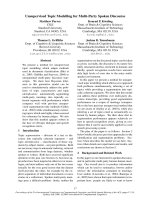
filters and demodulators as shown in Figure 2-1. However, in OFDM, the carriers are
arranged in such a way that the sidebands of the individual carriers overlap as shown
in Figure 2-1 and the signals can still be received without any adjacent carrier
interference. Hence, orthogonal multicarrier modulation technique results in increased
spectrum efficiency [15].
5
Chapter 2 – MB-OFDM UWB Transmitter
Ch. 1 Ch. 2 Ch. 3 Ch. 4 Ch. 5 Ch. 6
(a)
Frequency
Saving of
bandwidth
(b)
Frequency
Figure 2-1: (a) Conventional multicarrier technique, and (b) OFDM technique.
OFDM provides the following advantages over single-carrier modulation:
•
OFDM is an efficient way to deal with multipath.
•
It is possible to enhance the capacity significantly by adapting the data rate per
subcarrier according to the signal-to-noise ratio (SNR) of that particular
subcarrier in relatively slow time-varying channels.
•
OFDM is robust against narrowband interference as only a small percentage of
the subcarriers will be affected by such interferences.
•
OFDM makes single-frequency networks possible.
However, it also has the following drawbacks:
•
OFDM is more sensitive to frequency offset and phase noise.
•
OFDM has a relatively large peak-to-average ratio (PAR), which reduces the
power efficiency of the RF amplifier.
6
Chapter 2 – MB-OFDM UWB Transmitter
2.1.1 Generation of Subcarriers
OFDM signal consists of a sum of subcarriers that are modulated by using schemes
like phase shift keying (PSK) or quadrature amplitude modulation (QAM). The
complex baseband notation of an OFDM symbol starting at t = ts is written as
N2s −1
i
j 2π ( t − t s )
T
∑ d e
s ( t ) = N s i + N2s
i= −
2
0
, ts ≤ t ≤ ts + T
(2.1)
, otherwise
where di are the complex symbols, N s is the number of subcarriers, and T is the
symbol duration.
In (2.1), the real and imaginary parts corresponds to the in-phase (I) and quadrature
(Q) parts of the OFDM signal, which need to be multiplied by a cosine and sine of the
desired carrier frequency to produced the final OFDM signal. The operation of the
OFDM modulator in a block diagram is shown in Figure 2-2.
exp(-jπNs(t-ts)/T)
Data
Serial
To
parallel
OFDM signal
exp(jπ(Ns-2)(t-ts)/T)
Figure 2-2: OFDM modulator.
7
Chapter 2 – MB-OFDM UWB Transmitter
Each subcarrier has exactly an integer number of cycles in the interval T , and the
number of cycles between adjacent subcarriers differs by exactly one. This property
accounts for the orthogonality between the subcarriers. If the j th subcarrier (2.1) is
demodulated by downconverting the signal with a frequency of j T and then
integrating it over time T , the result becomes (2.2). The integration over the
demodulated signal gives the desired output d j + N 2 (multiplied by a constant factor
T ), which is the complex symbol value for the j th carrier. The integration for all
other subcarriers is zero as the frequency difference ( i − j ) T produces an integer
number of cycles within the integration interval T , such that the integration result is
always zero.
∫
t s +T
ts
e
− j 2π
i
( t −ts )
T
s ( t ) dt = ∫
t s +T
ts
=
e
− j 2π
∑
N
i= − s
2
Ns
−1
2
∑d
i= −
Ns
−1
i
( t −ts ) 2
T
Ns
2
i+
Ns
2
∫
t s +T
ts
e
j 2π
d
i+
Ns e
j 2π
i
( t −ts )
T
dt
2
i
( t − ts )
T
dt
(2.2)
= di + N s 2T
The orthogonality of the subcarrier can also be explained in another way. Each
OFDM symbol contains subcarriers that are nonzero over an interval T , so the
spectrum of each symbol is a convolution of a group of Dirac pulses located at the
subcarrier frequencies with the spectrum of a square pulse that is one for a period of
T and zero otherwise. The amplitude spectrum of the square pulse is sinc (π fT ) ,
which has zeros for all frequencies f that are an integer multiple of 1 T . Figure 2-3
8
Chapter 2 – MB-OFDM UWB Transmitter
shows the overlapping sinc spectra of individual subcarriers. At the maximum of each
subcarrier spectrum, the spectra of the rest of the subcarriers are zero. An OFDM
receiver calculates the spectrum values at those points that correspond to the maxima
of individual subcarriers, it can demodulate each subcarrier without any interference
from other subcarriers. As a result, intercarrier interference (ICI), which is crosstalk
between different subcarriers, is avoided.
Figure 2-3: Spectra of subcarriers.
The complex baseband OFDM signal defined in (2.1) is actually the inverse Fourier
transform of N s input symbols. The time discrete equivalent is the inverse discrete
Fourier transform (IDFT), which is given by (2.3). In practice, this transform can be
implemented using inverse fast Fourier transform (IFFT).
s (n) =
N s −1
∑ di e
i =0
9
j 2π
in
N
(2.3)