Development and characterization of multi material printing of the drop on demand (dod) system
Bạn đang xem bản rút gọn của tài liệu. Xem và tải ngay bản đầy đủ của tài liệu tại đây (1.67 MB, 111 trang )
DEVELOPMENT AND CHARACTERIZATION OF
MULTI-MATERIAL PRINTING OF THE
DROP-ON-DEMAND (DOD) SYSTEM
NG JINHHAO
NATIONAL UNIVERSITY OF SINGAPORE
2010
DEVELOPMENT AND CHARACTERIZATION OF
MULTI-MATERIAL PRINTING OF THE
DROP-ON-DEMAND (DOD) SYSTEM
NG JINHHAO
(B.Eng. (Hons.)), NUS
A THESIS SUBMITTED
FOR THE DEGREE OF MASTER OF ENGINEERING
DEPARTMENT OF MECHANICAL ENGINEERING
NATIONAL UNIVERSITY OF SINGAPORE
Acknowledgements
Acknowledgements
The author would like to express his appreciation and gratitude to the following people
for their guidance and advice throughout the course of this project:
•
Prof Jerry Fuh Ying Hsi, Supervisor, National University of Singapore,
Department of Mechanical Engineering, Division of Manufacturing, for his
continuous support and trust.
•
Prof Wong Yoke San, Co-supervisor, National University of Singapore,
Department of Mechanical Engineering, Division of Manufacturing, for his
guidance and advice.
•
Dr Sun Jie, Project Team Supervisor, National University of Singapore,
Department of Mechanical Engineering, Division of Manufacturing, for her
knowledge and patience.
•
Mr. Zhou Jinxin and Mr Li Erqiang, National University of Singapore,
Department of Mechanical Engineering, Division of Manufacturing, for their
assistant and knowledge in carrying out the project.
Last but not least, the author would like to thank the staff of the Advanced Manufacturing
Lab (AML), Workshop 2 (WS2) and the various Laboratories and Workshops of NUS
and their technical staff for their support and technical expertise in overcoming the many
difficulties encountered during the course of the project.
National University of Singapore
i
Table of Contents
Table of Contents
Acknowledgements ......................................................................................................... i
Table of Contents ........................................................................................................... ii
Summary ........................................................................................................................vi
List of Figures ............................................................................................................. viii
List of Tables................................................................................................................ xii
1.
2.
3.
INTROD UCTION ..................................................................................................1
1.1.
Background ......................................................................................................1
1.2.
Challenges .......................................................................................................2
1.3.
Objective ..........................................................................................................4
1.4.
Organization ....................................................................................................4
LITERATURE REVIEW.........................................................................................6
2.1.
Introduction to Inkjet Printing ..........................................................................6
2.2.
Various DOD System and Their Applications ..................................................7
2.3.
Classification of Micro-valve Printing Technique ...........................................11
2.4.
Advantages and Disadvantages of Inkjet Printing ...........................................12
2.4.1.
Advantages of Inkjet Printing ................................................................12
2.4.2.
Problems with Inkjet Printing ................................................................14
OVERVIEW OF A MULTIPLE NOZZLE, MULTIPLE MATERIAL
DISPENSING SYSTEM ............................................................................................... 16
3.1.
Experimental Set-up .......................................................................................16
National University of Singapore
ii
Table of Contents
3.2.
3.2.1.
Synchronizer .........................................................................................17
3.2.2.
Dispenser and Print-Heads .....................................................................18
3.2.3.
Pneumatic System .................................................................................21
3.2.4.
Drivers Hardware and Software .............................................................23
3.2.5.
Visualization System .............................................................................25
3.2.6.
Other General Equipment ......................................................................26
3.3.
4.
Equipment and Materials ................................................................................17
User Interface .................................................................................................27
PREPARATION OF EQUIPMENT FOR PRINTING ........................................... 31
4.1.
Substrate Cleaning Process .............................................................................31
4.1.1.
4.2.
5.
Surface Cleaning ...................................................................................31
Contact Angle Measurement ..........................................................................32
4.2.1.
Procedure for Measurement of Contact Angles ......................................33
4.2.2.
Results and Discussions .........................................................................34
4.2.3.
Conclusion ............................................................................................36
4.3.
Methodology for Optimization of Printing Process .........................................37
4.4.
Dispensing Materials ......................................................................................38
4.5.
Characterization of Micro Valve Dispenser ....................................................40
4.6.
Characterization of Piezo-actuated Dispenser .................................................42
PRINTING (DONE) ON VARIOUS SUBSTRATES ............................................ 45
5.1.
Printing on Brass Substrate.............................................................................45
5.2.
Printing on Glass Substrate.............................................................................47
National University of Singapore
iii
Table of Contents
5.2.1.
Printing of PVP on Glass Substrate and ITO Substrate.............................47
5.2.2.
Printing of PEDOT: PSS on Glass Substrate ............................................49
5.3.
Printing on Photo Paper..................................................................................53
5.3.1.
6.
Printing of PEDOT: PSS and PVP on Photo Paper ..................................54
5.4.
Effects of Curing on Droplets Diameter..........................................................56
5.5.
Effects of Curing on Glass Substrate ..............................................................57
5.5.1.
Printing of PVP on Glass substrate ..........................................................57
5.5.2.
Printing of PEDOT: PSS on Glass substrate.............................................62
5.6.
Effect of Curing on Photo Paper .....................................................................65
5.7.
Printing of Multiple PEDOT: PSS layers ........................................................68
FABRICATION OF MULTIPLE MATERIAL CAPACITOR ON VARIOUS
SUBSTRATES .............................................................................................................. 72
7.
6.1.
Fabrication of Multiple Material Capacitor on Glass Substrate .......................72
6.2.
Fabrication of Multiple Material Capacitors on ITO Substrate ........................74
6.3.
Printing of Multiple Material Capacitor on Photo Paper .................................75
6.4.
Testing and Comparison of Printed Capacitors ...............................................77
6.4.1.
Testing of Printed Capacitor on ITO-Coated Glass Substrate ...................79
6.4.2.
Testing of Printed Capacitor on Photo Paper ............................................82
Conclusion and Recommendations ......................................................................... 86
7.1.
Conclusion .....................................................................................................86
7.1.1.
Development of Multiple Nozzle DoD Inkjet Printing system ................. 86
7.1.2.
Substrate Treatment .................................................................................86
National University of Singapore
iv
Table of Contents
7.1.3.
Characterization of Printing Materials on Various Substrates...................87
7.1.4.
Printing of Multiple Material Capacitor on various Substrates .................88
7.2.
Recommendation ...........................................................................................90
Bibliography.................................................................................................................. 93
Publication .................................................................................................................... 97
National University of Singapore
v
Summary
Summary
In recent years, Inkjet Printing technique has been progressively developed and
improved on in order to meet today’s manufacturing and fabrication demands. Its
application has been widen from conventional graphics printing to other fields from
biomedical to electronic circuitries. Accordingly, printing materials involved are also
explored from dyes and pigments to conductive polymers and biomaterials in order to
fabricate functional structures and circuits. Various dispensers have also been designed
and fabricated to meet the requirements of these new applications. Drop-on-Demand
(DOD) inkjet printing is thought to be one of the promising methods due to the precise
delivered drop volume and controllable drop deposition.
This thesis primarily deal with the possibility of fabricating an applicable multimaterial product through means of the Drop on Demand (DoD) Dispensing System
developed by our project team, using different type of dispensers with different methods
of actuation in a single operation. An attempt is made to develop a frame work for which
the problems and steps involved in fabricating a functional multiple materials component
is documented. Other than compatibility issues and the necessary modifications to the
hardware and software of the original DoD system, much considerations are also given to
the sequence of dispensing for the different dispensers, the use of suitable substrates, the
load bearing capability of the dispensed materials and the different curing time and
temperature for each type of dispensers; all of which can directly or indirectly affect the
performance of the performance of the fabricated multi-material end product. In thesis,
the fabrication of a multiple material capacitor is presented. It consists of multi-layered
National University of Singapore
vi
Summary
conductive polymer and dielectric polymer, printed using parameters and method
established in experiments.
National University of Singapore
vii
List of Figures
List of Figures
Figure 2-1: Schematic of the DoD-IJP process [12] .........................................................8
Figure 2-2: The Biodot system.......................................................................................10
Figure 2-3: Schematics of electrostatic micro-droplet ejector with pole-type nozzle ....... 10
Figure 3-1: A schematic for Multiple Nozzle, Multiple Material Dispensing System ..... 16
Figure 3-2: The synchronizer .........................................................................................18
Figure 3-3: Piezoelectric printhead [24] .........................................................................19
Figure 3-4: Solenoid valve and nozzle for micro-valve dispenser ...................................19
Figure 3-5: Dispensing unit, including adaptors for both print-heads..............................21
Figure 3-6: Vacuum generator .......................................................................................22
Figure 3-7: Pressure regulator for micro valve dispenser ................................................22
Figure 3-8: Microjet Driver and its software interface ....................................................23
Figure 3-9: Software for controlling micro valve dispenser ............................................24
Figure 3-10 : LED array.................................................................................................26
Figure 3-11: CCD Camera for drops observation ...........................................................26
Figure 3-12: Curing unit ................................................................................................26
Figure 3-13: User interface for controlling of parameters during actual printing ............. 28
Figure 3-14: The motion stage used for printing experiments (only 1 print head shown) 28
Figure 3-15: Flow chart for the operation of 2 different print heads in a single operation
..............................................................................................................................29
Figure 4-1: Syringe and plunger system, nozzle tip must be flat and not tapered ............ 34
Figure 4-2: Brass substrate (non treatment) ...................................................................35
National University of Singapore
viii
List of Figures
Figure 4-3: Brass substrate (with treatment) ...................................................................35
Figure 4-4: Glass substrate (non treatment) ....................................................................35
Figure 4-5: Glass substrate (with treatment) ...................................................................35
Figure 4-6: ITO substrate (with treatment) .....................................................................35
Figure 4-7: Drop diameter increases as dispensing pressure increase for 250 µs on-time to
600 µs on-time from 0.4 bar to 1.5 bar ...................................................................41
Figure 4-8: Drop diameter vs Pulse width of Microjet pulse generator ...........................43
Figure 5-1: Individual PVP droplets on brass substrate ..................................................46
Figure 5-2: Drop size of cured PVP droplets on glass slide at on-time 300ms and 0.6bar
dispensing pressure after curing at 70oC .................................................................48
Figure 5-3: PVP lines printed at curing temperature of 70oC ..........................................49
Figure 5-4: The degree at which drops overlap plays an important role the thickness and
uniformity of the resultant line ...............................................................................50
Figure 5-5: Printed PEDOT: PSS lines with varying pitches from 200 micron to 400
micron ...................................................................................................................50
Figure 5-6: One layer of PEDOT: PSS film ...................................................................53
Figure 5-7: Printed PEDOT: PSS lines on photo paper. Crests and troughs are better
defined at larger pitches while lines are more uniform at lower pitches compared to
glass substrate. .......................................................................................................54
Figure 5-8: One layer of PVP.........................................................................................57
Figure 5-9: One layer of PEDOT: PSS ...........................................................................56
Figure 5-10: PVP droplets at 70oC .................................................................................59
Figure 5-11: PVP droplets at 80oC .................................................................................58
National University of Singapore
ix
List of Figures
Figure 5-12: PVP droplets at 88oC .................................................................................58
Figure 5-13: Schematic showing a liquid flow in the evaporation-rate distribution theory
..............................................................................................................................59
Figure 5-14: Clustering of PVP due to hydrophobicity within a confinement of PVP
perimeter ...............................................................................................................61
Figure 5-15: Breaking up of PVP lines into bigger droplets at 60oC ...............................62
Figure 5-16: Drop diameter vs curing temperature, from 25o to 70oC .............................62
Figure 5-17: Smallest average drop size of PEDOT: PSS droplets at 543μm achieved by
195μm nozzle at 80oC ............................................................................................63
Figure 5-18: One layer of PEDOT: PSS film at 700........................................................63
Figure 5-19: 1 layer of PEDOT: PSS film at 60oC..........................................................63
Figure 5-20: 1 layer of PEDOT: PS film at 80oC ............................................................64
Figure 5-21: Drop diameter of PEDOT: PSS at room temperature, 40oC and 60oC
respectively, on a 1mm scale. There is minimal change in drop diameter at all
temperatures shown ...............................................................................................66
Figure 5-22: One layer of PEDOT: PSS at room temperature .........................................66
Figure 5-23: One layer of PEDOT: PSS film at 50oC .....................................................67
Figure 5-24: One layer of PVP film at 50oC curing temperature .....................................67
Figure 5-25: Conductivity of various films of PEDOT: PSS...........................................69
Figure 5-26: One layer film of PEDOT: PSS on the left and 4 layers film on the right ...69
Figure 5-27: Warping film due to non uniform heat distribution in upper and bottom most
layer.......................................................................................................................70
Figure 5-28: Surface roughness of PEDOT: PSS film vs no of film layers .....................71
National University of Singapore
x
List of Figures
Figure 6-1: Break up of PEDOT: PSS from impact of positive air pressure .................... 73
Figure 6-2: A capacitor printed on an ITO substrate. The PEDOT: PSS film is printed on
top of the PVP film ................................................................................................74
Figure 6-3: Two layers of PEDOT: PSS at 300 micron pitch and 60oC curing temperature
..............................................................................................................................76
Figure 6-4: Fabricated capacitor consisting of two layers dielectric PVP in between 2
layers of conductive PEDOT: PSS .........................................................................76
Figure 6-5: Equivalent circuit for parallel and series configuration of LCR hi tester used
for measuring different types of capacitor ..............................................................78
Figure 6-6: Various position of probe of LCR Hi tester on PEDOT: PSS film ................ 79
Figure 6-7: Relationship of capacitance with increasing frequency for ITO substrate ..... 80
Figure 6-8: Graph of capacitance vs frequency for multiple material capacitor printed on
photo paper ............................................................................................................83
Figure 6-9: Impedance and ESR of photo paper printed capacitor as frequency increases
..............................................................................................................................84
National University of Singapore
xi
List of Tables
List of Tables
Table 2-1: Different types of micro-valve in the market today [19] ................................11
Table 3-1: Comparison of print head performance for piezoelectric and micro valve print
head [19]................................................................................................................20
Table 4-1: Measured contact angle for various substrates ...............................................34
Table 5-1: Comparison of theoretical average line thickness with the actual average line
thickness of printed lines with varying pitches. ......................................................52
Table 5-2: Max/min deviations and average line thickness at various pitch for PEDOT:
PSS ........................................................................................................................55
Table 5-3: Max/min deviations and average line thickness at various pitch for PVP....... 55
Table 5-4: Drop diameter of PEDOT: PSS and PVP at room temperature, 40oC and 60oC
respectively. There is minimal change in drop diameter at all temperatures shown . 66
Table 6-1: Capacitance of printed capacitor measured at different points and
corresponding equivalent series resistance (ESR) ...................................................80
Table 6-2: Capacitance of printed capacitor measured at different points and
corresponding equivalent series resistance (ESR) for photo paper ..........................83
National University of Singapore
xii
Chapter 1: Introduction
1. INTRODUCTION
1.1. Background
Rapid Prototyping (RP) is a solid freeform fabrication technique which creates
products using additive manufacturing technology. This technique is different from
traditional manufacturing methods of subtractive manufacturing using CNC machine
tools. Based on the concept of material addition, physical objects are fabricated by
adding materials layer by layer. Computer-aided design (CAD) is usually used in the RP
system to create a 3D model of the object in the first place. The software of the RP
system then convert the 3D model generated from the CAD drawing into a format
compatible with the system. An example would be the STL format that is also adopted in
this project. The 3D model is then converted into 2D data usually by slicing and printed
out layer by layer into a solid physical object. In this manner, RP technology is able to
build complicated shape or geometric features without the use of tools or molds. This
flexible method allows more effective communication between design and manufacturing
and greatly reduces the time required for product development.
Inkjet Printing (IJP) is a data-driven and direct-write additive manufacturing
process. Its advantages includes high resolution with deposition of micro and nanoliter
droplet volumes at high rates, mask-free processing, ease of material handling, micro to
nano scale fabrication, and low cost compared to other fabrication methods. The
operating temperature of this process spans a wide range, from about -110oC to 370oC. A
National University of Singapore
1
Chapter 1: Introduction
high resolution of about 15 to 20µm diameter dispensed droplets can be obtained with
frequencies of about 1Hz to 1MHz. There are generally two types of inkjet printing:
continuous inkjet (CIJ), and drop-on-demand inkjet (DOD). For the DOD method, drops
are only ejected when needed, usually in a certain specified position. All experiments and
fabrications presented in this thesis are done using the DOD method.
Fabrication of polymer devices by Inkjet Printing (IJP), particularly electronic
devices has been gaining much attention in recent years due to the simplicity of
fabrication, low cost and compatibility with a larger range of substrates. IJP has been
shown to fabricate all-polymer transistor [1-4] and polymer light emitted diode (PLED)
[5–7] with much success. Some common printing materials for polymer electronic
devices include polyimide (PI), poly(3,4-ethy-lenedioxythiophene (PEDOT) and poly(4vinyl-phenol) (PVP) among others. Some can be conductive while others are insulative or
dielectric. In this thesis, both kinds of polymer are utilized in the fabrication of the
multiple material capacitors.
1.2. Challenges
One of the challenges of printing a multiple material structure is the compatibility of
the printing materials. In certain cases, where cross-linking of the printing material is
required, for example in the fabrication of scaffold in bio-medical application, the crosslinking agent dispensed from another nozzle is supposed to regulate intermolecular
covalent bonding between polymer chains of the printing material. In other instances,
National University of Singapore
2
Chapter 1: Introduction
mixing of printing materials cannot be allowed to happen to prevent malfunction of the
end product. One example would be printing of electronic devices like capacitors, which
consist of a conductive portion and insulative portion. Care has to be taken to ensure the
conductive material used for printing the top and bottom electrode is completely
separated by the dielectric material in-between.
Another problem that may occur is the different curing time or method required to
cure the layer of printed materials on the substrate. Different material has different curing
time and curing temperature. Some require curing by heat while others may require UV
curing. The droplet sizes from different dispensers are also different, causing curing time
to be different, even if both solvents are the same. Also, when printing multi-layered
structure, we have to make sure that the underlying area is completely cured first before
the next layer is printed. If not the printing materials will tend to mix (but not necessary
form a chemical reaction) and merge into a blob of liquid. This is especially so if both
printing materials uses the same kind of solvent.
Lastly, different materials are only compatible with certain type of dispenser and
mode of dispensing. For example, highly viscous material like sodium alginate is more
suited for positive pressure dispensing by micro valve dispenser while its cross linking
agent, calcium chloride solution, is more suited for negative pressure piezo-actuated
dispensing to prevent breaking up of the underlying layer. Therefore, it is important the
selection of printing materials is compatible with one another and the chosen dispenser.
National University of Singapore
3
Chapter 1: Introduction
1.3. Objective
The main objective is to develop a framework for our multiple nozzle, multiple
material DOD system through which future similar system could be based on.
The main objective will be achieved through the fulfillment of the following tasks, i.e. to:
•
Configure the current software of the DOD system, particularly the user interface,
from a single dispenser one to a multiple dispensers (at least 2) one.
•
Conduct the characterization for the printing materials (PEDOT: PSS and PVP)
on various substrates. This include optimizing the printing parameters for both the
piezo and micro valve dispenser and the curing temperature, among others, for
drop followed by a straight line and lastly a 2D layer for both materials.
•
Fabricate a functional multiple material, multiple layered capacitor using
parameters established in the previously reconfigured DOD system.
1.4. Organization
The content of this thesis is organized as follows:
• Chapter 2 gives an introductory knowledge on the different aspects of Drop-onDemand Inkjet Printing technologies.
National University of Singapore
4
Chapter 1: Introduction
• Chapter 3 gives an overview of the Multiple Nozzle, Multiple Material
Dispensing DoD system, which include the user interface and the experimental
set-up. A description of the experimental equipments and materials will also be
given.
• Chapter 4 describes the preparations of equipments and materials for conducting
of experiments. These include substrates treatment, characterization of print heads
and preparing of printing materials.
• Chapter 5 discusses the printing of different materials on various substrates under
different printing parameters.
• Chapter 6 presents the actual printing of multiple layer, multiple materials
functional electronic devices on various substrates using optimized parameters
from chapter 5.
• Chapter 7 draws conclusions from results that are previously discussed and
analyzed and gives recommendation for which future works can be based on
National University of Singapore
5
Chapter 2: Literature Review
2. LITERATURE REVIEW
2.1. Introduction to Inkjet Printing
Inkjet printing (IJP) is a method of creating an image on a substrate by jetting
droplets of ink or other materials from a small aperture directly and without contact onto
specific or predetermined locations on the substrate in a dot-matrix fashion [8,9]. It has
become a convenient method for transferring electronic data to paper or overhead
transparencies and, due to its low cost, is now present in almost every office and
homes[8]. IJP is a mature and well-developed method in its application to the graphic-arts
industries and is highly successful in this area[9].
The manufacturing industry has, in recent years invested much effort in turning
IJP into a versatile tool for many manufacturing processes[8]. There are now many
applications of IJP in most manufacturing processes where the precise and controlled
deposition of minute quantities of functional materials with specific properties (chemical,
biological or electrical etc) to specific locations on substrates are required[10]. While the
basic principles of droplet formation and fluid dynamics are still relevant, investigation
on these new printing materials like their viscosity, additives, chemistry and thermal
stability is needed in order for industrial applications. Dispensing of polymeric materials
with IJP are now a reality and they have been actively used in producing electronic
devices like all polymer capacitors and transistors.
National University of Singapore
6
Chapter 2: Literature Review
To the knowledge of the author, most IJP DoD systems that utilized multiple print
heads for dispensing usually uses the same type of print head, even though printing
materials and printing parameters can be different. Rarely different types of print heads
with different settings and different mode of operations can be seen in a single printing
process. Combining 2 different print heads or dispensing units with completely different
mode of actuation can allow one to offset the flaws of one kind of print head with the
advantages of the other. This is especially true in fabricating multiple material
components where the chemical structure or physical properties of individual component
are vastly different.
2.2. Various DOD System and Their Applications
There are two primary methods of inkjet printing: continuous inkjet and
drop-on-demand (DOD) inkjet printing. The DOD-IJP can be further subdivided into
piezoelectric and thermal inkjet and electrostatic printing, etc. while continuous inkjet
can be subdivided into the binary deflection and multiple deflection method, among
others. All experiments documented in this thesis utilized DOD-IJP, particularly
piezoelectric printing and positive pressure micro valve printing. A DoD system or
device dispense droplets of materials only when at a specific location on the substrate[11]
that is usually predetermined by the user. The DoD principle eliminates the need for drop
charging and a drop deflection system, as well as do away with the unreliable ink
recirculation system required by Continuous IJP. Currently, most of the industrial and
research interest in IJP are in the DoD methods. Demand mode inkjet technology can
dispense droplets from 150μm to as small as 15μm at rates of between 0 to 25kHz[12].
National University of Singapore
7
Chapter 2: Literature Review
Most DoD systems in the market are using the Thermal or the Piezoelectric principles.
Figure 2-1 shows the droplets dispensed from a DoD-IJP process.
Figure 2-1: Schematic of the DoD-IJP process [12]
There are various kind of DoD systems that are being used in the market or in
research purposes today. However, regardless of the type of transducer that is in use, the
basic principles of the DoD process are similar. One such system is the Piezo-actuated
Drop-on-Demand System. Such systems can be based upon silicon technology.
Dispensing of fluids are usually realized by using actuators to accelerate or displace
droplets usually by sending pulse signals at various frequencies to achieve droplets with
varying dimensions. The main components of a piezo system usually consist of 1) a
pressure chamber for pressure regulation, 2) the actuator for droplets dispensing and 3)
the nozzle itself. The designs for these components will depend on the process that the
systems are used for. The final operating parameters and dimensions will be dependent
on the fluid properties like viscosity, surface tension and density, etc. Also, the design of
the pressure chamber has to be such that bubble formation is avoided during operation.
National University of Singapore
8
Chapter 2: Literature Review
Usually, print heads that utilizes such piezo system are capable of dispensing droplet
volume ranging from 50 pl to 10 nl. [13].
DoD systems can also be pressure driven. In this case, the system relies on
externally applied pressure, for example by a controlled air pressure or syringe pump to
induce flow of fluids or droplets dispensing. One such example is the Pressure-induced
Transfer System [13]. For such systems, a volume of fluid is dispensed according to the
applied pressure. The volume of fluid is connected through a microvalve made of Si
membrane with a pipette tip. When the valve open, the volume of fluid (depending on the
applied pressure) is taken up at the pipette tip, compressed air is then applied to the whole
system through the microvalve to dispense the fluid. The final amount of fluid dispensed
is therefore dependent on the distension of the Si membrane in the microvalve.
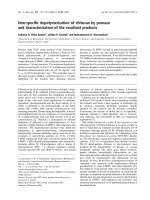
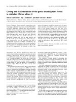
The third type of DoD system that will be introduced in this section is the “Biodot
System” [13]. Here, fluid is dispensed by a pressure from a motorized syringe pump to
the nozzle, which is in turn connected to a reservoir of the same fluid as shown in figure
2-2. The droplets formed at the nozzle are formed by actuating the micro-solenoid valve.
This cut the liquid stream from the syringe into small droplets. Synchronization between
the stepping motor of the syringe pump and the actuation of the micro-solenoid valve
allows for single drop-on-demand displacement. Such a system, while much less complex
and easier to build, is less precise and reliable since bubble formation is possible in the
syringe pump during pumping and at the nozzle.
National University of Singapore
9
Chapter 2: Literature Review
Figure 2-2: The Biodot System
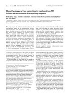
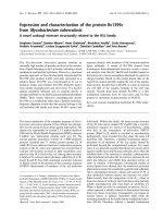
Finally, there is a type of DoD system that utilized electrostatic drop on demand
inkjet print head with a monolithic nozzle. The print head consists of a p-type ground
electrode within the reservoir and a corresponding ring shape electrode around the nozzle
tip as shown in figure 2-3. When a voltage signal is applied to the ring-shaped electrode
plate located against the P-type ground electrode inside the nozzle, an electric field is
Figure 2-3: Schematics of electrostatic micro-droplet ejector with pole-type nozzle
induced between the electrode and the ground. The electrostatic force causes the fluid
meniscus at the nozzle tip to form a micro-droplet. When the electrostatic force is
stronger than the surface tension of the meniscus, the fluid break up and the microdroplet is ejected [14].
National University of Singapore
10
Chapter 2: Literature Review
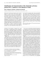
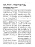
2.3. Classification of Micro-valve Printing Technique
Micro-valves have been used extensively in microfluidic system, particularly in
life science application where handling of biomolecules is required [15-18]. The different
types of micro-valve can be roughly categorized in table 2-1 below. The micro-valves
Table 2-1: Different types of micro-valve in the market today [19]
available in the market today can be categorized into 2 main groups: 1) active and 2)
passive and further sub-divided into a) mechanical, b) non-mechanical and c) externallyactuated. Some types of micro-valves are more suitable for gas flow regulation while
others are used extensively in moving microfluids.
There are also instances where micro-valve is a hybrid of a few categories. For
example, the opening and closing of the valve can be done by using solenoid coil,
National University of Singapore
11