Các ví dụ tính toán tường cừ Larsen
Bạn đang xem bản rút gọn của tài liệu. Xem và tải ngay bản đầy đủ của tài liệu tại đây (1.08 MB, 55 trang )
GEOTECHNICAL DESIGN PROCEDURE
FOR FLEXIBLE WALL SYSTEMS
GEOTECHNICAL DESIGN PROCEDURE
GDP-11
Revision #4
AUGUST 2015
GEOTECHNICAL DESIGN PROCEDURE:
GEOTECHNICAL DESIGN PROCEDURE FOR FLEXIBLE WALL SYSTEMS
GDP-11
Revision #4
STATE OF NEW YORK
DEPARTMENT OF TRANSPORTATION
GEOTECHNICAL ENGINEERING BUREAU
AUGUST 2015
EB 15-025
Page 1 of 19
TABLE OF CONTENTS
I. INTRODUCTION......................................................................................................................4
A. Purpose...........................................................................................................................4
B. General Discussion ........................................................................................................4
C. Soil Parameters ..............................................................................................................4
II. DESIGN PREMISE ...................................................................................................................5
A. Lateral Earth Pressures...................................................................................................5
B. Factor of Safety ..............................................................................................................8
III. FLEXIBLE CANTILEVERED WALLS ...................................................................................9
A. General ...........................................................................................................................9
B. Analysis ..........................................................................................................................9
C. Constructionability.......................................................................................................10
IV. FLEXIBLE ANCHORED WALLS .........................................................................................11
A. General .........................................................................................................................11
B. Analysis ........................................................................................................................11
1. Single Row of Anchors ....................................................................................11
2. Multiple Rows of Anchors ...............................................................................12
C. Anchor Types ...............................................................................................................12
D. Constructability ............................................................................................................13
V. REVIEW REQUIREMENTS ..................................................................................................16
A. General .........................................................................................................................16
B. Flexible Cantilevered Walls .........................................................................................16
C. Flexible Anchored Walls .............................................................................................16
REFERENCES ..............................................................................................................................18
APPENDICIES ..............................................................................................................................19
A. Earth Pressures .......................................................................................................... A-1
Surcharge Loads ........................................................................................................ A-1
Hydrostatic Loads ..................................................................................................... A-1
Inclined Backfill ........................................................................................................ A-2
Inclined Foreslope ..................................................................................................... A-3
Railroad Embankment Zones and Excavation Limits............................................... A-4
B. Recommended Thickness of Wood Lagging .............................................................B-1
C. Earth Pressures for Braced Excavation ......................................................................C-1
Deadman Pressure Distribution & Location Requirements .......................................C-2
EB 15-025
Page 2 of 19
D. Design Guidelines ..................................................................................................... D-1
For Use of the Soldier Pile and Lagging Wall Specifications .................................. D-1
For Selecting a Soldier Pile Section for a Soldier Pile and Lagging Wall
with Rock Sockets..................................................................................................... D-5
For Use of the Sheeting and Excavation Protection System Specifications ........... D-11
For Use of the Grouted Tieback Specifications ...................................................... D-11
For Use of the Steel Ties Specifications ................................................................. D-12
E. Example Problems ..................................................................................................... E-1
Cantilevered Sheeting Wall (US Customary Units) .................................................. E-1
Anchored Sheeting Wall (US Customary Units) ....................................................... E-3
F. Example Problems ..................................................................................................... F-1
Cantilevered Sheeting Wall (International System of Units) ..................................... F-1
Anchored Sheeting Wall (International System of Units) ......................................... F-3
EB 15-025
Page 3 of 19
I. INTRODUCTION
A.
Purpose
The purpose of this document is to provide an acceptable design method and theory for the
geotechnical design of flexible cantilevered or anchored retaining walls to be constructed on New
York State Department of Transportation projects.
The following text provides a general discussion and design guidelines for these flexible wall
systems. This document provides any designer with a framework for progressing a design and an
understanding of the criteria which can be used during a geotechnical review. All structural
aspects of these wall systems shall be performed in accordance with the Department’s accepted
procedures.
B.
General Discussion
Flexible cantilevered or anchored retaining walls are defined in this document to include
temporary or permanent flexible wall systems, or shoring systems, comprised of sheeting or
soldier piles and lagging. An anchored system may include the aforementioned shoring systems
supported by grouted tieback anchors, anchors to a deadman, rakers to a foundation block or
braces or struts to an equivalent or existing wall system or structural element.
Sheeting members of a shoring system are structural units which, when connected one to another,
will form a continuous wall. The wall continuity is usually obtained by interlocking devices
formed as part of the manufactured product. In New York State, the majority of the sheeting used
is made of steel, with timber, vinyl, and concrete used less often.
Soldier piles used as part of a shoring system are structural units, or members, which are spaced
at set intervals. A lagging material is placed between the soldier piles to complete the shoring
system. In New York State, the majority of the soldier piles used are made of steel, with concrete
and timber used less often. The lagging material is usually dependent upon the design life of the
wall. A temporary wall will usually incorporate timber lagging, with steel sheeting as lagging
used less often. A permanent wall will usually incorporate concrete lagging with an architectural
finish.
C.
Soil Parameters
Soil parameters are the design assumptions which characterize the soil type. Typically, designs
are progressed using effective stress parameters to account for long-term stability of the flexible
wall system. For projects in design, the wall designer will be provided the soil parameters to use
in the design of the flexible wall system. For projects in construction, the soil and loading
parameters for the design of the detailed wall are as indicated in the contract plans. If a flexible
wall system is proposed in an area which soil parameters are not listed, the Contractor shall
contact the Engineer, who shall relay the request to the D.C.E.S.
EB 15-025
Page 4 of 19
II. DESIGN PREMISE
A.
Lateral Earth Pressures
A flexible wall system design is required to resist the anticipated lateral pressures without
undergoing significant or excessive lateral deflections. The following list provides an acceptable
geotechnical theory for the development of the lateral earth pressures and potential external loads
and soil backfill configurations which must be accounted for in design:
1.
Earth Pressure Theory:
Use the Rankine Theory for the development of earth pressures on a flexible wall system.
This theory assumes that wall friction (δ) equals zero.
2.
Surcharge Loads:
The term “surcharge” refers to an additional loading on the proposed wall system. This
term usually refers to traffic loading that is in proximity to the wall system. Use the
Spangler Method of analysis (area load of finite length) or Boussinesq Method of analysis
to determine the lateral pressure caused by the surcharge loading. The uniform surcharge
is usually given a value of 250 psf (12 kPa) or an equivalent height of fill. If the designer
knows that heavier construction equipment will be in the vicinity of the wall, the
surcharge loading shall be increased accordingly. A uniform surcharge of at least 250 psf
(12 kPa) is always assumed at the top of a wall that has a level backfill. See Appendix
Page A-1.
For analysis of railroad loadings, refer to “6. Railroad Loading” of this Section.
3.
Hydrostatic Pressure:
The identification of the existing groundwater table is necessary to design for sufficient
support against all possible loadings. Since the locks of sheeting are more or less water
tight when installed and become more watertight as soil is drawn in, water can be trapped
behind the wall causing a head imbalance and greatly increasing the total load. Therefore,
the elevation, or head difference, shall be accounted for in design of the wall system. The
hydrostatic head is the difference between the groundwater elevation and the bottom of
dewatered excavation. See Appendix Page A-1.
4.
Inclined Backfill:
An inclined backfill will induce an additional load on the wall. See Appendix Page A-2.
This situation shall be analyzed by the following:
EB 15-025
Page 5 of 19
Infinite Slope
If the backfill slope remains inclined beyond the limits of the active wedge, the backfill
slope shall be assumed to extend infinitely away from the wall at an angle β. Using this
condition, the Rankine earth pressure is a function of the angle β. To compute horizontal
earth pressures, the resulting earth pressure must be adjusted by the backslope angle.
Subsequent active earth forces are found using these adjusted earth pressures.
Finite Slope
If the backfill slope changes to horizontal within the limits of the active wedge of failure,
the slope may be analyzed in two ways:
5.
A
The broken back slope design (A.R.E.A.) method may be used. This
method is described in Section 5: Retaining Walls in the Standard
Specifications for Highway Bridges, Adopted by the American
Association of State Highway and Transportation Officials
(A.A.S.H.T.O.), Seventeenth Edition.
B
The sloping backfill may be assumed to be equivalent to a horizontal
surcharge loading, located an offset of one-half the distance from the wall
to the slope break. The surcharge loading shall be equivalent to the full
height of the slope.
Inclined Foreslope:
An inclined foreslope, or slope in front of the wall system, will reduce the amount of
passive resistance available to resist loadings. See Appendix Page A-3. This situation
shall be analyzed by the following:
Infinite Slope
If the foreslope extends beyond the passive wedge, the foreslope shall be assumed to
extend infinitely away from the wall at an angle β. Using this condition, the Rankine earth
pressure is a function of the angle β. To compute horizontal earth pressures, the resulting
earth pressure must be adjusted by the foreslope angle. Subsequent passive earth forces
are found using these adjusted earth pressures.
Finite Slope
If the foreslope changes to horizontal within the limits of the passive wedge of failure, the
slope shall be assumed to be finite. In this case, the slope may be analyzed in two ways:
EB 15-025
Page 6 of 19
A.
Infinite slope as noted above.
B.
An excavation to the bottom of the slope.
Engineering judgment shall then be applied when determining which solution to use.
Note in both the infinite and finite slope cases, if the angle β is equal to or greater than the
internal angle of friction of the soil, the excavation shall be assumed to extend down to
the bottom of the slope.
6.
Railroad Loading:
When the proposed excavation requires the support of railroad loads, the designer shall
follow all current applicable railroad requirements. Embankment Zones and Excavation
Restrictions are described in Chapter 23 of the Highway Design Manual. See Appendix
Page A-4.
The system shall be designed to carry E-80 live load consisting of 80 kips axles spaced 5
ft. on centers (356 kN axles spaced 1.5 m on centers). A lower value load can be used if
the railroad indicates, in writing, that the lower value is acceptable for the specific site.
Use the Spangler Method of analysis (area load of infinite length) or the Boussinesq
Method of analysis to determine the lateral pressure caused by the railroad loading. The
load on the track shall be taken as a strip load with a width equal to the length of the ties
(8 ft. 6 in.) (2.6 m). The vertical surcharge caused by each axle shall be equal to the axle
weight divided by the tie length and the axle spacing.
7.
Cohesive Soil:
Due to the variability of the length of time a shoring system is in place, cohesive soils
shall be modeled in the drained condition. These soils shall be modeled as cohesiveless
soils using the drained internal angle of friction. Typically, drained internal angles of
friction for New York State clays range from 22 to 26 (undrained shear strength=0).
EB 15-025
Page 7 of 19
B.
Factor of Safety
A factor of safety (F.S.) shall be applied to the coefficient of passive earth pressure (Kp). The
value for the factor of safety is dependent on the design life of the wall (temporary or permanent).
The passive pressure coefficients (Kp’) used in the design calculations shall be reduced as
follows:
1.
Temporary Retaining Wall:
The factor of safety (F.S.) for a temporary wall is 1.25.
Kp’ = Kp / 1.25.
2.
Permanent Retaining Wall:
The factor of safety (F.S.) for a permanent wall is 1.50.
Kp’ = Kp / 1.50.
EB 15-025
Page 8 of 19
III. FLEXIBLE CANTILEVERED WALLS
A.
General
Sheeting is driven to a depth sufficient for the passive pressure exerted on the embedded portion
to resist the lateral active earth pressures acting on the cantilevered section. To achieve the
required passive earth pressure resistance, embedment depths can often be quite high. Therefore,
due to limitations on the availability of certain section modulus and its associated costs,
cantilevered sheeting walls are usually practical to a maximum height of approximately 15 ft.
(4.6 m).
Soldier piles of a soldier pile and lagging wall system are vertical structural elements spaced at
set intervals, typically 6 ft. to 10 ft. (1.8 m to 3.0 m). A soldier pile and lagging wall also derives
its resistance from the embedded portion of the wall but, because of the higher available section
modulus, greater excavation depths can be supported as compared to those supported by
sheeting. Cantilevered soldier piles are usually practical for excavations up to approximately 20
ft. (6 m) in height.
The minimum timber lagging thickness for a soldier pile and lagging wall should be determined
from the table in Appendix B, taken from Lateral Support Systems and Underpinning, Vol. 1.
Design and Construction, FHWA-RD-75128, April 1976.
Additional design guidance for sheeting and soldier pile and lagging walls is provided and/or
referenced in Appendix D.
B.
Analysis
Use either the Simplified Method or the Conventional Method for the design of a cantilevered
sheeting wall. To account for the differences between the two methods, the calculated depth of
embedment, obtained using the Simplified Method, shall be increased by 20%. This increase is
not a factor of safety. The factor of safety shall be applied to the passive pressure coefficient as
stated in “II. Design Premise: B. Factor of Safety”.
Use either the Simplified Method or the Conventional Method of analysis for the development of
the lateral pressures on a soldier pile and lagging wall. However, as opposed to a sheeting wall
which is analyzed per foot (meter) of wall, the calculations for the design of a soldier pile and
lagging wall must account for the spacing of the individual soldier piles. To determine the active
pressures above the dredgeline, include a factor equivalent to the spacing in the calculations. To
determine the active pressures below the dredgeline, include a factor equivalent to the width of
the soldier pile (for driven piles), or diameter of the hole (for piles installed in excavated holes)
in the calculations. To determine the passive resistance of a soldier pile embedded in soil, assume
that the net passive resistance is mobilized across a maximum of three times the soldier pile
width (for driven piles), or three times the diameter of the hole (for piles installed in excavated
holes).
EB 15-025
Page 9 of 19
Both the Simplified and Conventional Method of analyses are outlined in USS Steel Sheet Piling
Manual. The Simplified Method is also described in Section 5: Retaining Walls in the Standard
Specifications for Highway Bridges, Adopted by the American Association of State Highway and
Transportation Officials (A.A.S.H.T.O.), Seventeenth Edition. The Conventional Method can
also be found in such references as: Foundation Analysis and Design, Fourth Edition by Joseph
E. Bowles and Foundations and Earth Structures by the Department of the Navy, Naval Facilities
Engineering Command, Design Manual 7.2.
C.
Constructability
Prior to the analysis, the designer shall evaluate the site conditions and subsurface profile to
determine which type of flexible wall system is appropriate. Subsurface profiles which include
cobbles, boulders and/or very compact material are sites where sheeting is not recommended and
the designer should investigate alternate wall systems such as soldier piles and lagging. The
designer should also focus on the type and size of equipment that will be needed to install the
wall members. The designer should contemplate the limits of the wall with respect to the existing
site conditions and include the design of any necessary connections. These considerations are
valid for both cantilevered and anchored wall systems.
EB 15-025
Page 10 of 19
IV. FLEXIBLE ANCHORED WALLS
A.
General
When the height of excavation increases over 15 ft. (4.6 m), or if the embedment depth is limited
(for example, the presence of boulders or bedrock), it becomes necessary to investigate the use of
additional support for the wall system. An anchored wall derives its support by the passive
pressure on the front of the embedded portion of the wall and the anchor tie rod near the top of
the wall. Anchored walls are suitable for heights up to approximately 35 ft. (10.5 m).
An additional factor of safety of 1.5 shall be applied to all anchor and brace loads.
Each phase of construction of an anchored wall shall be analyzed. Each phase of construction
affects the lateral earth pressures on the sheeting or soldier piles and therefore, the embedment
and section modulus requirements. Ex.: Phase I: cantilever analysis (excavation to install first
anchor), Phase II: anchored analysis (excavation below first anchor to install second anchor),
Phase III: multiple anchor analysis (excavation below second anchor to install third anchor),
etc...Final Phase: multiple anchor analysis.
Additional design guidance for grouted tiebacks and steel ties is provided and/or referenced in
Appendix D.
B.
Analysis
1.
Single Row of Anchors:
Use the Free Earth Support Method for the design of an anchored sheeting or soldier pile
and lagging wall. The Free Earth Support Method assumes the wall is rigid and may
rotate at the anchor level.
For the design of an anchored soldier pile and lagging wall system, the design must
account for the spacing of the individual soldier piles as stated in “III. Flexible
Cantilevered Walls: B. Analysis”.
The designer shall analyze the effect of any additional vertical or horizontal loads
imposed on the soldier piles or sheeting by the angle (orientation with respect to the wall)
of the anchor. The embedment of sheeting or H-piles (or other sections used as soldier
piles) below the bottom of the excavation should be checked to ensure that it is sufficient
to support the weight of the wall and the vertical component of the tieback force. The
factor of safety should be at least 1.5 based on the design load, assuming resistance to the
vertical load below the bottom of excavation only. Pile and sheeting bearing capacity
should be calculated as shown in the manual on Design and Construction of Driven Pile
Foundations, FHWA-HI-97-013, Rev. November 1998 with Pd and PD equal to the values
on the excavation side of the wall.
EB 15-025
Page 11 of 19
2.
Multiple Row of Anchors:
Use the method of analysis for a braced excavation, based on a rectangular (Terzaghi &
Peck, 1967) or trapezoidal (Terzaghi & Peck, 1948) pressure distribution. The rectangular
pressure distribution is outlined in such references as: Foundation Analysis and Design,
Fourth Edition by Joseph E. Bowles, Principles of Foundation Engineering, Second
Edition by Braja M. Das and in Section 5: Retaining Walls in the Standard Specifications
for Highway Bridges, Adopted by the American Association of State Highway and
Transportation Officials (A.A.S.H.T.O.), Seventeenth Edition. See Appendix Page C-1.
When a rectangular or trapezoidal pressure distribution is used, all of this pressure has to
be resisted by the anchors and by the bending resistance of the sheeting or H-piles. Do
not consider active or passive earth pressure below the bottom of the excavation when
calculating the required anchor loads, unless groundwater level is above the bottom of
excavation. In that case, passive pressure may be used to help resist active earth pressure
and excess hydrostatic pressure. Due consideration should be given to the effect of uplift
on the passive pressure and to the amount of movement required to mobilize full passive
pressure.
For the design of an anchored soldier pile and lagging wall system, the calculations shall
account for the spacing of the individual soldier piles as stated in “III. Flexible
Cantilevered Walls: B. Analysis”.
The designer shall analyze the effect of any additional vertical or horizontal loads
imposed on the soldier piles or sheeting by the angle (orientation with respect to the wall)
of the anchor. The embedment of sheeting or H-piles (or other sections used as soldier
piles) below the bottom of the excavation should be checked to ensure that it is sufficient
to support the weight of the wall and the vertical component of the tieback force. The
factor of safety should be at least 1.5 based on the design load, assuming resistance to the
vertical load below the bottom of excavation only. Pile and sheeting bearing capacity
should be calculated as shown in the manual on Design and Construction of Driven Pile
Foundations, FHWA-HI-97-013, Rev. November 1998 with Pd and PD equal to the values
on the excavation side of the wall.
C.
Anchor Types
The following are possible types of anchor support systems:
1.
Grouted Tiebacks:
A grouted tieback is a system used to transfer tensile loads from the flexible wall to soil
or rock. It consists of all prestressing steel, or tendons, the anchorage, grout, coatings,
sheathings, couplers and encapsulation (if applicable).
EB 15-025
Page 12 of 19
2.
Deadman:
A deadman may consist of large masses of precast or cast-in-place concrete, driven
soldier piles or a continuous sheeting wall. The required depth of the deadman shall be
analyzed based on the active and passive earth pressures exerted on the deadman. See
Appendix Page C-2.
Deadman anchors must be located a distance from the anchored wall such that they can
fully mobilize their passive pressure resistance outside of the anchored wall’s active zone.
This is described in such references as: USS Steel Sheet Piling Manual and Foundation
Analysis and Design, Fourth Edition by Joseph E. Bowles. See Appendix Page C-2.
3.
Struts or Braces / Rakers:
Struts or braces are structural members designed to resist pressure in the direction of their
length. Struts are usually installed to extend from the flexible wall to an adjacent parallel
structure. Rakers are struts that are positioned at an angle extending from the flexible wall
to a foundation block or supporting substructure.
D.
Constructability
Constructability concerns are outlined in “III. Flexible Cantilevered Walls: C. Constructability”.
The following are additional considerations which must be addressed:
1.
General:
The mass stability of the earth-tieback-wall system will be checked by the
Geotechnical Engineering Bureau unless the consultant agreement states that the
consultant will do all the geotechnical design work for the project. The designer
will be notified of any special requirements that have to be included in the
contract to ensure mass stability.
Sheeting Walls:
In the case of permanent anchored sheeting walls (not H-pile and lagging walls
with drainage zones) without special features that would permit water to drain
from behind the wall (weep holes alone are ineffective), the effects of an
unanticipated rise in groundwater level during periods of heavy precipitation
should be considered. Unless detailed groundwater level analyses indicate
otherwise, the final anchor design should be based on a 10 ft. (3 m) rise in the
groundwater level compared to the highest groundwater level determined from
subsurface explorations. To account for possible perched water conditions,
multiply by 1.25 the calculated anchor loads above the groundwater level (after
adding the 10 ft. (3 m) rise).
EB 15-025
Page 13 of 19
Soldier Pile and Lagging Walls:
H-pile (or other type of solider pile) and lagging walls should not be used in
excavations below groundwater level unless the design includes appropriate
positive methods to control seepage.
2.
Grouted Tiebacks:
The presence of existing structures and utilities should be taken into account when
deciding upon the location and inclination of anchors. The installation of the grouted
tieback, location and inclination, should be surveyed against these existing site
constraints. The design shall meet the requirements for minimum ground cover for the
grouted tieback (Recommendations for Prestressed Rock and Soil Anchors, PostTensioning Institute, Fourth Edition: 2004).
The minimum anchor free length is:
a.
15 ft. (4.6 m) or
b.
the length of the tieback from the face of the wall to the theoretical failure plane
plus H/5, whichever is greater.
The theoretical failure plane is inclined at an angle of 45- φ/2 with the vertical, where φ
is the friction angle of the soil, if the backslope is horizontal. For cases where the
backslope is not horizontal, the inclination of the failure plane should be determined from
Foundations and Earth Structures, Design Manual 7-2, NAVFAC DM-7.2, May 1982,
p.7.2-65, or by means of a trial wedge analysis. The point of intersection of the
theoretical failure plane with the face of the wall for walls in non-plastic soils can be
determined as follows:
a.
b.
c.
d.
e.
EB 15-025
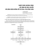
H-pile and lagging wall with single level of anchors: H/10 below the bottom of
the excavation, Fig. 1(a).
Sheeting wall with single level of anchors: Level below bottom of excavation
where moment in sheet pile is zero. Fig. 1(a).
H-pile and lagging wall with more than one level of anchors: Bottom of
excavation, Fig. 1(b).
Sheeting wall with more than one level of anchors and groundwater level below
bottom of excavation: Bottom of excavation, Fig. 1(b).
Sheeting wall with more than one level of anchors and groundwater level above
bottom of excavation: Level below bottom of excavation where moment in
sheeting is zero.
Page 14 of 19
Figure 1 - Location of Theoretical Failure Plane
3.
Deadman:
Both the proposed maintenance and protection of traffic scheme and the construction
sequencing should be evaluated to ensure that there is no interference with the method
and sequence of tie rod installation and its subsequent functioning.
4.
Struts or Braces / Rakers:
The location and spacing of struts or rakers should be critiqued with respect to the
allotted working space and proposed construction. Consideration should be given to
access by workers, supplies and equipment.
The installation of the raker block should be evaluated with respect to the support of the
wall system. The wall should be analyzed for any additional excavation or other
construction impacts necessary to install the raker block.
EB 15-025
Page 15 of 19
V. REVIEW REQUIREMENTS
A.
General
All designs will be reviewed using the analyses and theories stated in this document. All designs
that are part of a construction submittal shall be stamped by a currently registered New York
State Professional Engineer and shall follow the methods described or yield comparable results.
All designs shall be detailed in accordance with the current Departmental guidelines for the
applicable item(s). Copies of these guidelines are available from the Geotechnical Engineering
Bureau.
B.
Flexible Cantilevered Walls
For review of the design of a flexible cantilevered wall, the following information is required:
1. All design assumptions.
2. Cite all reference material. Provide copies of relevant pages of any reference material
that is used in the design and that is not included in the reference list on page 14.
3. Design elevations, including top and toe of sheeting or soldier pile, bottom of
excavation, site specific soil layering and parameters. Cross sections are preferred.
4. Calculations or a computer design for the sheeting or soldier pile and lagging wall
design. If a computer program is used, provide documentation of the assumptions
used in writing the program.
5. Summary of constructability aspects of the proposed design as described in
“III. Flexible Cantilevered Walls: C: Constructability”.
An example design calculation is shown on Appendix Pages E-1 & 2 (US Customary Units) or
Pages F-1 & 2 (International System of Units).
C.
Flexible Anchored Walls
For review of the design of a flexible anchored wall, the following information is required:
1. All design assumptions.
2. Cite all reference material. Provide copies of relevant pages of any reference material
that is used in the design and that is not included in the reference list on page 14.
3. Design elevations, including top and toe of sheeting or soldier pile, bottom of
excavation, location of wales or bracing, deadman/raker block location(s), site
specific soil layering and parameters. Cross sections are preferred.
EB 15-025
Page 16 of 19
4. Calculations or a computer design for the anchored sheeting or soldier pile and
lagging wall design. These calculations shall include each phase of construction. If a
computer program is used, provide documentation of the assumptions used in writing
the program. The design loads for the anchors/braces shall account for the proposed
inclination (if applicable).
5. Calculations for the deadman or raker block design (if applicable).
6. Calculations for the waler design(s) showing connections.
7. For grouted tiebacks, specify proposed free length, inclination and corrosion
protection (if applicable).
8. Summary of constructability aspects of the proposed design as described in
“IV. Flexible Anchored Walls: D. Constructability”.
An example design calculation is shown on Appendix Pages E-3, 4 & 5 (US Customary Units) or
Pages F-3, 4, & 5 (International System of Units).
EB 15-025
Page 17 of 19
REFERENCES
1.
USS Steel Sheet Piling Design Manual, Updated and reprinted by US Department of
Transportation / FHWA with permission: July, 1984.
2.
Foundations and Earth Structures by the Department of the Navy, Naval Facilities
Engineering Command, Design Manual 7.2: May, 1982.
3.
Foundation Analysis and Design, Fourth Edition by Joseph E. Bowles.
4.
Principles of Foundation Engineering, Second Edition by Braja M. Das.
5.
Section 5: Retaining Walls in the Standard Specifications for Highway Bridges, Adopted
by the American Association of State Highway and Transportation Officials
(A.A.S.H.T.O.), Seventeenth Edition, 2002.
6.
Permanent Ground Anchors, FHWA-DP-90-68-003, Demonstration Projects Division:
April, 1990.
7.
Recommendations for Prestressed Rock and Soil Anchors, Post-Tensioning Institute,
Fourth Edition: 2004.
8.
FHWA Report No. FHWA-RD-75-128 Lateral Support Systems and Underpinning, Vol.
I, Final Report April, 1976.
9.
Soil Mechanics in Engineering Practice, 2nd ed., K. Terzaghi and R. B. Peck, 1967, John
Wiley and Sons, New York. The first edition was published in 1948.
10.
Design and Construction of Driven Pile Foundations, FHWA-HI-97-013 Revised
November, 1998.
EB 15-025
Page 18 of 19
APPENDICIES
EB 15-025
Page 19 of 19
Earth Pressures
Surcharge Loads
Hydrostatic Loads
EB 15-025
A-1
Inclined Backfill
Plot the anticipated active failure wedge line against the slope line. If the slope line intersects with the
active failure wedge line, the slope can be considered infinite (Case 1), otherwise the slope can be modeled
by using an equivalent surcharge (Case 2).
EB 15-025
A-2
Inclined Foreslope
Plot the anticipated passive failure wedge line against the slope line. If the slope line intersects with the
passive failure wedge line, the slope can be considered infinite (Case 1), otherwise the slope can be
accounted for by increasing the depth of excavation (Case 2). In the latter case, both methods should be
analyzed and engineering judgment used to determine the solution.
EB 15-025
A-3