Chapter 15 CHEMICAL REACTIONS
Bạn đang xem bản rút gọn của tài liệu. Xem và tải ngay bản đầy đủ của tài liệu tại đây (1.04 MB, 42 trang )
Chapter 15
CHEMICAL REACTIONS
| 751
I
n the preceding chapters we limited our consideration to
nonreacting systems—systems whose chemical composi-
tion remains unchanged during a process. This was the
case even with mixing processes during which a homoge-
neous mixture is formed from two or more fluids without the
occurrence of any chemical reactions. In this chapter, we
specifically deal with systems whose chemical composition
changes during a process, that is, systems that involve chem-
ical reactions.
When dealing with nonreacting systems, we need to con-
sider only the sensible internal energy (associated with tem-
perature and pressure changes) and the latent internal
energy (associated with phase changes). When dealing with
reacting systems, however, we also need to consider the
chemical internal energy, which is the energy associated with
the destruction and formation of chemical bonds between the
atoms. The energy balance relations developed for nonreact-
ing systems are equally applicable to reacting systems, but
the energy terms in the latter case should include the chemi-
cal energy of the system.
In this chapter we focus on a particular type of chemical
reaction, known as combustion, because of its importance in
engineering. But the reader should keep in mind, however,
that the principles developed are equally applicable to other
chemical reactions.
We start this chapter with a general discussion of fuels and
combustion. Then we apply the mass and energy balances to
reacting systems. In this regard we discuss the adiabatic
flame temperature, which is the highest temperature a react-
ing mixture can attain. Finally, we examine the second-law
aspects of chemical reactions.
Objectives
The objectives of Chapter 15 are to:
• Give an overview of fuels and combustion.
• Apply the conservation of mass to reacting systems to
determine balanced reaction equations.
• Define the parameters used in combustion analysis, such
as air–fuel ratio, percent theoretical air, and dew-point
temperature.
• Apply energy balances to reacting systems for both steady-
flow control volumes and fixed mass systems.
• Calculate the enthalpy of reaction, enthalpy of combustion,
and the heating values of fuels.
• Determine the adiabatic flame temperature for reacting
mixtures.
• Evaluate the entropy change of reacting systems.
• Analyze reacting systems from the second-law perspective.
cen84959_ch15.qxd 4/20/05 3:23 PM Page 751
15–1
FUELS AND COMBUSTION
Any material that can be burned to release thermal energy is called a fuel.
Most familiar fuels consist primarily of hydrogen and carbon. They are
called hydrocarbon fuels and are denoted by the general formula C
n
H
m
.
Hydrocarbon fuels exist in all phases, some examples being coal, gasoline,
and natural gas.
The main constituent of coal is carbon. Coal also contains varying
amounts of oxygen, hydrogen, nitrogen, sulfur, moisture, and ash. It is diffi-
cult to give an exact mass analysis for coal since its composition varies
considerably from one geographical area to the next and even within the
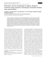
same geographical location. Most liquid hydrocarbon fuels are a mixture
of numerous hydrocarbons and are obtained from crude oil by distillation
(Fig. 15–1). The most volatile hydrocarbons vaporize first, forming what we
know as gasoline. The less volatile fuels obtained during distillation are
kerosene, diesel fuel, and fuel oil. The composition of a particular fuel
depends on the source of the crude oil as well as on the refinery.
Although liquid hydrocarbon fuels are mixtures of many different hydro-
carbons, they are usually considered to be a single hydrocarbon for conve-
nience. For example, gasoline is treated as octane, C
8
H
18
, and the diesel
fuel as dodecane, C
12
H
26
. Another common liquid hydrocarbon fuel is
methyl alcohol, CH
3
OH, which is also called methanol and is used in some
gasoline blends. The gaseous hydrocarbon fuel natural gas, which is a mix-
ture of methane and smaller amounts of other gases, is often treated as
methane, CH
4
, for simplicity.
Natural gas is produced from gas wells or oil wells rich in natural gas. It
is composed mainly of methane, but it also contains small amounts of
ethane, propane, hydrogen, helium, carbon dioxide, nitrogen, hydrogen sul-
fate, and water vapor. On vehicles, it is stored either in the gas phase at
pressures of 150 to 250 atm as CNG (compressed natural gas), or in the liq-
uid phase at Ϫ162°C as LNG (liquefied natural gas). Over a million vehi-
cles in the world, mostly buses, run on natural gas. Liquefied petroleum gas
(LPG) is a byproduct of natural gas processing or the crude oil refining. It
consists mainly of propane and thus LPG is usually referred to as propane.
However, it also contains varying amounts of butane, propylene, and
butylenes. Propane is commonly used in fleet vehicles, taxis, school buses,
and private cars. Ethanol is obtained from corn, grains, and organic waste.
Methonal is produced mostly from natural gas, but it can also be obtained
from coal and biomass. Both alcohols are commonly used as additives in
oxygenated gasoline and reformulated fuels to reduce air pollution.
Vehicles are a major source of air pollutants such as nitric oxides, carbon
monoxide, and hydrocarbons, as well as the greenhouse gas carbon dioxide,
and thus there is a growing shift in the transportation industry from the tra-
ditional petroleum-based fuels such as gaoline and diesel fuel to the cleaner
burning alternative fuels friendlier to the environment such as natural gas,
alcohols (ethanol and methanol), liquefied petroleum gas (LPG), and
hydrogen. The use of electric and hybrid cars is also on the rise. A compari-
son of some alternative fuels for transportation to gasoline is given in Table
15–1. Note that the energy contents of alternative fuels per unit volume are
lower than that of gasoline or diesel fuel, and thus the driving range of a
752 | Thermodynamics
Gasoline
Kerosene
Diesel fuel
Fuel oil
CRUDE
OIL
FIGURE 15–1
Most liquid hydrocarbon fuels are
obtained from crude oil by distillation.
cen84959_ch15.qxd 4/20/05 3:23 PM Page 752
vehicle on a full tank is lower when running on an alternative fuel. Also,
when comparing cost, a realistic measure is the cost per unit energy rather
than cost per unit volume. For example, methanol at a unit cost of $1.20/L
may appear cheaper than gasoline at $1.80/L, but this is not the case since
the cost of 10,000 kJ of energy is $0.57 for gasoline and $0.66 for
methanol.
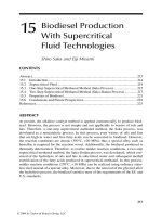
A chemical reaction during which a fuel is oxidized and a large quantity
of energy is released is called combustion (Fig. 15–2). The oxidizer most
often used in combustion processes is air, for obvious reasons—it is free
and readily available. Pure oxygen O
2
is used as an oxidizer only in some
specialized applications, such as cutting and welding, where air cannot be
used. Therefore, a few words about the composition of air are in order.
On a mole or a volume basis, dry air is composed of 20.9 percent oxygen,
78.1 percent nitrogen, 0.9 percent argon, and small amounts of carbon diox-
ide, helium, neon, and hydrogen. In the analysis of combustion processes,
the argon in the air is treated as nitrogen, and the gases that exist in trace
amounts are disregarded. Then dry air can be approximated as 21 percent
oxygen and 79 percent nitrogen by mole numbers. Therefore, each mole of
oxygen entering a combustion chamber is accompanied by 0.79/0.21 ϭ 3.76
mol of nitrogen (Fig. 15–3). That is,
(15–1)
During combustion, nitrogen behaves as an inert gas and does not react with
other elements, other than forming a very small amount of nitric oxides.
However, even then the presence of nitrogen greatly affects the outcome of
a combustion process since nitrogen usually enters a combustion chamber in
large quantities at low temperatures and exits at considerably higher tempera-
tures, absorbing a large proportion of the chemical energy released during
combustion. Throughout this chapter, nitrogen is assumed to remain perfectly
1 kmol O
2
ϩ 3.76 kmol N
2
ϭ 4.76 kmol air
Chapter 15 | 753
FIGURE 15–2
Combustion is a chemical reaction
during which a fuel is oxidized and a
large quantity of energy is released.
© Reprinted with special permission of King
Features Syndicate.
AIR
AIR
( )
( )
21% O
21% O
2
79% N
79% N
2
1 kmol O
1 kmol O
2
3.76 kmol N
3.76 kmol N
2
FIGURE 15–3
Each kmol of O
2
in air is accompanied
by 3.76 kmol of N
2
.
TABLE 15–1
A comparison of some alternative fuels to the traditional petroleum-based fuels
used in transportation
Energy content Gasoline equivalence,*
Fuel kJ/L L/L-gasoline
Gasoline 31,850 1
Light diesel 33,170 0.96
Heavy diesel 35,800 0.89
LPG (Liquefied petroleum gas,
primarily propane) 23,410 1.36
Ethanol (or ethyl alcohol) 29,420 1.08
Methanol (or methyl alcohol) 18,210 1.75
CNG (Compressed natural gas,
primarily methane, at 200 atm) 8,080 3.94
LNG (Liquefied natural gas,
primarily methane) 20,490 1.55
*Amount of fuel whose energy content is equal to the energy content of 1-L gasoline.
cen84959_ch15.qxd 4/27/05 10:55 AM Page 753
inert. Keep in mind, however, that at very high temperatures, such as those
encountered in internal combustion engines, a small fraction of nitrogen
reacts with oxygen, forming hazardous gases such as nitric oxide.
Air that enters a combustion chamber normally contains some water
vapor (or moisture), which also deserves consideration. For most combus-
tion processes, the moisture in the air and the H
2
O that forms during com-
bustion can also be treated as an inert gas, like nitrogen. At very high
temperatures, however, some water vapor dissociates into H
2
and O
2
as well
as into H, O, and OH. When the combustion gases are cooled below the
dew-point temperature of the water vapor, some moisture condenses. It is
important to be able to predict the dew-point temperature since the water
droplets often combine with the sulfur dioxide that may be present in the
combustion gases, forming sulfuric acid, which is highly corrosive.
During a combustion process, the components that exist before the reac-
tion are called reactants and the components that exist after the reaction are
called products (Fig. 15–4). Consider, for example, the combustion of
1 kmol of carbon with 1 kmol of pure oxygen, forming carbon dioxide,
(15–2)
Here C and O
2
are the reactants since they exist before combustion, and
CO
2
is the product since it exists after combustion. Note that a reactant does
not have to react chemically in the combustion chamber. For example, if
carbon is burned with air instead of pure oxygen, both sides of the combus-
tion equation will include N
2
. That is, the N
2
will appear both as a reactant
and as a product.
We should also mention that bringing a fuel into intimate contact with
oxygen is not sufficient to start a combustion process. (Thank goodness it is
not. Otherwise, the whole world would be on fire now.) The fuel must be
brought above its ignition temperature to start the combustion. The mini-
mum ignition temperatures of various substances in atmospheric air are
approximately 260°C for gasoline, 400°C for carbon, 580°C for hydrogen,
610°C for carbon monoxide, and 630°C for methane. Moreover, the propor-
tions of the fuel and air must be in the proper range for combustion to
begin. For example, natural gas does not burn in air in concentrations less
than 5 percent or greater than about 15 percent.
As you may recall from your chemistry courses, chemical equations are
balanced on the basis of the conservation of mass principle (or the mass
balance), which can be stated as follows: The total mass of each element is
conserved during a chemical reaction (Fig. 15–5). That is, the total mass of
each element on the right-hand side of the reaction equation (the products)
must be equal to the total mass of that element on the left-hand side (the
reactants) even though the elements exist in different chemical compounds
in the reactants and products. Also, the total number of atoms of each ele-
ment is conserved during a chemical reaction since the total number of
atoms is equal to the total mass of the element divided by its atomic mass.
For example, both sides of Eq. 15–2 contain 12 kg of carbon and 32 kg of
oxygen, even though the carbon and the oxygen exist as elements in the
reactants and as a compound in the product. Also, the total mass of reactants
is equal to the total mass of products, each being 44 kg. (It is common
practice to round the molar masses to the nearest integer if great accuracy is
C ϩ O
2
S CO
2
754 | Thermodynamics
Reaction
chamber
Reactants
Products
FIGURE 15–4
In a steady-flow combustion process,
the components that enter the reaction
chamber are called reactants and the
components that exit are called
products.
H
2
ϩ
2
2 kg hydrogen
2 kg hydrogen
16 kg oxygen
16 kg oxygen
2 kg hydrogen
2 kg hydrogen
16 kg oxygen
16 kg oxygen
1
O
2
→ H
2
O
FIGURE 15–5
The mass (and number of atoms) of
each element is conserved during a
chemical reaction.
cen84959_ch15.qxd 4/20/05 3:23 PM Page 754
EXAMPLE 15–1 Balancing the Combustion Equation
One kmol of octane (C
8
H
18
) is burned with air that contains 20 kmol of O
2
,
as shown in Fig. 15–7. Assuming the products contain only CO
2
, H
2
O, O
2
,
and N
2
, determine the mole number of each gas in the products and the
air–fuel ratio for this combustion process.
Solution The amount of fuel and the amount of oxygen in the air are given.
The amount of the products and the AF are to be determined.
Assumptions The combustion products contain CO
2
, H
2
O, O
2
, and N
2
only.
Properties The molar mass of air is M
air
ϭ 28.97 kg/kmol Х 29.0 kg/kmol
(Table A–1).
Analysis The chemical equation for this combustion process can be written as
where the terms in the parentheses represent the composition of dry air that
contains 1 kmol of O
2
and x, y, z, and w represent the unknown mole num-
bers of the gases in the products. These unknowns are determined by apply-
ing the mass balance to each of the elements—that is, by requiring that the
total mass or mole number of each element in the reactants be equal to that
in the products:
C:
H:
O:
N
2
:
Substituting yields
Note that the coefficient 20 in the balanced equation above represents the
number of moles of oxygen, not the number of moles of air. The latter is
obtained by adding 20 ϫ 3.76 ϭ 75.2 moles of nitrogen to the 20 moles of
C
8
H
18
ϩ 201O
2
ϩ 3.76N
2
2 S 8CO
2
ϩ 9H
2
O ϩ 7.5O
2
ϩ 75.2N
2
120 213.762 ϭ w
¬
S
¬
w ϭ 75.2
20 ϫ 2 ϭ 2x ϩ y ϩ 2z
¬
S
¬
z ϭ 7.5
18 ϭ 2y
¬
S
¬
y ϭ 9
8 ϭ x
¬
S
¬
x ϭ 8
C
8
H
18
ϩ 20 1O
2
ϩ 3.76N
2
2 S xCO
2
ϩ yH
2
O ϩ zO
2
ϩ wN
2
not required.) However, notice that the total mole number of the reactants
(2 kmol) is not equal to the total mole number of the products (1 kmol). That
is, the total number of moles is not conserved during a chemical reaction.
A frequently used quantity in the analysis of combustion processes to
quantify the amounts of fuel and air is the air–fuel ratio AF. It is usually
expressed on a mass basis and is defined as the ratio of the mass of air to
the mass of fuel for a combustion process (Fig. 15–6). That is,
(15–3)
The mass m of a substance is related to the number of moles N through the
relation m ϭ NM, where M is the molar mass.
The air–fuel ratio can also be expressed on a mole basis as the ratio of the
mole numbers of air to the mole numbers of fuel. But we will use the for-
mer definition. The reciprocal of air–fuel ratio is called the fuel–air ratio.
AF ϭ
m
air
m
fuel
Chapter 15 | 755
Combustion
chamber
Air
Products
AF = 17
17 kg
Fuel
1 kg
18 kg
FIGURE 15–6
The air–fuel ratio (AF) represents the
amount of air used per unit mass of
fuel during a combustion process.
Combustion
chamber
AIR
C
8
H
18
1 kmol
x CO
2
y H
2
O
z O
2
w N
2
FIGURE 15–7
Schematic for Example 15–1.
cen84959_ch15.qxd 4/20/05 3:23 PM Page 755
15–2
THEORETICAL AND ACTUAL
COMBUSTION PROCESSES
It is often instructive to study the combustion of a fuel by assuming that the
combustion is complete. A combustion process is complete if all the carbon
in the fuel burns to CO
2
, all the hydrogen burns to H
2
O, and all the sulfur (if
any) burns to SO
2
. That is, all the combustible components of a fuel are
burned to completion during a complete combustion process (Fig. 15–8).
Conversely, the combustion process is incomplete if the combustion prod-
ucts contain any unburned fuel or components such as C, H
2
, CO, or OH.
Insufficient oxygen is an obvious reason for incomplete combustion, but it
is not the only one. Incomplete combustion occurs even when more oxygen
is present in the combustion chamber than is needed for complete combus-
tion. This may be attributed to insufficient mixing in the combustion cham-
ber during the limited time that the fuel and the oxygen are in contact.
Another cause of incomplete combustion is dissociation, which becomes
important at high temperatures.
Oxygen has a much greater tendency to combine with hydrogen than it
does with carbon. Therefore, the hydrogen in the fuel normally burns to
completion, forming H
2
O, even when there is less oxygen than needed for
complete combustion. Some of the carbon, however, ends up as CO or just
as plain C particles (soot) in the products.
The minimum amount of air needed for the complete combustion of a fuel
is called the stoichiometric or theoretical air. Thus, when a fuel is com-
pletely burned with theoretical air, no uncombined oxygen is present in the
product gases. The theoretical air is also referred to as the chemically cor-
rect amount of air, or 100 percent theoretical air. A combustion process
with less than the theoretical air is bound to be incomplete. The ideal com-
bustion process during which a fuel is burned completely with theoretical
air is called the stoichiometric or theoretical combustion of that fuel (Fig.
15–9). For example, the theoretical combustion of methane is
Notice that the products of the theoretical combustion contain no unburned
methane and no C, H
2
, CO, OH, or free O
2
.
CH
4
ϩ 2 1O
2
ϩ 3.76N
2
2 S CO
2
ϩ 2H
2
O ϩ 7.52N
2
756 | Thermodynamics
oxygen, giving a total of 95.2 moles of air. The air–fuel ratio (AF) is deter-
mined from Eq. 15–3 by taking the ratio of the mass of the air and the mass
of the fuel,
That is, 24.2 kg of air is used to burn each kilogram of fuel during this
combustion process.
ϭ 24.2 kg air
/
kg fuel
ϭ
120 ϫ 4.76 kmol2129 kg>kmol2
18 kmol 2112 kg>kmol 2 ϩ 19 kmol 212 kg>kmol 2
AF ϭ
m
air
m
fuel
ϭ
1NM 2
air
1NM 2
C
ϩ 1NM 2
H
2
CH
4
+ 2(O
2
+ 3.76N
2
) →
• no unburned fuel
• no free oxygen in products
CO
2
+ 2H
2
O + 7.52N
2
FIGURE 15–9
The complete combustion process
with no free oxygen in the products is
called theoretical combustion.
Combustion
chamber
AIR
C
n
H
m
Fuel
n CO
2
m
H
2
O
Excess O
2
N
2
2
FIGURE 15–8
A combustion process is complete if
all the combustible components of the
fuel are burned to completion.
cen84959_ch15.qxd 4/20/05 3:23 PM Page 756
In actual combustion processes, it is common practice to use more air
than the stoichiometric amount to increase the chances of complete combus-
tion or to control the temperature of the combustion chamber. The amount
of air in excess of the stoichiometric amount is called excess air. The
amount of excess air is usually expressed in terms of the stoichiometric air
as percent excess air or percent theoretical air. For example, 50 percent
excess air is equivalent to 150 percent theoretical air, and 200 percent
excess air is equivalent to 300 percent theoretical air. Of course, the stoi-
chiometric air can be expressed as 0 percent excess air or 100 percent theo-
retical air. Amounts of air less than the stoichiometric amount are called
deficiency of air and are often expressed as percent deficiency of air. For
example, 90 percent theoretical air is equivalent to 10 percent deficiency of
air. The amount of air used in combustion processes is also expressed in
terms of the equivalence ratio, which is the ratio of the actual fuel–air ratio
to the stoichiometric fuel–air ratio.
Predicting the composition of the products is relatively easy when the
combustion process is assumed to be complete and the exact amounts of the
fuel and air used are known. All one needs to do in this case is simply apply
the mass balance to each element that appears in the combustion equation,
without needing to take any measurements. Things are not so simple, how-
ever, when one is dealing with actual combustion processes. For one thing,
actual combustion processes are hardly ever complete, even in the presence
of excess air. Therefore, it is impossible to predict the composition of the
products on the basis of the mass balance alone. Then the only alternative we
have is to measure the amount of each component in the products directly.
A commonly used device to analyze the composition of combustion gases
is the Orsat gas analyzer. In this device, a sample of the combustion gases
is collected and cooled to room temperature and pressure, at which point its
volume is measured. The sample is then brought into contact with a chemi-
cal that absorbs the CO
2
. The remaining gases are returned to the room tem-
perature and pressure, and the new volume they occupy is measured. The
ratio of the reduction in volume to the original volume is the volume frac-
tion of the CO
2
, which is equivalent to the mole fraction if ideal-gas behav-
ior is assumed (Fig. 15–10). The volume fractions of the other gases are
determined by repeating this procedure. In Orsat analysis the gas sample is
collected over water and is maintained saturated at all times. Therefore, the
vapor pressure of water remains constant during the entire test. For this rea-
son the presence of water vapor in the test chamber is ignored and data are
reported on a dry basis. However, the amount of H
2
O formed during com-
bustion is easily determined by balancing the combustion equation.
Chapter 15 | 757
EXAMPLE 15–2 Dew-Point Temperature of Combustion Products
Ethane (C
2
H
6
) is burned with 20 percent excess air during a combustion
process, as shown in Fig. 15–11. Assuming complete combustion and a total
pressure of 100 kPa, determine (a) the air–fuel ratio and (b) the dew-point
temperature of the products.
Solution The fuel is burned completely with excess air. The AF and the
dew point of the products are to be determined.
BEFORE
AFTER
100 kPa
25°C
Gas sample
including CO
2
1 liter
100 kPa
25°C
Gas sample
without CO
2
0.9 liter
y
CO
2
=
V
CO
2
V
0.1
1
= = 0.1
FIGURE 15–10
Determining the mole fraction of the
CO
2
in combustion gases by using the
Orsat gas analyzer.
Combustion
chamber
AIR
C
2
H
6
CO
2
H
2
O
O
2
N
2
(20% excess)
100 kPa
FIGURE 15–11
Schematic for Example 15–2.
cen84959_ch15.qxd 4/20/05 3:23 PM Page 757
758 | Thermodynamics
Assumptions 1 Combustion is complete. 2 Combustion gases are ideal gases.
Analysis The combustion products contain CO
2
, H
2
O, N
2
, and some excess
O
2
only. Then the combustion equation can be written as
where a
th
is the stoichiometric coefficient for air. We have automatically
accounted for the 20 percent excess air by using the factor 1.2a
th
instead of a
th
for air. The stoichiometric amount of oxygen (a
th
O
2
) is used to oxidize the fuel,
and the remaining excess amount (0.2a
th
O
2
) appears in the products as unused
oxygen. Notice that the coefficient of N
2
is the same on both sides of the equa-
tion, and that we wrote the C and H balances directly since they are so obvi-
ous. The coefficient a
th
is determined from the O
2
balance to be
Substituting,
(a) The air–fuel ratio is determined from Eq. 15–3 by taking the ratio of the
mass of the air to the mass of the fuel,
That is, 19.3 kg of air is supplied for each kilogram of fuel during this com-
bustion process.
(b) The dew-point temperature of the products is the temperature at which
the water vapor in the products starts to condense as the products are
cooled at constant pressure. Recall from Chap. 14 that the dew-point tem-
perature of a gas–vapor mixture is the saturation temperature of the water
vapor corresponding to its partial pressure. Therefore, we need to determine
the partial pressure of the water vapor P
v
in the products first. Assuming
ideal-gas behavior for the combustion gases, we have
Thus,
(Table A–5)
T
dp
ϭ T
sat @ 13.96 kPa
ϭ 52.3°C
P
v
ϭ a
N
v
N
prod
b1P
prod
2 ϭ a
3 kmol
21.49 kmol
b1100 kPa2 ϭ 13.96 kPa
ϭ 19.3 kg air
/
kg fuel
AF ϭ
m
air
m
fuel
ϭ
14.2 ϫ 4.76 kmol2129 kg>kmol2
12 kmol 2112 kg>kmol 2 ϩ 13 kmol 212 kg>kmol 2
C
2
H
6
ϩ 4.2 1O
2
ϩ 3.76N
2
2 S 2CO
2
ϩ 3H
2
O ϩ 0.7O
2
ϩ 15.79N
2
O
2
:
¬¬
1.2a
th
ϭ 2 ϩ 1.5 ϩ 0.2a
th
S a
th
ϭ 3.5
C
2
H
6
ϩ 1.2a
th
1O
2
ϩ 3.76N
2
2 S 2CO
2
ϩ 3H
2
O ϩ 0.2a
th
O
2
ϩ 11.2 ϫ 3.762a
th
N
2
EXAMPLE 15–3 Combustion of a Gaseous Fuel with Moist Air
A certain natural gas has the following volumetric analysis: 72 percent CH
4
,
9 percent H
2
, 14 percent N
2
, 2 percent O
2
, and 3 percent CO
2
. This gas is
now burned with the stoichiometric amount of air that enters the combustion
chamber at 20°C, 1 atm, and 80 percent relative humidity, as shown in
Fig. 15–12. Assuming complete combustion and a total pressure of 1 atm,
determine the dew-point temperature of the products.
Solution A gaseous fuel is burned with the stoichiometric amount of moist
air. The dew point temperature of the products is to be determined.
Combustion
chamber
AIR
FUEL
CO
2
H
2
O
N
2
20°C, = 80%
φ
1 atm
CH
4
, O
2
, H
2
,
N
2
, CO
2
FIGURE 15–12
Schematic for Example 15–3.
cen84959_ch15.qxd 4/20/05 3:23 PM Page 758
Chapter 15 | 759
Assumptions 1 The fuel is burned completely and thus all the carbon in the
fuel burns to CO
2
and all the hydrogen to H
2
O. 2 The fuel is burned with the
stoichiometric amount of air and thus there is no free O
2
in the product
gases. 3 Combustion gases are ideal gases.
Properties The saturation pressure of water at 20°C is 2.3392 kPa (Table A–4).
Analysis We note that the moisture in the air does not react with anything;
it simply shows up as additional H
2
O in the products. Therefore, for simplic-
ity, we balance the combustion equation by using dry air and then add the
moisture later to both sides of the equation.
Considering 1 kmol of fuel,
fuel dry air
The unknown coefficients in the above equation are determined from mass
balances on various elements,
C:
H:
O
2
:
N
2
:
Next we determine the amount of moisture that accompanies 4.76a
th
ϭ
(4.76)(1.465) ϭ 6.97 kmol of dry air. The partial pressure of the moisture
in the air is
Assuming ideal-gas behavior, the number of moles of the moisture in the
air is
which yields
The balanced combustion equation is obtained by substituting the coeffi-
cients determined earlier and adding 0.131 kmol of H
2
O to both sides of the
equation:
fuel dry air
moisture includes moisture
The dew-point temperature of the products is the temperature at which
the water vapor in the products starts to condense as the products are cooled.
Again, assuming ideal-gas behavior, the partial pressure of the water vapor in
the combustion gases is
P
v,prod
ϭ a
N
v,prod
N
prod
bP
prod
ϭ a
1.661 kmol
8.059 kmol
b1101.325 kPa2 ϭ 20.88 kPa
ϩ 0.131H
2
O S 0.75CO
2
ϩ 1.661H
2
O ϩ 5.648N
2
10.72CH
4
ϩ 0.09H
2
ϩ 0.14N
2
ϩ 0.02O
2
ϩ 0.03CO
2
2
ϩ 1.465 1O
2
ϩ 3.76N
2
2
N
v,air
ϭ 0.131 kmol
N
v,air
ϭ a
P
v,air
P
total
b N
total
ϭ a
1.871 kPa
101.325 kPa
b16.97 ϩ N
v,air
2
P
v,air
ϭ f
air
P
sat @ 20°C
ϭ 10.80 212.3392 kPa2 ϭ 1.871 kPa
0.14 ϩ 3.76a
th
ϭ z
¬
S
¬
z ϭ 5.648
0.02 ϩ 0.03 ϩ a
th
ϭ x ϩ
y
2
¬
S
¬
a
th
ϭ 1.465
0.72 ϫ 4 ϩ 0.09 ϫ 2 ϭ 2y
¬
S
¬
y ϭ 1.53
0.72 ϩ 0.03 ϭ x
¬
S
¬
x ϭ 0.75
xCO
2
ϩ yH
2
O ϩ zN
2
10.72CH
4
ϩ 0.09H
2
ϩ 0.14N
2
ϩ 0.02O
2
ϩ 0.03CO
2
2
¬
ϩ a
th
1O
2
ϩ 3.76N
2
2 S
1555555555555552555555555555553
155525553
155555555555552555555555555553
1555255553
14243
14243
cen84959_ch15.qxd 4/20/05 3:23 PM Page 759
760 | Thermodynamics
Thus,
Discussion If the combustion process were achieved with dry air instead of
moist air, the products would contain less moisture, and the dew-point tem-
perature in this case would be 59.5°C.
T
dp
ϭ T
sat @ 20.88 kPa
ϭ 60.9°C
EXAMPLE 15–4 Reverse Combustion Analysis
Octane (C
8
H
18
) is burned with dry air. The volumetric analysis of the prod-
ucts on a dry basis is (Fig. 15–13)
CO
2
: 10.02 percent
O
2
: 5.62 percent
CO: 0.88 percent
N
2
: 83.48 percent
Determine (a) the air–fuel ratio, (b) the percentage of theoretical air used,
and (c) the amount of H
2
O that condenses as the products are cooled to
25°C at 100 kPa.
Solution Combustion products whose composition is given are cooled to
25°C. The AF, the percent theoretical air used, and the fraction of water
vapor that condenses are to be determined.
Assumptions Combustion gases are ideal gases.
Properties The saturation pressure of water at 25°C is 3.1698 kPa (Table A–4).
Analysis Note that we know the relative composition of the products, but
we do not know how much fuel or air is used during the combustion process.
However, they can be determined from mass balances. The H
2
O in the com-
bustion gases will start condensing when the temperature drops to the dew-
point temperature.
For ideal gases, the volume fractions are equivalent to the mole fractions.
Considering 100 kmol of dry products for convenience, the combustion
equation can be written as
The unknown coefficients x, a, and b are determined from mass balances,
N
2
:
C:
H:
O
2
:
The O
2
balance is not necessary, but it can be used to check the values
obtained from the other mass balances, as we did previously. Substituting,
we get
10.02CO
2
ϩ 0.88CO ϩ 5.62O
2
ϩ 83.48N
2
ϩ 12.24H
2
O
1.36C
8
H
18
ϩ 22.2 1O
2
ϩ 3.76N
2
2 S
a ϭ 10.02 ϩ 0.44 ϩ 5.62 ϩ
b
2
¬
S
¬
22.20 ϭ 22.20
18x ϭ 2b
¬
S
¬¬
b ϭ 12.24
8 x ϭ 10.02 ϩ 0.88
¬
S
¬
¬
x ϭ 1.36
3.76a ϭ 83.48
¬
S
¬¬
a ϭ 22.20
xC
8
H
18
ϩ a 1O
2
ϩ 3.76N
2
2 S 10.02CO
2
ϩ 0.88CO ϩ 5.62O
2
ϩ 83.48N
2
ϩ bH
2
O
Combustion
chamber
AIR
C
8
H
18
10.02% CO
2
5.62% O
2
0.88% CO
83.48% N
2
FIGURE 15–13
Schematic for Example 15–4.
cen84959_ch15.qxd 4/20/05 3:23 PM Page 760
Chapter 15 | 761
The combustion equation for 1 kmol of fuel is obtained by dividing the
above equation by 1.36,
(a) The air–fuel ratio is determined by taking the ratio of the mass of the air
to the mass of the fuel (Eq. 15–3),
(b) To find the percentage of theoretical air used, we need to know the theo-
retical amount of air, which is determined from the theoretical combustion
equation of the fuel,
O
2
:
Then,
That is, 31 percent excess air was used during this combustion process.
Notice that some carbon formed carbon monoxide even though there was
considerably more oxygen than needed for complete combustion.
(c) For each kmol of fuel burned, 7.37
ϩ 0.65 ϩ 4.13 ϩ 61.38 ϩ 9 ϭ
82.53 kmol of products are formed, including 9 kmol of H
2
O. Assuming that
the dew-point temperature of the products is above 25°C, some of the water
vapor will condense as the products are cooled to 25°C. If N
w
kmol of H
2
O
condenses, there will be (9 Ϫ N
w
) kmol of water vapor left in the products.
The mole number of the products in the gas phase will also decrease to
82.53 Ϫ N
w
as a result. By treating the product gases (including the remain-
ing water vapor) as ideal gases, N
w
is determined by equating the mole frac-
tion of the water vapor to its pressure fraction,
Therefore, the majority of the water vapor in the products (73 percent of it)
condenses as the product gases are cooled to 25°C.
N
w
ϭ 6.59 kmol
9 Ϫ N
w
82.53 Ϫ N
w
ϭ
3.1698 kPa
100 kPa
N
v
N
prod,gas
ϭ
P
v
P
prod
ϭ 131%
ϭ
116.32 214.762 kmol
112.50 214.762 kmol
Percentage of theoretical air ϭ
m
air,act
m
air,th
ϭ
N
air,act
N
air,th
a
th
ϭ 8 ϩ 4.5 S a
th
ϭ 12.5
C
8
H
18
ϩ a
th
1O
2
ϩ 3.76N
2
2 S 8CO
2
ϩ 9H
2
O ϩ 3.76a
th
N
2
ϭ 19.76 kg air
/
kg fuel
AF ϭ
m
air
m
fuel
ϭ
116.32 ϫ 4.76 kmol2129 kg>kmol2
18 kmol 2112 kg>kmol 2 ϩ 19 kmol 212 kg>kmol 2
7.37CO
2
ϩ 0.65CO ϩ 4.13O
2
ϩ 61.38N
2
ϩ 9H
2
O
C
8
H
18
ϩ 16.32 1O
2
ϩ 3.76N
2
2 S
cen84959_ch15.qxd 4/20/05 3:23 PM Page 761
15–3
ENTHALPY OF FORMATION
AND ENTHALPY OF COMBUSTION
We mentioned in Chap. 2 that the molecules of a system possess energy in
various forms such as sensible and latent energy (associated with a change
of state), chemical energy (associated with the molecular structure),
and nuclear energy (associated with the atomic structure), as illustrated in
Fig. 15–14. In this text we do not intend to deal with nuclear energy. We
also ignored chemical energy until now since the systems considered in pre-
vious chapters involved no changes in their chemical structure, and thus no
changes in chemical energy. Consequently, all we needed to deal with were
the sensible and latent energies.
During a chemical reaction, some chemical bonds that bind the atoms into
molecules are broken, and new ones are formed. The chemical energy asso-
ciated with these bonds, in general, is different for the reactants and the
products. Therefore, a process that involves chemical reactions involves
changes in chemical energies, which must be accounted for in an energy
balance (Fig. 15–15). Assuming the atoms of each reactant remain intact (no
nuclear reactions) and disregarding any changes in kinetic and potential
energies, the energy change of a system during a chemical reaction is due to
a change in state and a change in chemical composition. That is,
(15–4)
Therefore, when the products formed during a chemical reaction exit the
reaction chamber at the inlet state of the reactants, we have ⌬E
state
ϭ 0 and
the energy change of the system in this case is due to the changes in its
chemical composition only.
In thermodynamics we are concerned with the changes in the energy of a
system during a process, and not the energy values at the particular states.
Therefore, we can choose any state as the reference state and assign a value
of zero to the internal energy or enthalpy of a substance at that state. When
a process involves no changes in chemical composition, the reference state
chosen has no effect on the results. When the process involves chemical
reactions, however, the composition of the system at the end of a process is
no longer the same as that at the beginning of the process. In this case it
becomes necessary to have a common reference state for all substances. The
chosen reference state is 25°C (77°F) and 1 atm, which is known as the
standard reference state. Property values at the standard reference state
are indicated by a superscript (°) (such as h° and u°).
When analyzing reacting systems, we must use property values relative to the
standard reference state. However, it is not necessary to prepare a new set of
property tables for this purpose. We can use the existing tables by subtracting
the property values at the standard reference state from the values at the speci-
fied state. The ideal-gas enthalpy of N
2
at 500 K relative to the standard refer-
ence state, for example, is h
–
500 K
Ϫ h
–
° ϭ 14,581 Ϫ 8669 ϭ 5912 kJ/kmol.
Consider the formation of CO
2
from its elements, carbon and oxygen,
during a steady-flow combustion process (Fig. 15–16). Both the carbon and
the oxygen enter the combustion chamber at 25°C and 1 atm. The CO
2
formed during this process also leaves the combustion chamber at 25°C and
1 atm. The combustion of carbon is an exothermic reaction (a reaction dur-
¢E
sys
ϭ ¢E
state
ϩ ¢E
chem
762 | Thermodynamics
Nuclear energy
Chemical energy
Latent energy
Sensible
energy
MOLECULE
MOLECULE
ATOM
ATOM
FIGURE 15–14
The microscopic form of energy of a
substance consists of sensible, latent,
chemical, and nuclear energies.
Combustion
chamber
CO
2
393,520 kJ
25°C, 1 atm
1 kmol O
2
25°C, 1 atm
1 kmol C
25°C, 1 atm
FIGURE 15–16
The formation of CO
2
during a steady-
flow combustion process at 25ЊC and
1 atm.
Broken
chemical bond
Sensible
energy
ATOM ATOM
ATOM
FIGURE 15–15
When the existing chemical bonds are
destroyed and new ones are formed
during a combustion process, usually a
large amount of sensible energy is
absorbed or released.
cen84959_ch15.qxd 4/20/05 3:23 PM Page 762
ing which chemical energy is released in the form of heat). Therefore, some
heat is transferred from the combustion chamber to the surroundings during
this process, which is 393,520 kJ/kmol CO
2
formed. (When one is dealing
with chemical reactions, it is more convenient to work with quantities per
unit mole than per unit time, even for steady-flow processes.)
The process described above involves no work interactions. Therefore,
from the steady-flow energy balance relation, the heat transfer during this
process must be equal to the difference between the enthalpy of the products
and the enthalpy of the reactants. That is,
(15–5)
Since both the reactants and the products are at the same state, the enthalpy
change during this process is solely due to the changes in the chemical com-
position of the system. This enthalpy change is different for different reac-
tions, and it is very desirable to have a property to represent the changes in
chemical energy during a reaction. This property is the enthalpy of reac-
tion h
R
, which is defined as the difference between the enthalpy of the prod-
ucts at a specified state and the enthalpy of the reactants at the same state
for a complete reaction.
For combustion processes, the enthalpy of reaction is usually referred to
as the enthalpy of combustion h
C
, which represents the amount of heat
released during a steady-flow combustion process when 1 kmol (or 1 kg)
of fuel is burned completely at a specified temperature and pressure
(Fig. 15–17). It is expressed as
(15–6)
which is Ϫ393,520 kJ/kmol for carbon at the standard reference state. The
enthalpy of combustion of a particular fuel is different at different tempera-
tures and pressures.
The enthalpy of combustion is obviously a very useful property for ana-
lyzing the combustion processes of fuels. However, there are so many dif-
ferent fuels and fuel mixtures that it is not practical to list h
C
values for all
possible cases. Besides, the enthalpy of combustion is not of much use
when the combustion is incomplete. Therefore a more practical approach
would be to have a more fundamental property to represent the chemical
energy of an element or a compound at some reference state. This property
is the enthalpy of formation h
–
f
, which can be viewed as the enthalpy of a
substance at a specified state due to its chemical composition.
To establish a starting point, we assign the enthalpy of formation of all
stable elements (such as O
2
,N
2
,H
2
, and C) a value of zero at the standard
reference state of 25°C and 1 atm. That is, h
–
f
ϭ 0 for all stable elements.
(This is no different from assigning the internal energy of saturated liquid
water a value of zero at 0.01°C.) Perhaps we should clarify what we mean
by stable. The stable form of an element is simply the chemically stable
form of that element at 25°C and 1 atm. Nitrogen, for example, exists in
diatomic form (N
2
) at 25°C and 1 atm. Therefore, the stable form of nitro-
gen at the standard reference state is diatomic nitrogen N
2
, not monatomic
nitrogen N. If an element exists in more than one stable form at 25°C and
1 atm, one of the forms should be specified as the stable form. For carbon,
for example, the stable form is assumed to be graphite, not diamond.
h
R
ϭ h
C
ϭ H
prod
Ϫ H
react
Q ϭ H
prod
Ϫ H
react
ϭϪ393,520 kJ>kmol
Chapter 15 | 763
Combustion
process
1 kmol CO
2
h
C
= Q = –393,520 kJ/kmol C
25°C, 1 atm1 kmol O
2
25°C, 1 atm
1 kmol C
25°C, 1 atm
FIGURE 15–17
The enthalpy of combustion represents
the amount of energy released as a
fuel is burned during a steady-flow
process at a specified state.
cen84959_ch15.qxd 4/20/05 3:23 PM Page 763
Now reconsider the formation of CO
2
(a compound) from its elements C
and O
2
at 25°C and 1 atm during a steady-flow process. The enthalpy
change during this process was determined to be Ϫ393,520 kJ/kmol. How-
ever, H
react
ϭ 0 since both reactants are elements at the standard reference
state, and the products consist of 1 kmol of CO
2
at the same state. There-
fore, the enthalpy of formation of CO
2
at the standard reference state is
Ϫ393,520 kJ/kmol (Fig. 15–18). That is,
The negative sign is due to the fact that the enthalpy of 1 kmol of CO
2
at
25°C and 1 atm is 393,520 kJ less than the enthalpy of 1 kmol of C and
1 kmol of O
2
at the same state. In other words, 393,520 kJ of chemical
energy is released (leaving the system as heat) when C and O
2
combine to
form 1 kmol of CO
2
. Therefore, a negative enthalpy of formation for a com-
pound indicates that heat is released during the formation of that compound
from its stable elements. A positive value indicates heat is absorbed.
You will notice that two h
–
°
f
values are given for H
2
O in Table A–26, one
for liquid water and the other for water vapor. This is because both phases
of H
2
O are encountered at 25°C, and the effect of pressure on the enthalpy
of formation is small. (Note that under equilibrium conditions, water exists
only as a liquid at 25°C and 1 atm.) The difference between the two
enthalpies of formation is equal to the h
fg
of water at 25°C, which is 2441.7
kJ/kg or 44,000 kJ/kmol.
Another term commonly used in conjunction with the combustion of fuels
is the heating value of the fuel, which is defined as the amount of heat
released when a fuel is burned completely in a steady-flow process and the
products are returned to the state of the reactants. In other words, the heat-
ing value of a fuel is equal to the absolute value of the enthalpy of combus-
tion of the fuel. That is,
The heating value depends on the phase of the H
2
O in the products. The
heating value is called the higher heating value (HHV) when the H
2
O in
the products is in the liquid form, and it is called the lower heating value
(LHV) when the H
2
O in the products is in the vapor form (Fig. 15–19). The
two heating values are related by
(15–7)
where m is the mass of H
2
O in the products per unit mass of fuel and h
fg
is
the enthalpy of vaporization of water at the specified temperature. Higher
and lower heating values of common fuels are given in Table A–27.
The heating value or enthalpy of combustion of a fuel can be determined
from a knowledge of the enthalpy of formation for the compounds involved.
This is illustrated with the following example.
EXAMPLE 15–5 Evaluation of the Enthalpy of Combustion
Determine the enthalpy of combustion of liquid octane (C
8
H
18
) at 25°C and
1 atm, using enthalpy-of-formation data from Table A–26. Assume the water
in the products is in the liquid form.
HHV ϭ LHV ϩ 1mh
fg
2
H
2
O
¬¬
1kJ>kg fuel2
Heating value ϭ
0
h
C
0
¬¬
1kJ>kg fuel2
h
°
f,CO
2
ϭϪ393,520 kJ>kmol
764 | Thermodynamics
Combustion
chamber
1 kmol CO
2
hЊ
f
= Q = –393,520 kJ/kmol CO
2
25°C, 1 atm
1 kmol O
2
25°C, 1 atm
1 kmol C
25°C, 1 atm
FIGURE 15–18
The enthalpy of formation of a
compound represents the amount of
energy absorbed or released as the
component is formed from its stable
elements during a steady-flow process
at a specified state.
Combustion
Products
(vapor H
2
O)
Products
(liquid H
2
O)
chamber
(mh
fg
)
H
2
O
Air
Fuel
H
2
O
LHV = Q
out
HHV = LHV + (mh
fg
)
1 kg
FIGURE 15–19
The higher heating value of a fuel is
equal to the sum of the lower heating
value of the fuel and the latent heat of
vaporization of the H
2
O in the
products.
cen84959_ch15.qxd 4/20/05 3:23 PM Page 764
Solution The enthalpy of combustion of a fuel is to be determined using
enthalpy of formation data.
Properties The enthalpy of formation at 25°C and 1 atm is Ϫ393,520
kJ/kmol for CO
2
, Ϫ285,830 kJ/kmol for H
2
O(ᐉ), and Ϫ249,950 kJ/kmol for
C
8
H
18
(ᐉ) (Table A–26).
Analysis The combustion of C
8
H
18
is illustrated in Fig. 15–20. The stoi-
chiometric equation for this reaction is
Both the reactants and the products are at the standard reference state of
25°C and 1 atm. Also, N
2
and O
2
are stable elements, and thus their
enthalpy of formation is zero. Then the enthalpy of combustion of C
8
H
18
becomes (Eq. 15–6)
Substituting,
which is practially identical to the listed value of 47,890 kJ/kg in Table
A–27. Since the water in the products is assumed to be in the liquid phase,
this h
C
value corresponds to the HHV of liquid C
8
H
18
.
Discussion It can be shown that the result for gaseous octane is
Ϫ5,512,200 kJ/kmol or Ϫ48,255 kJ/kg.
When the exact composition of the fuel is known, the enthalpy of combus-
tion of that fuel can be determined using enthalpy of formation data as
shown above. However, for fuels that exhibit considerable variations in
composition depending on the source, such as coal, natural gas, and fuel oil,
it is more practical to determine their enthalpy of combustion experimen-
tally by burning them directly in a bomb calorimeter at constant volume or
in a steady-flow device.
15–4
FIRST-LAW ANALYSIS
OF REACTING SYSTEMS
The energy balance (or the first-law) relations developed in Chaps. 4 and 5
are applicable to both reacting and nonreacting systems. However, chemi-
cally reacting systems involve changes in their chemical energy, and thus it
is more convenient to rewrite the energy balance relations so that the
changes in chemical energies are explicitly expressed. We do this first for
steady-flow systems and then for closed systems.
Steady-Flow Systems
Before writing the energy balance relation, we need to express the enthalpy
of a component in a form suitable for use for reacting systems. That is, we
need to express the enthalpy such that it is relative to the standard reference
ϭ ؊5,471,000 kJ>kmol C
8
H
18
ϭ ؊47,891 kJ>kg C
8
H
18
¬
Ϫ 11 kmol 21Ϫ249,950 kJ>kmol2
h
C
ϭ 18 kmol 21Ϫ393,520 kJ>kmol 2 ϩ 19 kmol 21Ϫ285,830 kJ>kmol2
ϭ
a
N
p
h°
f,p
Ϫ
a
N
r
h°
f,r
ϭ 1Nh°
f
2
CO
2
ϩ 1Nh°
f
2
H
2
O
Ϫ 1Nh°
f
2
C
8
H
18
h
C
ϭ H
prod
Ϫ H
react
C
8
H
18
ϩ a
th
1O
2
ϩ 3.76N
2
2 S 8CO
2
ϩ 9H
2
O 1ᐉ 2 ϩ 3.76a
th
N
2
Chapter 15 | 765
CO
2
h
C
= H
prod
– H
react
25°C
AIR
25°C, 1 atm
C
8
H
18
25°C, 1 atm
1 atm
H
2
O(ᐉ)
N
2
(ᐉ)
FIGURE 15–20
Schematic for Example 15–5.
cen84959_ch15.qxd 4/20/05 3:23 PM Page 765
state and the chemical energy term appears explicitly. When expressed prop-
erly, the enthalpy term should reduce to the enthalpy of formation h
–
°
f
at the
standard reference state. With this in mind, we express the enthalpy of a
component on a unit mole basis as (Fig. 15–21)
where the term in the parentheses represents the sensible enthalpy relative to
the standard reference state, which is the difference between h
–
the sensible
enthalpy at the specified state) and h
–
° (the sensible enthalpy at the standard
reference state of 25°C and 1 atm). This definition enables us to use enthalpy
values from tables regardless of the reference state used in their construction.
When the changes in kinetic and potential energies are negligible, the
steady-flow energy balance relation E
.
in
ϭ E
.
out
can be expressed for a chem-
ically reacting steady-flow system more explicitly as
(15–8)
Rate of net energy transfer in Rate of net energy transfer out
by heat, work, and mass by heat, work, and mass
where n
.
p
and n
.
r
represent the molal flow rates of the product p and the reac-
tant r, respectively.
In combustion analysis, it is more convenient to work with quantities
expressed per mole of fuel. Such a relation is obtained by dividing each
term of the equation above by the molal flow rate of the fuel, yielding
(15–9)
Energy transfer in per mole of fuel Energy transfer out per mole of fuel
by heat, work, and mass by heat, work, and mass
where N
r
and N
p
represent the number of moles of the reactant r and the
product p, respectively, per mole of fuel. Note that N
r
ϭ 1 for the fuel, and
the other N
r
and N
p
values can be picked directly from the balanced
combustion equation. Taking heat transfer to the system and work done by
the system to be positive quantities, the energy balance relation just dis-
cussed can be expressed more compactly as
(15–10)
or as
(15–11)
where
If the enthalpy of combustion h
–
°
C
for a particular reaction is available, the
steady-flow energy equation per mole of fuel can be expressed as
(15–12)
The energy balance relations above are sometimes written without the work
term since most steady-flow combustion processes do not involve any work
interactions.
Q Ϫ W ϭ h°
C
ϩ
a
N
p
1h Ϫ h°2
p
Ϫ
a
N
r
1h Ϫ h°2
r
¬¬
1kJ>kmol2
H
react
ϭ
a
N
r
1h°
f
ϩ h Ϫ h°2
r
¬¬
1kJ>kmol fuel2
H
prod
ϭ
a
N
p
1h°
f
ϩ h Ϫ h°2
p
¬¬
1kJ>kmol fuel2
Q Ϫ W ϭ H
prod
Ϫ H
react
¬¬
1kJ>kmol fuel2
Q Ϫ W ϭ
a
N
p
1h°
f
ϩ h Ϫ h°2
p
ϭ
a
N
r
1h°
f
ϩ h Ϫ h°2
r
Q
in
ϩ W
in
ϩ
a
N
r
1h°
f
ϩ h Ϫ h°2
r
ϭ Q
out
ϩ W
out
ϩ
a
N
p
1h°
f
ϩ h Ϫ h°2
p
Q
#
in
ϩ W
#
in
ϩ
a
n
#
r
1h°
f
ϩ h Ϫ h°2
r
ϭ Q
#
out
ϩ W
#
out
ϩ
a
n
#
p
1h°
f
ϩ h Ϫ h°2
p
Enthalpy ϭ h°
f
ϩ 1h Ϫ h°2
¬¬
1kJ>kmol2
766 | Thermodynamics
Enthalpy atEnthalpy at
2525°C, 1 atmC, 1 atm
SensibleSensible
enthalpy relative enthalpy relative
to 25to 25°C, 1 atmC, 1 atm
H H = = N (h
f
+ h + h – h h )
° °
FIGURE 15–21
The enthalpy of a chemical component
at a specified state is the sum of the
enthalpy of the component at 25ЊC, 1
atm (h
f
°), and the sensible enthalpy of
the component relative to 25ЊC, 1 atm.
1555555552555555553
15555555525555555553
1555555552555555553
15555555525555555553
cen84959_ch15.qxd 4/20/05 3:23 PM Page 766
A combustion chamber normally involves heat output but no heat input.
Then the energy balance for a typical steady-flow combustion process
becomes
(15–13)
Energy in by mass Energy out by mass
per mole of fuel per mole of fuel
It expresses that the heat output during a combustion process is simply the
difference between the energy of the reactants entering and the energy of
the products leaving the combustion chamber.
Closed Systems
The general closed-system energy balance relation E
in
Ϫ E
out
ϭ⌬E
system
can
be expressed for a stationary chemically reacting closed system as
(15–14)
where U
prod
represents the internal energy of the products and U
react
repre-
sents the internal energy of the reactants. To avoid using another property—
the internal energy of formation u
–
f
°—we utilize the definition of enthalpy
(u
–
ϭ h
–
Ϫ Pv
–
or u
–
f
° ϩ u
–
Ϫ u
–
° ϭ h
–
°
f
ϩ h
–
Ϫ h
–
° Ϫ Pv) and express the above
equation as (Fig. 15–22)
(15–15)
where we have taken heat transfer to the system and work done by the sys-
tem to be positive quantities. The Pv
–
terms are negligible for solids and liq-
uids, and can be replaced by R
u
T for gases that behave as an ideal gas. Also,
if desired, the terms in Eq. 15–15 can be replaced by u
–
.
The work term in Eq. 15–15 represents all forms of work, including the
boundary work. It was shown in Chap. 4 that ⌬U ϩ W
b
ϭ⌬H for nonreact-
ing closed systems undergoing a quasi-equilibrium P ϭ constant expansion or
compression process. This is also the case for chemically reacting systems.
There are several important considerations in the analysis of reacting sys-
tems. For example, we need to know whether the fuel is a solid, a liquid, or
a gas since the enthalpy of formation h
f
° of a fuel depends on the phase of
the fuel. We also need to know the state of the fuel when it enters the com-
bustion chamber in order to determine its enthalpy. For entropy calculations
it is especially important to know if the fuel and air enter the combustion
chamber premixed or separately. When the combustion products are cooled
to low temperatures, we need to consider the possibility of condensation of
some of the water vapor in the product gases.
EXAMPLE 15–6 First-Law Analysis of Steady-Flow Combustion
Liquid propane (C
3
H
8
) enters a combustion chamber at 25°C at a rate of
0.05 kg/min where it is mixed and burned with 50 percent excess air that
enters the combustion chamber at 7°C, as shown in Fig. 15–23. An analysis
of the combustion gases reveals that all the hydrogen in the fuel burns
to H
2
O but only 90 percent of the carbon burns to CO
2
, with the remaining
10 percent forming CO. If the exit temperature of the combustion gases is
h Ϫ Pv
Ϫ
Q Ϫ W ϭ
a
N
p
1h°
f
ϩ h Ϫ h° Ϫ Pv
Ϫ
2
p
Ϫ
a
N
r
1h°
f
ϩ h Ϫ h° Ϫ Pv
Ϫ
2
r
1Q
in
Ϫ Q
out
2 ϩ 1W
in
Ϫ W
out
2 ϭ U
prod
Ϫ U
react
¬¬
1kJ>kmol fuel2
Q
out
ϭ
a
N
r
1h°
f
ϩ h Ϫ h°2
r
Ϫ
a
N
p
1h°
f
ϩ h Ϫ h°2
p
Chapter 15 | 767
15555255553
15555255553
U = H – P
V
= N(h
f
+ h – h°) – P
V
°
°
= N(h
f
+ h – h° – P
v
)
–––
–––
–
FIGURE 15–22
An expression for the internal energy
of a chemical component in terms of
the enthalpy.
C
3
H
8
(ᐉ)
CO
2
Q = ?
1500 K
AIR
7°C
25°C, 0.05 kg/min
CO
N
2
Combustion
chamber
H
2
O
O
2
·
FIGURE 15–23
Schematic for Example 15–6.
cen84959_ch15.qxd 4/20/05 3:23 PM Page 767
1500 K, determine (a) the mass flow rate of air and (b) the rate of heat
transfer from the combustion chamber.
Solution Liquid propane is burned steadily with excess air. The mass flow
rate of air and the rate of heat transfer are to be determined.
Assumptions 1 Steady operating conditions exist. 2 Air and the combustion
gases are ideal gases. 3 Kinetic and potential energies are negligible.
Analysis We note that all the hydrogen in the fuel burns to H
2
O but 10
percent of the carbon burns incompletely and forms CO. Also, the fuel is
burned with excess air and thus there is some free O
2
in the product gases.
The theoretical amount of air is determined from the stoichiometric reac-
tion to be
O
2
balance:
Then the balanced equation for the actual combustion process with
50 percent excess air and some CO in the products becomes
(a) The air–fuel ratio for this combustion process is
Thus,
(b) The heat transfer for this steady-flow combustion process is determined
from the steady-flow energy balance E
out
ϭ E
in
applied on the combustion
chamber per unit mole of the fuel,
or
Assuming the air and the combustion products to be ideal gases, we have
h ϭ h(T ), and we form the following minitable using data from the property
tables:
h
–
f
° h
–
280 K
h
–
298 K
h
–
1500 K
Substance kJ/kmol kJ/kmol kJ/kmol kJ/kmol
C
3
H
8
(ᐉ) Ϫ118,910 — — —
O
2
0 8150 8682 49,292
N
2
0 8141 8669 47,073
H
2
O(g) Ϫ241,820 — 9904 57,999
CO
2
Ϫ393,520 — 9364 71,078
CO Ϫ110,530 — 8669 47,517
Q
out
ϭ
a
N
r
1h°
f
ϩ h Ϫ h°2
r
Ϫ
a
N
p
1h°
f
ϩ h Ϫ h°2
p
Q
out
ϩ
a
N
p
1h°
f
ϩ h Ϫ h°2
p
ϭ
a
N
r
1h°
f
ϩ h Ϫ h°2
r
ϭ 1.18 kg air
/
min
ϭ 123.53 kg air>kg fuel210.05 kg fuel>min 2
m
#
air
ϭ 1AF 21m
#
fuel
2
ϭ 25.53 kg air>kg fuel
AF ϭ
m
air
m
fuel
ϭ
17.5 ϫ 4.76 kmol2129 kg>kmol2
13 kmol 2112 kg>kmol 2 ϩ 14 kmol 212 kg>kmol 2
C
3
H
8
1ᐉ 2ϩ 7.5 1O
2
ϩ 3.76N
2
2 S 2.7CO
2
ϩ 0.3CO ϩ 4H
2
O ϩ 2.65O
2
ϩ 28.2N
2
a
th
ϭ 3 ϩ 2 ϭ 5
C
3
H
8
1ᐉ 2 ϩ a
th
1O
2
ϩ 3.76N
2
2 S 3CO
2
ϩ 4H
2
O ϩ 3.76a
th
N
2
768 | Thermodynamics
cen84959_ch15.qxd 4/20/05 3:23 PM Page 768
Chapter 15 | 769
1 lbmol CH
4
CO
2
1800 R
1 atm
77°F
P
2
BEFORE
REACTION
H
2
O
O
2
3 lbmol O
2
AFTER
REACTION
FIGURE 15–24
Schematic for Example 15–7.
The h
–
f
° of liquid propane is obtained by subtracting the h
–
fg
of propane at
25°C from the h
–
f
° of gas propane. Substituting gives
Thus 363,880 kJ of heat is transferred from the combustion chamber for
each kmol (44 kg) of propane. This corresponds to 363,880/44 ϭ 8270 kJ
of heat loss per kilogram of propane. Then the rate of heat transfer for a
mass flow rate of 0.05 kg/min for the propane becomes
EXAMPLE 15–7 First-Law Analysis of Combustion in a Bomb
The constant-volume tank shown in Fig. 15–24 contains 1 lbmol of methane
(CH
4
) gas and 3 lbmol of O
2
at 77°F and 1 atm. The contents of the tank
are ignited, and the methane gas burns completely. If the final temperature
is 1800 R, determine (a) the final pressure in the tank and (b) the heat
transfer during this process.
Solution Methane is burned in a rigid tank. The final pressure in the tank
and the heat transfer are to be determined.
Assumptions 1 The fuel is burned completely and thus all the carbon in the
fuel burns to CO
2
and all the hydrogen to H
2
O. 2 The fuel, the air, and the
combustion gases are ideal gases. 3 Kinetic and potential energies are negli-
gible. 4 There are no work interactions involved.
Analysis The balanced combustion equation is
(a) At 1800 R, water exists in the gas phase. Using the ideal-gas relation for
both the reactants and the products, the final pressure in the tank is deter-
mined to be
Substituting, we get
P
prod
ϭ 11 atm 2a
4 lbmol
4 lbmol
ba
1800 R
537 R
b ϭ 3.35 atm
P
react
V ϭ N
react
R
u
T
react
P
prod
V ϭ N
prod
R
u
T
prod
f
¬
P
prod
ϭ P
react
a
N
prod
N
react
ba
T
prod
T
react
b
CH
4
1g 2 ϩ 3O
2
S CO
2
ϩ 2H
2
O ϩ O
2
Q
#
out
ϭ m
#
q
out
ϭ 10.05 kg>min 218270 kJ>kg 2 ϭ 413.5 kJ>min ϭ 6.89 kW
ϭ 363,880 kJ>kmol of C
3
H
8
¬
Ϫ 128.2 kmol N
2
2310 ϩ 47,073 Ϫ 8669 2 kJ>kmol N
2
4
¬
Ϫ 12.65 kmol O
2
2310 ϩ 49,292 Ϫ 8682 2 kJ>kmol O
2
4
¬
Ϫ 14 kmol H
2
O231Ϫ241,820 ϩ 57,999 Ϫ 9904 2 kJ>kmol H
2
O4
¬
Ϫ 10.3 kmol CO 231Ϫ110,530 ϩ 47,517 Ϫ 8669 2 kJ>kmol CO4
¬
Ϫ 12.7 kmol CO
2
231Ϫ393,520 ϩ 71,078 Ϫ 93642 kJ>kmol CO
2
4
¬
ϩ 128.2 kmol N
2
2310 ϩ 8141 Ϫ 8669 2 kJ>kmol N
2
4
¬
ϩ 17.5 kmol O
2
2310 ϩ 8150 Ϫ 8682 2 kJ>kmol O
2
4
Q
out
ϭ 11 kmol C
3
H
8
231Ϫ118,910 ϩ h
298
Ϫ h
298
2 kJ>kmol C
3
H
8
4
cen84959_ch15.qxd 4/20/05 3:23 PM Page 769
770 | Thermodynamics
Insulation
T
max
Combustion
chamber
Air
Products
Fuel
FIGURE 15–25
The temperature of a combustion
chamber becomes maximum when
combustion is complete and no heat
is lost to the surroundings (Q ϭ 0).
(b) Noting that the process involves no work interactions, the heat transfer
during this constant-volume combustion process can be determined from the
energy balance E
in
Ϫ E
out
ϭ⌬E
system
applied to the tank,
Since both the reactants and the products are assumed to be ideal gases, all
the internal energy and enthalpies depend on temperature only, and the P
v
–
terms in this equation can be replaced by R
u
T. It yields
since the reactants are at the standard reference temperature of 537 R.
From h
–
f
° and ideal-gas tables in the Appendix,
h
–
f
° h
–
537 R
h
–
1800 R
Substance Btu/lbmol Btu/lbmol Btu/lbmol
CH
4
Ϫ32,210 — —
O
2
0 3725.1 13,485.8
CO
2
Ϫ169,300 4027.5 18,391.5
H
2
O(g) Ϫ104,040 4258.0 15,433.0
Substituting, we have
Discussion On a mass basis, the heat transfer from the tank would be
308,730/16 ϭ 19,300 Btu/lbm of methane.
15–5
ADIABATIC FLAME TEMPERATURE
In the absence of any work interactions and any changes in kinetic or poten-
tial energies, the chemical energy released during a combustion process
either is lost as heat to the surroundings or is used internally to raise the
temperature of the combustion products. The smaller the heat loss, the
larger the temperature rise. In the limiting case of no heat loss to the sur-
roundings (Q ϭ 0), the temperature of the products reaches a maximum,
which is called the adiabatic flame or adiabatic combustion temperature
of the reaction (Fig. 15–25).
ϭ 308,730 Btu
/
lbmol CH
4
¬
Ϫ 11 lbmol O
2
2310 ϩ 13,485.8 Ϫ 3725.1 Ϫ 1.986 ϫ 1800 2 Btu>lbmol O
2
4
¬¬
Btu>lbmol H
2
O4
¬
Ϫ 12 lbmol H
2
O231Ϫ104,040 ϩ 15,433.0 Ϫ 4258.0 Ϫ 1.986 ϫ 18002
¬¬
Btu>lbmol CO
2
4
¬
Ϫ 11 lbmol CO
2
231Ϫ169,300 ϩ 18,391.5 Ϫ 4027.5 Ϫ 1.986 ϫ 18002
¬
ϩ 13 lbmol O
2
2310 Ϫ 1.986 ϫ 537 2 Btu>lbmol O
2
4
Q
out
ϭ 11 lbmol CH
4
231Ϫ32,210 Ϫ 1.986 ϫ 5372 Btu>lbmol CH
4
4
Q
out
ϭ
a
N
r
1h°
f
Ϫ R
u
T2
r
Ϫ
a
N
p
1h°
f
ϩ h
1800 R
Ϫ h
537 R
Ϫ R
u
T2
p
ϪQ
out
ϭ
a
N
p
1h°
f
ϩ h Ϫ h° Ϫ Pv
Ϫ
2
p
Ϫ
a
N
r
1h°
f
ϩ h Ϫ h° Ϫ Pv
Ϫ
2
r
cen84959_ch15.qxd 4/27/05 10:55 AM Page 770
The adiabatic flame temperature of a steady-flow combustion process is
determined from Eq. 15–11 by setting Q ϭ 0 and W ϭ 0. It yields
(15–16)
or
(15–17)
Once the reactants and their states are specified, the enthalpy of the reactants
H
react
can be easily determined. The calculation of the enthalpy of the products
H
prod
is not so straightforward, however, because the temperature of the prod-
ucts is not known prior to the calculations. Therefore, the determination of the
adiabatic flame temperature requires the use of an iterative technique unless
equations for the sensible enthalpy changes of the combustion products are
available. A temperature is assumed for the product gases, and the H
prod
is
determined for this temperature. If it is not equal to H
react
, calculations are
repeated with another temperature. The adiabatic flame temperature is then
determined from these two results by interpolation. When the oxidant is air,
the product gases mostly consist of N
2
, and a good first guess for the adiabatic
flame temperature is obtained by treating the entire product gases as N
2
.
In combustion chambers, the highest temperature to which a material
can be exposed is limited by metallurgical considerations. Therefore, the adi-
abatic flame temperature is an important consideration in the design of com-
bustion chambers, gas turbines, and nozzles. The maximum temperatures
that occur in these devices are considerably lower than the adiabatic flame
temperature, however, since the combustion is usually incomplete, some heat
loss takes place, and some combustion gases dissociate at high temperatures
(Fig. 15–26). The maximum temperature in a combustion chamber can be
controlled by adjusting the amount of excess air, which serves as a coolant.
Note that the adiabatic flame temperature of a fuel is not unique. Its value
depends on (1) the state of the reactants, (2) the degree of completion of the
reaction, and (3) the amount of air used. For a specified fuel at a specified
state burned with air at a specified state, the adiabatic flame temperature
attains its maximum value when complete combustion occurs with the theo-
retical amount of air.
EXAMPLE 15–8 Adiabatic Flame Temperature
in Steady Combustion
Liquid octane (C
8
H
18
) enters the combustion chamber of a gas turbine
steadily at 1 atm and 25°C, and it is burned with air that enters the com-
bustion chamber at the same state, as shown in Fig. 15–27. Determine the
adiabatic flame temperature for (a) complete combustion with 100 percent
theoretical air, (b) complete combustion with 400 percent theoretical air,
and (c) incomplete combustion (some CO in the products) with 90 percent
theoretical air.
Solution Liquid octane is burned steadily. The adiabatic flame temperature
is to be determined for different cases.
a
N
p
1h°
f
ϩ h Ϫ h°2
p
ϭ
a
N
r
1h°
f
ϩ
h
Ϫ h° 2
r
H
prod
ϭ H
react
Chapter 15 | 771
Heat loss
• Incomplete
combustion
Air
Products
Fuel
• Dissociation
T
prod
< T
max
FIGURE 15–26
The maximum temperature
encountered in a combustion chamber
is lower than the theoretical adiabatic
flame temperature.
Combustion
chamber
Air
C
8
H
18
25°C, 1 atm
25°C, 1 atm
CO
2
N
2
H
2
O
O
2
T
P
1 atm
FIGURE 15–27
Schematic for Example 15–8.
cen84959_ch15.qxd 4/20/05 3:23 PM Page 771
Assumptions 1 This is a steady-flow combustion process. 2 The combustion
chamber is adiabatic. 3 There are no work interactions. 4 Air and the com-
bustion gases are ideal gases. 5 Changes in kinetic and potential energies
are negligible.
Analysis (a) The balanced equation for the combustion process with the
theoretical amount of air is
The adiabatic flame temperature relation H
prod
ϭ H
react
in this case reduces to
since all the reactants are at the standard reference state and h
–
f
° ϭ 0 for O
2
and N
2
. The h
–
f
° and h values of various components at 298 K are
h
–
f
° h
–
298 K
Substance kJ/kmol kJ/kmol
C
8
H
18
(ᐉ) Ϫ249,950 —
O
2
0 8682
N
2
0 8669
H
2
O(g) Ϫ241,820 9904
CO
2
Ϫ393,520 9364
Substituting, we have
which yields
It appears that we have one equation with three unknowns. Actually we have
only one unknown—the temperature of the products T
prod
—since h ϭ h(T )
for ideal gases. Therefore, we have to use an equation solver such as EES or
a trial-and-error approach to determine the temperature of the products.
A first guess is obtained by dividing the right-hand side of the equation by
the total number of moles, which yields 5,646,081/(8 + 9 + 47) ϭ 88,220
kJ/kmol. This enthalpy value corresponds to about 2650 K for N
2
, 2100 K for
H
2
O, and 1800 K for CO
2
. Noting that the majority of the moles are N
2
, we
see that T
prod
should be close to 2650 K, but somewhat under it. Therefore,
a good first guess is 2400 K. At this temperature,
This value is higher than 5,646,081 kJ. Therefore, the actual temperature is
slightly under 2400 K. Next we choose 2350 K. It yields
8 ϫ 122,091 ϩ 9 ϫ 100,846 ϩ 47 ϫ 77,496 ϭ 5,526,654
ϭ 5,660,828 kJ
8 h
CO
2
ϩ 9h
H
2
O
ϩ 47h
N
2
ϭ 8 ϫ 125,152 ϩ 9 ϫ 103,508 ϩ 47 ϫ 79,320
8h
CO
2
ϩ 9h
H
2
O
ϩ 47h
N
2
ϭ 5,646,081 kJ
ϭ 11 kmol C
8
H
18
21Ϫ249,950 kJ>kmol C
8
H
18
2
¬
ϩ 147 kmol N
2
2310 ϩ h
N
2
Ϫ 8669 2 kJ>kmol N
2
4
¬
ϩ 19 kmol H
2
O231Ϫ241,820 ϩ h
H
2
O
Ϫ 9904 2 kJ>kmol H
2
O4
¬
18 kmol CO
2
231Ϫ393,520 ϩ h
CO
2
Ϫ 9364 2 kJ>kmol CO
2
4
a
N
p
1h°
f
ϩ h Ϫ h°2
p
ϭ
a
N
r
h°
f,r
ϭ 1Nh°
f
2
C
8
H
18
C
8
H
18
1ᐉ 2 ϩ 12.5 1O
2
ϩ 3.76N
2
2 S 8CO
2
ϩ 9H
2
O ϩ 47N
2
772 | Thermodynamics
cen84959_ch15.qxd 4/20/05 3:23 PM Page 772
Chapter 15 | 773
which is lower than 5,646,081 kJ. Therefore, the actual temperature of the
products is between 2350 and 2400 K. By interpolation, it is found to be
T
prod
ϭ 2395 K.
(b) The balanced equation for the complete combustion process with 400
percent theoretical air is
By following the procedure used in (a), the adiabatic flame temperature in
this case is determined to be T
prod
ϭ 962 K.
Notice that the temperature of the products decreases significantly as a
result of using excess air.
(c) The balanced equation for the incomplete combustion process with
90 percent theoretical air is
Following the procedure used in (a), we find the adiabatic flame temperature
in this case to be T
prod
ϭ 2236 K.
Discussion Notice that the adiabatic flame temperature decreases as a
result of incomplete combustion or using excess air. Also, the maximum adi-
abatic flame temperature is achieved when complete combustion occurs with
the theoretical amount of air.
15–6
ENTROPY CHANGE OF REACTING SYSTEMS
So far we have analyzed combustion processes from the conservation of
mass and the conservation of energy points of view. The thermodynamic
analysis of a process is not complete, however, without the examination of
the second-law aspects. Of particular interest are the exergy and exergy
destruction, both of which are related to entropy.
The entropy balance relations developed in Chap. 7 are equally applicable
to both reacting and nonreacting systems provided that the entropies of indi-
vidual constituents are evaluated properly using a common basis. The
entropy balance for any system (including reacting systems) undergoing
any process can be expressed as
(15–18)
Net entropy transfer Entropy Change
by heat and mass generation in entropy
Using quantities per unit mole of fuel and taking the positive direction of
heat transfer to be to the system, the entropy balance relation can be
expressed more explicitly for a closed or steady-flow reacting system as
(Fig. 15–28)
(15–19)
where T
k
is temperature at the boundary where Q
k
crosses it. For an adia-
batic process (Q ϭ 0), the entropy transfer term drops out and Eq. 15–19
reduces to
(15–20)
S
gen,adiabatic
ϭ S
prod
Ϫ S
react
Ն 0
a
Q
k
T
k
ϩ S
gen
ϭ S
prod
Ϫ S
react
¬¬
1kJ>K2
S
in
Ϫ S
out
¬
ϩ
¬
S
gen
¬
ϭ
¬
¢S
system
¬¬
1kJ>K2
C
8
H
18
1ᐉ 2 ϩ 11.25 1O
2
ϩ 3.76N
2
2 S 5.5CO
2
ϩ 2.5CO ϩ 9H
2
O ϩ 42.3N
2
C
8
H
18
1ᐉ 2 ϩ 50 1O
2
ϩ 3.76N
2
2 S 8CO
2
ϩ 9H
2
O ϩ 37.5O
2
ϩ 188N
2
15253 123
123
Reaction
chamber
Products
S
prod
Reactants
S
react
Surroundings
∆S
sys
FIGURE 15–28
The entropy change associated with a
chemical relation.
cen84959_ch15.qxd 4/20/05 3:23 PM Page 773
The total entropy generated during a process can be determined by apply-
ing the entropy balance to an extended system that includes the system itself
and its immediate surroundings where external irreversibilities might be
occurring. When evaluating the entropy transfer between an extended sys-
tem and the surroundings, the boundary temperature of the extended system
is simply taken to be the environment temperature, as explained in Chap. 7.
The determination of the entropy change associated with a chemical reac-
tion seems to be straightforward, except for one thing: The entropy relations
for the reactants and the products involve the entropies of the components,
not entropy changes, which was the case for nonreacting systems. Thus we
are faced with the problem of finding a common base for the entropy of all
substances, as we did with enthalpy. The search for such a common base led
to the establishment of the third law of thermodynamics in the early part
of this century. The third law was expressed in Chap. 7 as follows: The
entropy of a pure crystalline substance at absolute zero temperature is zero.
Therefore, the third law of thermodynamics provides an absolute base for
the entropy values for all substances. Entropy values relative to this base are
called the absolute entropy. The s
–
° values listed in Tables A–18 through
A–25 for various gases such as N
2
,O
2
,CO,CO
2
,H
2
,H
2
O, OH, and O are
the ideal-gas absolute entropy values at the specified temperature and at a
pressure of 1 atm. The absolute entropy values for various fuels are listed in
Table A–26 together with the h
–
°
f
values at the standard reference state of
25°C and 1 atm.
Equation 15–20 is a general relation for the entropy change of a reacting
system. It requires the determination of the entropy of each individual com-
ponent of the reactants and the products, which in general is not very easy
to do. The entropy calculations can be simplified somewhat if the gaseous
components of the reactants and the products are approximated as ideal
gases. However, entropy calculations are never as easy as enthalpy or inter-
nal energy calculations, since entropy is a function of both temperature and
pressure even for ideal gases.
When evaluating the entropy of a component of an ideal-gas mixture, we
should use the temperature and the partial pressure of the component. Note
that the temperature of a component is the same as the temperature of the
mixture, and the partial pressure of a component is equal to the mixture
pressure multiplied by the mole fraction of the component.
Absolute entropy values at pressures other than P
0
ϭ 1 atm for any tem-
perature T can be obtained from the ideal-gas entropy change relation writ-
ten for an imaginary isothermal process between states (T,P
0
) and (T,P), as
illustrated in Fig. 15–29:
(15–21)
For the component i of an ideal-gas mixture, this relation can be written as
(15–22)
where P
0
ϭ 1 atm, P
i
is the partial pressure, y
i
is the mole fraction of the
component, and P
m
is the total pressure of the mixture.
s
Ϫ
i
1T,P
i
2 ϭ s
Ϫ
°
i
1T,P
0
2 Ϫ R
u
ln
y
i
P
m
P
0
¬¬
1kJ>kmol
#
K2
s
Ϫ
1T,P 2 ϭ s
Ϫ
° 1T,P
0
2 Ϫ R
u
ln
P
P
0
774 | Thermodynamics
∆s = – R
u
ln
P
0
T
s
P
T
P
0
= 1 atm
P
s°(T,P
0
)
(Tabulated)
s(T,P)
FIGURE 15–29
At a specified temperature, the
absolute entropy of an ideal gas at
pressures other than P
0
ϭ 1 atm
can be determined by subtracting
R
u
ln (P/P
0
) from the tabulated value
at 1 atm.
cen84959_ch15.qxd 4/20/05 3:23 PM Page 774
If a gas mixture is at a relatively high pressure or low temperature, the
deviation from the ideal-gas behavior should be accounted for by incorpo-
rating more accurate equations of state or the generalized entropy charts.
15–7
SECOND-LAW ANALYSIS
OF REACTING SYSTEMS
Once the total entropy change or the entropy generation is evaluated, the
exergy destroyed X
destroyed
associated with a chemical reaction can be deter-
mined from
(15–23)
where T
0
is the thermodynamic temperature of the surroundings.
When analyzing reacting systems, we are more concerned with the
changes in the exergy of reacting systems than with the values of exergy at
various states (Fig. 15–30). Recall from Chap. 8 that the reversible work
W
rev
represents the maximum work that can be done during a process. In the
absence of any changes in kinetic and potential energies, the reversible work
relation for a steady-flow combustion process that involves heat transfer
with only the surroundings at T
0
can be obtained by replacing the enthalpy
terms by h
–
°
f
ϩ h
–
Ϫ h
–
°, yielding
(15–24)
An interesting situation arises when both the reactants and the products are
at the temperature of the surroundings T
0
. In that case, h
–
Ϫ T
0
s
–
ϭ (h
–
Ϫ T
0
s
–
)
T
0
ϭ g
–
0
, which is, by definition, the Gibbs function of a unit mole of a sub-
stance at temperature T
0
. The W
rev
relation in this case can be written as
(15–25)
or
(15–26)
where g
–
°
f
is the Gibbs function of formation (g
–
°
f
ϭ 0 for stable elements like
N
2
and O
2
at the standard reference state of 25°C and 1 atm, just like the
enthalpy of formation) and g
–
T
0
Ϫ g
–
° represents the value of the sensible
Gibbs function of a substance at temperature T
0
relative to the standard
reference state.
For the very special case of T
react
ϭ T
prod
ϭ T
0
ϭ 25°C (i.e., the reactants,
the products, and the surroundings are at 25°C) and the partial pressure
P
i
ϭ 1 atm for each component of the reactants and the products, Eq. 15–26
reduces to
(15–27)
We can conclude from the above equation that the Ϫg
–
°
f
value (the negative
of the Gibbs function of formation at 25°C and 1 atm) of a compound
represents the reversible work associated with the formation of that com-
pound from its stable elements at 25°C and 1 atm in an environment at
25°C and 1 atm (Fig. 15–31). The g
–
°
f
values of several substances are listed
in Table A–26.
W
rev
ϭ
a
N
r
g
Ϫ
°
f,r
Ϫ
a
n
p
g
Ϫ
°
f,p
¬¬
1kJ 2
W
rev
ϭ
a
N
r
1g
Ϫ
°
f
ϩ g
Ϫ
T
0
Ϫ g
Ϫ
°2
r
Ϫ
a
N
p
1g
Ϫ
°
f
ϩ g
Ϫ
T
0
Ϫ g
Ϫ
°2
p
W
rev
ϭ
a
N
r
g
Ϫ
0,r
Ϫ
a
N
p
g
Ϫ
0,p
W
rev
ϭ
a
N
r
1h°
f
ϩ h Ϫ h° Ϫ T
0
s
Ϫ
2
r
Ϫ
a
N
p
1h°
f
ϩ h Ϫ h° Ϫ T
0
s
Ϫ
2
p
X
destroyed
ϭ T
0
S
gen
¬¬
1kJ 2
Chapter 15 | 775
T, P
State
Reactants
Reversible
work
Products
Exergy
FIGURE 15–30
The difference between the exergy
of the reactants and of the products
during a chemical reaction is the
reversible work associated with that
reaction.
2525°C,C,
1 atm1 atm
C + OC + O
2
→ CO CO
2
W
revrev
= = – g
f
, ,
COCO
2 2
= 394,360 k= 394,360 kJ/J/kmolkmol
–
Stable
Stable
T
0
= 25 = 25°C
elements
elements
CompoundCompound
2525°C,C,
1 atm1 atm
2525°C,C,
1 atm1 atm
°
FIGURE 15–31
The negative of the Gibbs function of
formation of a compound at 25ЊC, 1
atm represents the reversible work
associated with the formation of that
compound from its stable elements at
25ЊC, 1 atm in an environment that is
at 25ЊC, 1 atm.
cen84959_ch15.qxd 4/20/05 3:23 PM Page 775