INDIRECT ALKYLATION DUTY SPECIFICATION
Bạn đang xem bản rút gọn của tài liệu. Xem và tải ngay bản đầy đủ của tài liệu tại đây (275.14 KB, 10 trang )
INDIRECT ALKYLATION
DUTY SPECIFICATION
A
FOSTER WHEELER ENERGY LTD
PROCESS DOCUMENT
3550-8110-PD-028-0001
PAGE 2 OF 10
REV D1
3550-8110-PD-028-0001.doc DSN: 552
INTRODUCTION
1.1 Unit Processing Objectives
The Indirect Alkylation (InAlk) Complex shall be designed to maximise production
of high octane, low vapour pressure, paraffinic gasoline blending component,
similar in quality to traditional alkylate, using solid catalysts to react isobutylene
with light olefins from the Residue Fluid Catalytic Cracker (RFCC) C
4
s stream.
The primary objectives of the InAlk Complex are as follows:
• To produce gasoline blending alkylate
• To recover unreacted butanes for blending into LPG
1.2 Use of Document
This document specifies the basis for the proposed Licensor process design of the
InAlk Complex for bid evaluation purposes. This document shall be used as the
basis of design for the process design of the InAlk Complex only.
The design requirements specified in this document are considered to be the
minimum required.
2. UNIT INDEPENDENCE
The InAlk Complex is expected to comprise of the following main unit areas:
• Feed pre-treatment:
- Selective Hydrogenation Reactor
- Nitrile Removal Absorbers
• InAlk Unit
- Polymerisation Reactors
- Saturation Reactor
- Product Stripper
- Debutanizer
- Rerun Column
The InAlk Complex shall be capable of operating independently at 100% capacity
subject to the availability of hydrocarbon feedstocks, hydrogen make-up and
utilities.
The following feed and product tanks can be assumed to be available and are
excluded from Licensor’s scope:
• Mixed (C
4
s) – InAlk feedstock
• Alkylate – InAlk product
• Butane – InAlk product
Licensor is requested to provide recommended capacities for the storage tanks
listed above and recommend any additional tankage required.
The battery limit conditions required for each product and by product are outlined
in Section 4 below.
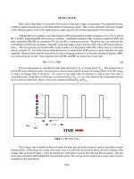
The sketch below shows the scope of the InAlk Complex. Licensor shall
recommend a process unit configuration to meet this duty specification.
INDIRECT ALKYLATION
DUTY SPECIFICATION
A
FOSTER WHEELER ENERGY LTD
PROCESS DOCUMENT
3550-8110-PD-028-0001
PAGE 3 OF 10
REV D1
3550-8110-PD-028-0001.doc DSN: 552
Figure 2-1 InAlk Unit Scope
3. BASIS OF DESIGN
3.1 Design Objective
The InAlk Complex shall be designed to process RFCC C
4
s to maximise production
of high octane Alkylate suitable for gasoline blending based on maximising octane-
barrels.
The Unit will also produce a mixed saturated C
4
s stream, which is sent to the LPG
pool.
3.2 Design Capacity
The InAlk Complex shall be designed to process the following quantities of the
design feedstock.
Table 3-1: Feedstocks to InAlk unit
Feedstock
Flow rate
Tonnes/hr
RFCC C
4
s 85 ( ~ 21,500 BPSD)
3.3 Design Feed Cases
There are two design cases for the InAlk Complex:-
Case 1: Based on maximum propylene production in the RFCC (0.90 wt%
Butadiene)
Case2: Based on maximum gasoline production in the RFCC
The InAlk Complex shall be designed to run at 100% capacity with feed from
storage whilst meeting all the product specifications.
The feedstock pressures and temperatures are provided in section 4. Properties
of the InAlk Complex feedstock are given in Table 3-2 below.
Feed
Pre-treatment
RFCC
InAlk
H
2
C
4
s
Butanes
Alkylate
Unsat.
Gas Plant
C
3
s
H
2
INDIRECT ALKYLATION
DUTY SPECIFICATION
A
FOSTER WHEELER ENERGY LTD
PROCESS DOCUMENT
3550-8110-PD-028-0001
PAGE 4 OF 10
REV D1
3550-8110-PD-028-0001.doc DSN: 552
3.4 Feedstock Properties
The specification of C
4
s stream to the InAlk Complex is detailed in Table 3-2
below. Make-up hydrogen to the SHP reactor (pre-treatment Unit) and the
saturation reactor (InAlk Unit) is specified in Table 3-3.
Table 3-2: Properties of Feedstock to the InAlk Complex
Parameter Units Max Gasoline Max Propylene
Specific Gravity -
0.596
0.600
Molecular Weight
Sulphur wt-ppm
20 Max.
20 Max.
H
2
S wt-ppm
1
1
Basic N
2
wt-ppm
1 Max. 1 Max.
Carbonyl Sulphur wt-ppm
1 Max. 1 Max.
Chloride, Fluoride wt-ppm
1 Max. 1 Max.
Total Oxygen wt-ppm
0.5 Max. 0.5 Max.
(NH
3
, Amines, caustic) wt-ppm
1 Max.
1 Max.
Metals wt-ppb
1 Max. 1 Max.
CO, CO
2
wt-ppb
1 Max. 1 Max.
H
2
O
No Free water
No Free Water
Alcohols wt-ppm
1 Max.
1 Max.
Acetonitrile
wt-ppm
50 Max.
50 Max.
Acetone
wt-ppm
75 Max.
75 Max.
C
3
wt%
0.08
0.07
C
3
= wt%
0.06
0.06
i C
4
wt%
22.30
14.98
n C
4
wt%
6.02
5.87
1 C
4
=
wt%
14.72
15.26
t-2 C
4
=
wt%
21.02
22.32
c-2 C
4
= wt%
14.29
15.30
Iso C
4
= wt%
20.64
24.74
Butadiene
wt%
0.37
0.9
C
5
+
wt%
0.50
0.50
Licensor to optimise the feed pre-treatment scheme to meet the requirement of the
InAlk reaction section.
Table 3-3: Make-up Hydrogen Specification for SHP/saturation reactor
Parameter Unit Value
Hydrogen purity, min vol% 99.9
CO+CO
2
content, max ppmv 10
Chlorides, max ppmv 1
Methane & Nitrogen Balance
INDIRECT ALKYLATION
DUTY SPECIFICATION
A
FOSTER WHEELER ENERGY LTD
PROCESS DOCUMENT
3550-8110-PD-028-0001
PAGE 5 OF 10
REV D1
3550-8110-PD-028-0001.doc DSN: 552
3.5 Product Specifications
For the design feedstock and flowrate, the InAlk Unit shall meet the product
specifications outlined below.
Alkylate
Table 3-4: Alkylate Product Specification (Note 1)
Property Unit Specification Test method
Appearance
Clear and Free of
Sediment
Visual
Butanes wt% 1.5 max UOP 539
RON 97.6 ASTM D2699
MON 92.7 ASTM D2700
Total Sulphur content
wt-
ppm
<1 UOP 727
Product Distillation vol% ASTM D86
1 °C 38
5 °C 89.5
10 °C 102
30 °C 109.5
50 °C 112
70 °C 116
90 °C 170
95 °C 206.5t
End point °C 205
SG (15.6°C/15.6°C) 0.697 ASTM D1298
RVP @
o
C kPa 24.14
ASTM D4953/D 5191
Copper Corrosion (3hrs @ 50
o
C
Report
Oxidation Stability Report
Existent gum Wt% Report
Note 1 – Licensor to confirm product specifications
INDIRECT ALKYLATION
DUTY SPECIFICATION
A
FOSTER WHEELER ENERGY LTD
PROCESS DOCUMENT
3550-8110-PD-028-0001
PAGE 6 OF 10
REV D1
3550-8110-PD-028-0001.doc DSN: 552
LPG (Butanes)
(Note 1, 2)
Licensor is requested to provide the Mixed Butane product specifications from the
InAlk Unit based on an optimised design to meet this duty specification.
Specification Unit Test Method
Specific Gravity gm/cc Report
ASTM D-1657/
ASTM D-2598
Composition
Water wt% Report
Nitrogen wt% Report
Oxygen wt% Report ASTM D-2233
Hydrogen wt% Report ASTM D-2504
Methane wt% Report ASTM D-2163
Ethane wt% Report ASTM D-2163
Ethylene wt% Report ASTM D-2163
Propane wt% Report ASTM D-2163
Propylene wt% Report ASTM D-2163
n-Butane wt% Report ASTM D-2163
Iso-Butane wt% Report ASTM D-2163
1-Butene wt% Report ASTM D-2163
t-2-Butene wt% Report ASTM D-2163
c-2-Butene wt% Report ASTM D-2163
Iso-Butene wt% Report ASTM D-2163
1,2-Butadiene (Note 3)
ppmw
Report ASTM D-2163
1,3-Butadiene (Note 3)
ppmw
Report ASTM D-2163
C
5
+ wt% 1 max ASTM D-2163
Sulphur Dioxide ppmw Report
Carbon Monoxide ppmw Report ASTM D-3416
Carbon Dioxide ppmw Report ASTM D-3416
Hydrogen Sulphide ppmw Report ASTM D-2420
Methyl Acetylene ppmw Report
Propadiene ppmw Report
Total Mercaptans S ppmw Report ASTM D-3227
COS ppmw Report
CS
2,
ppmw Report
Arsine ppbw Report ASTM E-819
Phosphine ppbw
NH
3
ppmw Report
Copper strip corrosion
(1h @ 38
o
C)
Report ASTM D-1838
Amine ppmw
Note 1 – Licensor to confirm product specifications
Note 2 – Max. Olefin content (incl. Butedienes) shall be < 1 vol% (over 24 hrs)
Note 3 – Max. Butedienes content shall be < 100 wppm
INDIRECT ALKYLATION
DUTY SPECIFICATION
A
FOSTER WHEELER ENERGY LTD
PROCESS DOCUMENT
3550-8110-PD-028-0001
PAGE 7 OF 10
REV D1
3550-8110-PD-028-0001.doc DSN: 552
3.6 By-product Specifications
The following by-products are expected to be produced in the InAlk Complex:
• Off-gas to LRU/RFCC Amine Stripper
• Sour water to sour water stripping (SWS1)
• Oily contaminated water to Effluent Treatment Plant (ETP)
Licensor is requested to provide the process conditions and composition of the
above streams in addition to any further by-product streams not stated above.
3.7 Specific Design Requirements
3.7.1 Feedstock specification
Licensor shall optimise the InAlk Complex design to process the feedstock as
determined in Sections 3.3 and 3.4.
Licensor is requested to provide a qualitative analysis regarding the flexibility of
the proposed configuration in terms of changes in operation / feedstocks,
particularly with respect to the RFCC mode of operation.
3.7.2 On stream factor
The InAlk Complex shall be designed for a minimum on-stream factor of 0.95.
This is equivalent to 8320 hours operation per calendar year.
On stream factor is defined as follows:
On stream Factor = (1) / ((1) + (2))
(1) = total duration of productive operation
(2) =total duration for repairs and maintenance including turnaround, catalyst
change-out and typical trip outage.
3.7.3 Turndown
The InAlk Complex shall be designed to operate satisfactorily in all operating
modes, as a minimum, in the range 40% to 100% of design feed rate for the feed
cases defined in section 3.3 and 3.4 while meeting all product specifications.
3.7.4 Cycle length
Licensor to specify cycle length. All equipment shall be specified and spared to
support maximum continuous operation between major turnarounds (4 years).
In series SPA reactor arrangement to be used to permit catalyst change out while
the unit is in operation to achieve the required period between major turnarounds.
INDIRECT ALKYLATION
DUTY SPECIFICATION
A
FOSTER WHEELER ENERGY LTD
PROCESS DOCUMENT
3550-8110-PD-028-0001
PAGE 8 OF 10
REV D1
3550-8110-PD-028-0001.doc DSN: 552
3.7.5 Specific Design Features
Alkylation reaction temperatures to be optimised to achieve optimum octane barrel
production. The Complex is to be capable of operating in maximum alkylate mode
if required. Facilities to monitor and control alkylate conversion shall be included.
Facilities to monitor and control water injection shall be included.
Licensor to design the Complex to minimise off spec alkylate production (e.g. at
start up) and include necessary facilities to enable reprocessing. The Complex
should be designed to produce saturated LPG. That is, to route all product from
the SPA reactors through to the saturation reactor.
3.7.6 Direct Feed and Feed from Storage
The InAlk Complex shall be designed to run at 100% capacity with feed directly
from RFCC or storage.
3.7.7 Process and Energy Efficiency
Licensor’s design shall optimise the consumption of energy and utilities. It is
expected that Licensor’s proposed process will incorporate a high level of heat
integration in order to provide optimum refinery efficiency.
Licensor shall investigate the potential for recovery of low grade heat from the
process unit and utilities systems.
Licensor shall base the inclusion of energy integration processes against a
payback time of 8 years.
Licensor shall comment on opportunities to improve process and energy efficiency
by use of Advanced Process Control.
Steam is expected to be used for reboiler duties.
3.7.8 Design Guidelines for Process and Equipment
Guidelines for the design of process and equipment are listed in document 3550-
8110-PD-0006. The guidelines are used to achieve a consistent design approach
across the project. These are not intended to supersede the Licensors design
requirements, or any criteria which may impact the Licensors guarantees.
3.7.9 Material Selection and Corrosion Inhibition
Licensor shall specify any particular metallurgical, corrosion inhibition monitoring
or injection requirements.
3.7.10 Major Compressor Driver Selection
Major compressor driver selection shall be specified by the Licensor with
justification for the selection between steam turbine and motor drives.
3.7.11 Catalyst Regeneration
Licensor shall specify the required method for regeneration and replacement of all
catalysts used in the InAlk Complex.
INDIRECT ALKYLATION
DUTY SPECIFICATION
A
FOSTER WHEELER ENERGY LTD
PROCESS DOCUMENT
3550-8110-PD-028-0001
PAGE 9 OF 10
REV D1
3550-8110-PD-028-0001.doc DSN: 552
The units that require in-situ catalyst regeneration shall be designed accordingly,
including any additional equipment if required.
3.7.12 Catalyst Handling
Licensor shall specify all permanent facilities required to load and unload catalysts,
including all equipment required for pre-sulphiding/hydrartion/reduction of catalysts
in situ, if required. Licensor shall provide guidance as to any special conditions
relating to these operations and any effluent problems that might be expected.
Licensor to recommend catalyst disposal method to avoid disposal of catalyst to
land fill.
3.7.13 Chemicals
Licensor shall specify facilities for the storage and preparation of chemicals
required for the normal operation of the complex, or required to facilitate the
Complex shutdown and maintenance.
3.7.14 Effluents and Emissions
Licensor shall identify all effluent streams (gaseous, liquid and solid) arising from
the process during normal operation and significant abnormal operations.
Estimated rates and compositions shall be provided for each stream, together with
recommendations for safe treatment and disposal. This should include all
transient & intermittent operations such as start-up and shutdown, catalyst
loading/unloading etc.
Specifically vent gas and wastewater streams should be treated to remove dioxins,
if present, within the licensed units.
3.7.15 Purging and flushing
Licensor shall specify any special facilities required for the purging and flushing of
equipment and instruments. Licensor shall identify purging and flushing mediums
and estimated rates of consumption.
3.7.16 Start-up and shutdown
Licensor shall specify any special facilities required to facilitate smooth and safe
start-up/shutdown of the InAlk Complex. This shall include shutdown of individual
units where the process allows.
3.7.17 Process Control, Safety and Shutdown Systems
The InAlk Complex design shall incorporate the use of modern state-of-the-art
process control systems and shutdown logic systems. Licensor shall specify all
necessary process control systems and safety shutdown logic systems required to
support the safe operation and maintenance of the InAlk Complex.
3.7.18 Flare Loads and Flare Design
Licensor shall specify all safety / pressure relief valves required to protect the units
and equipment within the InAlk Complex. Licensor shall also quantify the relief
loads arising from controlling, common mode and significant relief scenarios for
each safety/pressure relief valve (e.g. utility failure, blocked-in, external fire, etc).
INDIRECT ALKYLATION
DUTY SPECIFICATION
A
FOSTER WHEELER ENERGY LTD
PROCESS DOCUMENT
3550-8110-PD-028-0001
PAGE 10 OF 10
REV D1
3550-8110-PD-028-0001.doc DSN: 552
3.8 Utilities
Design data for available utility supplies are given in the Basic Engineering Design
Data (BEDD) document 3550-8820-SP-0001.
Licensor shall identify all utility consumption requirements and provide estimated
rates of consumption for normal operation and for significant abnormal operations.
Licensor shall specify all other raw materials required for the InAlk Complex in
addition to the feedstock, hydrogen, catalysts, chemicals and utilities discussed in
this document. This specification shall include materials, hazard data, method of
use, frequency of use and consumption. The design shall include all specialised
equipment required for their use.
4. BATTERY LIMIT CONDITIONS
Table 4-1 shows the envisaged key battery limit stream conditions for the InAlk
Complex. The table is not intended to be exhaustive and Licensor is requested to
provide a full list of battery limit streams and conditions.
These battery limit conditions shall apply when the InAlk Complex is operating at
design throughput.
Table 4-1: InAlk Complex Battery Limit Conditions
Process Streams From To Pressure kPag Temp °C
RFCC Olefin Feed Storage SHP Unit 800 42
RFCC Olefin Feed RFCC C3/C4 Splitter SHP Unit 650 42
Make-up Hydrogen
Hydrogen
Distribution
SHP Unit 4000 55
Product Alkylate Rerun Column Alkylate Storage 600 42
Product Butane Debutanizer LPG Storage
800
42
Heavy Oil/Off-spec.
Alkylate
Rerun Column
RFCC Gasoline Slop
Tank
600 42
Heavy Oil Rerun Column
RHDS Diesel
Storage
600 42
Wastewater SHP Unit
Sour Water Stripping
(SWS1)
600 42
Wastewater SHP Unit
Effluent Treatment
Plant (ETP)
600 42
Off-gas Unit
LRU/RFCC Amine
Stripper
1000 44
5. PROCESS GUARANTEES
A complete definitive list of process performance guarantees for the InAlk Complex
is specified in the guarantee agreements.