Proceedings VCM 2012 32 bộ điều khiển chống lắc cho cần cẩu container
Bạn đang xem bản rút gọn của tài liệu. Xem và tải ngay bản đầy đủ của tài liệu tại đây (414.32 KB, 6 trang )
Tuyển tập công trình Hội nghị Cơ điện tử toàn quốc lần thứ 6 231
Mã bài: 47
Bộ điều khiển chống lắc cho cần cẩu container
hoạt động trên mặt biển
A pendulation control system of an offshore container crane
Quang Hieu Ngo
1
,*, Trungtinh Tran
1
, and Keum-Shik Hong
2
1
College of Technology, Can Tho University, Vietnam (Email: {nqhieu, tttinh}@ctu.edu.vn)
2
School of Mechanical Engineering, Pusan National University, Korea (Email: )
Tóm tắt
Trong bài báo này, một hệ thống điều khiển chống lắc cho hệ cần cẩu trên biển được trình bày. Hệ cần
cẩu này được sử dụng để vận chuyển container qua lại từ tàu chở container có trọng tải lớn được neo đậu
trên biển và tàu được trang bị cần cẩu. Mục tiêu điều khiển là triệt tiêu hoàn toàn dao động lắc của
container trong quá trình bốc dỡ dưới tác động của sóng biển tác động lên các con tàu. Phương pháp điều
khiển được đề nghị là sự kết hợp giữa bộ điều khiển chống lắc thông thường và việc bù chuyển động của
tàu. Sự kết hợp này đảm bảo container được vận chuyển đến vị trí qui định. Kết quả thực nghiệm được
trình bày nhằm đánh giá tính khả thi của phương án điều khiển.
Abstract: In this paper, a method to control the pendulum motion of an offshore container crane is
discussed. The offshore container crane is used to load/unload containers between a huge container ship
(called the “mother ship”) and a smaller ship mounted cranes (called the “mobile harbor”). The control
objective during load/unload container is to control the pendulum motion (i.e., “sway”) of the load in the
presence of the mobile harbor motions (heave, roll, and pitch) induced by wave to keep the spreader at the
desire position. Experiment results are provided to demonstrate the ability of the proposed control method.
1. Introduction
Container cranes are widely used to transfer
containers and other objects from and to various
locations in ports and at container terminals. In
recent years, with the rapid growth of the world
logistics industry and the rises in competition
and costs, ship companies have resorted to
making container ships larger. The largest
container ship having the capacity 13,800 TEU
(twenty-foot equivalent unit) was launched by
Samsung Heavy Industries, a Korean company,
in 2008. Now, the designs of 16,000-TEU-class
ships have been completed and are waiting for an
order. It is predicted that by the 2020s, super
large, 18,000 TEU container ships will be in
operation. To keep up with ever-increasing ship
sizes, container cranes have to become larger,
faster, and higher, necessitating, in turn, efficient
controllers that can both guarantee fast turnover
times and meet stringent safety requirements.
Despite these improvements, one problem has
remained for small container terminals and ports:
they cannot accommodate, owing to their
relatively shallow water, the larger container
ships. To solve this problem, special crane-
equipped ships (“mobile harbor (MH)”) capable
of operating on the open sea have been
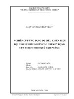
introduced. Fig. 1 shows a mobile harbor that
loads containers to and unloads them from a
mega container ship in open sea. A small ship
has a container crane and is connected to a
container vessel by a mooring system. The vessel
is assumed to be fixed on the ocean. It is not
affected by the sea wave because of its mass. The
mooring system between the crane ship and the
vessel imposes constraint oscillations on the
crane ship. Thus, only three motions of the crane
ship are considered: heaving, rolling and pitching
motions.
In the process of loading/unloading containers,
the longitudinal and lateral motions of the trolley
(especially when starting or stopping, along with
wave-induced ship movement) impart a
pendulum motion to the suspended container [1].
This type of motion can not only lead to a
potentially serious damage, but also prolong the
time required for precise positioning of the load.
Although an MH crane can perform anti-swing
control in the conventional approach [2-13], it
still needs to compensate non-negligible, relative
rotations. Because both the MH ship and the
232 Quang Hieu Ngo, Trungtinh Tran and Keum-Shik Hong
VCM2012
container ship are heaving, rolling, and pitching
in the waves, the trolley have to move to
compensate for the ship motions so that the
spreader can land on the top of the containers,
which its position is considered as a fix position
on the container ship.
The trolley of the offshore container crane is
redesign so that it can suppress both longitudinal
and lateral sway motions and compensate for the
ship motions. The structure of the trolley consists
of two stages. First stage is the main trolley and
is used to move the container from the vessel to
the crane ship or vice
Fig. 1. Loading/unloading of containers at a
mobile harbor in an open sea.
versa. Second stage has a relative motion with
the main trolley in two perpendicular directions.
The sway motions of the load are suppressed by
using these relative motions.
This paper represents the inaugural work of
mobile harbor studies. Here, for the first time,
the necessity of a new mechanism for the mobile
harbor is identified, and treated, from a control
point of view. The motion of the trolley is used
not only eliminating the sway motion but also
compensating for the ship motions to keep the
spreader at
the desire position. Therefore, the control law
includes the sway suppression and the ship
motions compensation.
The paper is organized as follows. In Section 2,
the system dynamics of an offshore container
crane are provided. In Section 3, an anti-sway
control law is proposed, and corresponding
trajectories is introduced. In Section 4,
experiment results are discussed. Finally,
conclusions are drawn in Section 5.
2. Problem formulation
To develop a mathematical model of the whole
system, three coordinate systems are introduced
in Fig. 2. The first one is the global coordinate,
O
0
x
0
y
0
z
0
. The second one is the crane ship
coordinate, O
s
x
s
y
s
z
s
, with the origin at the center
of gravity of the ship. The last coordinate is the
trolley coordinate, O
t
x
t
y
t
z
t
, which is fixed on the
main trolley. Using these coordinates, the
mathematical model can be derived as follow
[14].
,)()(),()( uqGqqDqqqCqqM
(1)
where
,sinsin
,coscos
,
,0,0,,
,
0
0
0
,
,
00
00
00
00
,,,,
,
0
0
0
0
,,,,
4114
3113
11
434241
34333231
242321
141312
4241
3231
2221
1211
4321
444241
333231
242322
141311
lmmm
lmmm
mmm
ff
ccc
cccc
ccc
ccc
dd
dd
dd
dd
gggg
mmm
mmm
mmm
mmm
yx
p
p
pt
T
yx
T
T
u
qqC
D
qG
qM
q
Fig. 2. Introduced coordinate frames: reference
(mother ship), ship, and trolley.
Mother ship
Mo
bile harbor
(Small ship)
Tuyển tập công trình Hội nghị Cơ điện tử toàn quốc lần thứ 6 233
Mã bài: 47
.cossin
,cossin2
cossincos2
sinsinsin2
,cossin
,cossin
,cossin
,sincoscos2
cossincos2
,sincos
,sinsinsinsincos
coscossin
,sinsinsin
coscossin
,sin
,cossinsincos
,cossinsincos
,sin2
,
,cos
,
,coscos
cossinsin
,sincossin
2
43
42
41
2
34
2
33
32
31
24
23
21
14
13
12
2
44
22
33
22
4224
3223
lmc
lm
lm
lmc
lmc
lmc
lmc
lm
lmc
lmc
lmlm
lmc
lm
lmc
mmc
lmlmc
lmlmc
mmc
lmm
lmm
mmm
lm
lmmm
lmmm
p
p
p
p
p
p
p
p
p
p
pp
p
p
p
pt
pp
pp
pb
p
p
pt
p
p
p
m
t
and m
p
are the masses of the trolley and the
load, respectively. x and y represent the position
of the connection point between the main rope
and the trolley in the trolley coordinate frame. l
denotes the rope length, h is the crane height,
and
define the longitudinal and lateral sway
angles of the load in the reference coordinate
frame. z is the heave motion (displacement) of
the ship in the reference coordinate frame.
and
are the rolling and pitching angular
displacements of the ship, respectively, in the
reference coordinate frame.
3. Pendulation control system
The conventional control systems for container
crane are given as follow:
,
,
kekekf
kekekf
ypyydyy
xpxxdxx
(2)
where k
dx
, k
px
, k
, k
dy
, k
py
, and k
are the control
gains,
dx
xxe and
dy
yye
are position
errors in x and y directions. x
d
and y
d
are desire
positions of the trolley.
During loading/unloading process, the ship
motions impart to the sway motion of the
payload even thought the main trolley has been
moved to the desire position. The control
objective in this situation is to keep the payload
in the small acceptable region, which is
predetermined by a global desire position (X
d
and
Y
d
). Without loss of generality, X
d
and Y
d
are
assumed to be constants. In practical, the trolley
must move following trajectories to keep the
payload in the desire region. The trajectories can
be obtained due to the ship motions as follow.
.
cos
sin
,
cos
cossinsinsin
hY
y
hyX
x
d
d
d
d
(3)
The objective of the control law must be
minimize the position error while tracking the
trajectory (3), and suppressing the sway motion,
and
. The control diagram is given in Fig. 3.
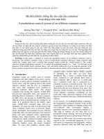
4. Experimental results
4.1 Experiment model
Experiment model using in the paper includes
a 6-degree-of-freedoms (6DOFs) platform to
generate the ship motions induced by random
waves and a 3-dimensional (3D) crane. The 3D
crane is placed on the top of the 6DOFs platform
as shown in Fig. 4.
The Marine System Simulator (MSS) [15] is
used to simulate the ship motions induced by
random waves. The 6DOFs platform is control to
follow the simulation data from MSS. An inertial
measurement unit (IMU), a MTi sensor from
XSENS, measures real-time motions of the
platform. Fig. 5 presents the roll motion of the
platform with simulation result and the
measurement result from IMU.
,
,
z
,,, yx
Fig. 3. Control diagram.
234 Quang Hieu Ngo, Trungtinh Tran and Keum-Shik Hong
VCM2012
Fig. 4. Experiment model including 6DOFs
platform and 3D Crane.
4.2 Results
The control gains in (2) are tuned by controlling
the trolley to desire position without the ship
motions. Fig. 6 shows the trolley position and the
sway angle in Y direction. The trolley reaches the
desire position and suppresses the sway angle
well. Fig. 9 presents the position of the payload
with free motion (without control), sway control
without tracking the trajectories (3), and sway
control with tracking trajectories (3). Without
tracking, the payload moves in the large region
even thought the sway control is applied. With
tracking, the position of the payload is in the
small region (-0.04m, 0.04m). This result seems
good in the experiment conditions by using the
conventional control law. However, the new
control law must be designed to improve
performance before it can be implemented in the
practice.
0 20 40 60 80 100 120 140 160 180 200
-0.08
-0.06
-0.04
-0.02
0
0.02
0.04
0.06
0.08
Time [sec]
Pitchl motion of the ship [rad]
Simulation result from MSS
Platform's motion
(a) Pitch motion of the ship
0 20 40 60 80 100 120 140 160 180 200
-0.08
-0.06
-0.04
-0.02
0
0.02
0.04
0.06
0.08
Time [sec]
Roll motion of the ship [rad]
Simulation result from MSS
Platform's motion
(b) Roll motion of the ship
0 20 40 60 80 100 120 140 160 180 200
-0.08
-0.06
-0.04
-0.02
0
0.02
0.04
0.06
0.08
Time [sec]
Error [rad]
Roll motion
Pitch motion
(c) Error between simulation and replicated
motion in the platform
Fig. 5. Comparison of the ship motions in Sea
State 3 (simulation vs. replicated motion in the
platform).
0 1 2 3 4 5 6 7 8 9 10
0.1
0.15
0.2
0.25
0.3
0.35
0.4
0.45
0.5
Time [sec]
Trolley position [m]
(a) Trolley position.
Tuyển tập công trình Hội nghị Cơ điện tử toàn quốc lần thứ 6 235
Mã bài: 47
0 1 2 3 4 5 6 7 8 9 10
-0.1
-0.05
0
0.05
0.1
Time [sec]
Sway angle [rad]
(b) Sway angle.
Fig. 6. Control perfomance of the crane with
out ship motions.
-0.1 -0.05 0 0.05 0.1
-0.08
-0.06
-0.04
-0.02
0
0.02
0.04
0.06
0.08
Payload position in X [m]
Payload position in Y [m]
(a)
-0.1 -0.05 0 0.05 0.1
-0.08
-0.06
-0.04
-0.02
0
0.02
0.04
0.06
0.08
Payload position in X [m]
Payload position in Y [m]
(b)
-0.1 -0.05 0 0.05 0.1
-0.08
-0.06
-0.04
-0.02
0
0.02
0.04
0.06
0.08
Payload position in X [m]
Payload position in Y [m]
(c)
Fig. 7. Position of the payload in XY plane in
case of free motion (a), sway control with out
tracking (b), and sway control with tracking (c).
5. Conclusions
The conventional control has been applied for
the offshore container crane. The control law
suppresses the sway motion and tracks the
trajectory to keep the payload in the acceptable
region. The experiment has been performed to
demonstrate the proposed idea for position
tracking and sway suppression. However, for
perfect suppression of the sway motion of the
payload, the control algorithm should be
improved.
References
[1] Q. H. Ngo and K S. Hong, “Sliding mode
control of an offshore container crane,”
IEEE/ASME Trans. Mechatron., vol. 6, no. 5,
pp. 662-668, 2012.
[2] K. L. Sorensen, W. Singhose, and S.
Dickerson, “A controller enabling precise
positioning and sway reduction in bridge and
gantry cranes,” Control Eng. Practice, vol.
15, no. 7, pp. 825-837, 2007.
[3] K. T. Hong, C. D. Huh, and K S. Hong,
“Command shaping control for limiting the
transient sway angle of crane systems,” Int. J.
Control Autom. Syst., vol. 1, no. 1, pp. 43-53,
2003.
[4] K S. Hong, B. J. Park, and M. H. Lee, “Two-
stage control for container cranes,” JSME Int.
J. Ser. C, vol. 43, no. 2, pp. 273-282, 2000.
[5] H. Kawai, Y. B. Kim, and Y. W. Choi, “Anti-
sway system with image sensor for container
cranes,” J. Mech. Sci. Technol., vol. 23, no.
10, pp. 2757-2765, 2009.
[6] D. Chwa, “Nonlinear tracking control of 3-D
overhead cranes against the initial swing
angle and the variation of payload weight,”
IEEE Trans. Control Syst. Technol., vol. 17,
no. 4, pp. 876-883, 2009.
[7] H. Park, D. Chwa, and K S. Hong, “A
feedback linearization control of container
cranes: Varying rope length,” Int. J. Control
Autom. Syst., vol. 5, no. 4, pp. 379-387, 2007.
[8] Y. S. Kim, K S. Hong, and S. K. Sul, “Anti-
sway control of container cranes:
Inclinometer, observer, and state feedback,”
Int. J. Control Autom. Syst., vol. 2, no. 4, pp.
435-449, 2004.
[9] Q. H. Ngo, K S. Hong, and I. H. Jung,
“Adaptive control of an axially moving
system,” J. Mech. Sci. Technol., vol. 23, no.
11, pp. 3071-3078, 2009.
[10] C. S. Kim and K S. Hong, “Boundary control
of container cranes from the perspective of
controlling an axially moving string system,”
Int. J. Control Autom. Syst., vol. 7, no. 3, pp.
437-445, 2009.
236 Quang Hieu Ngo, Trungtinh Tran and Keum-Shik Hong
VCM2012
[11] H. H. Lee, Y. Ling, and D. Segura, “A sliding
mode antiswing trajectory control for
overhead cranes with high-speed load
hoisting,” J. Dyn. Syst. Meas. Control-Trans.
ASME, vol. 128, no. 4, pp. 842-845, 2006.
[12] M. S. Park, D. Chwa, and S. K. Hong, “Anti-
sway tracking control of overhead cranes with
system uncertainty and actuator nonlinearity
using an adaptive fuzzy sliding-mode
control,” IEEE Trans. Industrial Electronics,
vol. 55, no. 11, pp. 3972-3984, 2008.
[13] Q. H. Ngo and K S. Hong, “Skew control of
a quay container crane,” J. Mech. Sci.
Technol., vol. 23, no. 12, pp. 3332-3339,
2009.
[14] K S. Hong and Q. H. Ngo, “Dynamics of the
container crane on a mobile harbor,” Ocean
Engineering, vol. 53, pp. 16-24, 2012.
[15] T. I. Fossen and Ø.N. Smogeli, “Nonlinear
time-domain strip theory formulation for low-
speed manoeuvring and station-keeping,”
Model. Identif. Control, vol. 25, no. 4, pp.
201-221, 2004.
Quang Hieu Ngo received the
B.S. degree in mechanical
engineering from Ho Chi Minh
City University of Technology,
Vietnam, in 2002, the M.S.
degree in mechatronics from
Asian Institute of Technology,
Thailand, in 2007, and the
Ph.D. degree in intelligent control and
automation from Pusan National University,
Korea. He has worked as a lecturer on the
College of Technology – Can Tho University
from 2002. His current research interests include
port automation, control of axially moving
systems, sliding mode control, adaptive control,
and input shaping control.
Trungtinh Tran received the
B.Sc. degree and post graduate
diploma from Cantho
University, Vietnam and
University of Professional
Education Larenstein, The
Netherland, in 1997 and 2001
respectively, the M.S. and Ph.D. degrees from
Gyeongsang National University, Korea in 2004
and 2007 respectively. His research interest
includes power system expansion planning,
transmission expansion planning, power system
operation, power system reliability evaluation,
power system market, applied fuzzy set theory.
Especially, he has been researching electricity
market, renewable energy and energy saving. He
has worked as a lecturer on the College of
Technology – Can Tho University.
Keum-Shik Hong received
the B.S. degree in mechanical
design and production
engineering from Seoul
National University in 1979,
the M.S. degree in mechanical
engineering from Columbia
University, New York, in 1987, and both the
M.S. degree in applied mathematics and the
Ph.D. degree in mechanical engineering from the
University of Illinois at Urbana-Champaign
(UIUC) in 1991. From 1991 to 1992, he was a
Postdoctoral Fellow at UIUC. Since Dr. Hong
joined the School of Mechanical Engineering at
Pusan National University (PNU), Korea, in
1993, he became Professor in 2004. Dr. Hong’s
current research interests include nonlinear
systems theory, adaptive control, distributed
parameter systems control, vehicle control, brain
computer interface, and innovative control
applications in brain engineering.