MAKE Architectural Design Report Rev 02: January 2007 abridged
Bạn đang xem bản rút gọn của tài liệu. Xem và tải ngay bản đầy đủ của tài liệu tại đây (5.77 MB, 40 trang )
Architectural
Design Report
Rev 02: January 2007
2 make The Cube Architectural Design Report Rev. 02 January 2007
Cover image: GMJ
124-126 Wharfside Street
The Mailbox
Birmingham B1 1RQ
tel +44 (0) 121 632 1111
fax +44 (0) 121 632 1455
www.makearchitects.com
4 make The Cube Architectural Design Report Rev. 02 January 2007
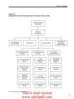
Key project data Glossary diagram
Washington Wharf
canal
foot
bridge
The Mailbox
Salvage Wharf
bars and
restaurants
building
piazza level
Building B
Base ‘278’ works
Enhanced ‘278’ works
Washington Court
Holliday Wharf
towpath level
The Postbox
The Cube
Wharfside Street
Commercial Street
Design team
Client: Birmingham Development
Company Ltd (BDC)
Architect: Make
Cost consultant: Faithful + Gould
Employer’s agent: Faithful + Gould
Civil/structural engineer: Buro Happold
Services engineer: Hoare Lea
Acoustics: Hoare Lea
Fire consultant: Faber Maunsell Fire
Note: illustrations in this report are indicative only and the
latest design drawings should be referred to for the current
layouts and details.
Design fundamentals
Site area: 4,100 m
2
Cube dimension: 53.1m
Overall building height: approximately 66m above
Commercial Street level
Structure: part concrete frame and part steel frame
Cladding: anodised aluminium panels with opaque and
translucent glazed panels. Plant building brick clad.
King and
Queens
Court
Brough
Passage
Link to The Mailbox
Contents
Key project data
Glossary diagram
01 Introduction
Project ambition
Design concept
02 Site and context
Site location
Character of surrounding area
Building on the success of The Mailbox
Surrounding buildings
03 Building form
Strategic design moves
Mix of uses
Entrances and routes
Automated parking system
Retail, cafe-bar levels
Office levels
Residential levels
Hotel levels
Sky bar and restaurant
Roof
Building B
04 Building envelope
Description of external wall systems
05 Internal planning
Definition of shell and core areas
Office fit out
Apartment fit out
Entrances and lobbies
06 Logistics
Loading bay and service strategy
Waste management and recycling
Cleaning, maintenance and glass
replacement
Designing out bird nuisance
Sustainability
Wind condition studies
Access for all
07 Works beyond the site boundary
‘278’ works
Refurbishment of footbridge
Covered link to The Mailbox
08 Illustrations
01 Introduction
Photo by Zander Olsen
10 make The Cube Architectural Design Report Rev. 02 January 2007
Project ambition
The Mailbox has established itself as a vibrant mixed-use
development integral to Birmingham’s city centre life.
The Cube is the final phase of this scheme, and will reinforce
The Mailbox’s position as a key urban destination.
The Cube is firmly knitted into its context, and actively draws
people through the site to become a new hub for pedestrians.
The new building establishes a strong visual presence and is
immediately identifiable as a gateway to the canal and city
centre.
The lower levels are dedicated to retail with cafe-bars and
restaurants animating the canalside. Offices, residential
apartments and a hotel occupy the levels above and a skyline
restaurant is located at the top offering panoramic views over
the canal and city.
The Cube’s façade is as visually exciting as its form. A modular
system creates an anodised aluminium clad exterior fretwork
screen while the interior spaces are lined with glass. Together,
the intricate exterior tessellations and the courtyard’s glowing
reflections evoke Birmingham’s strong manufacturing and
engineering tradition, as well as its jewellery and watchmaking
heritage.
With its cutting edge design, rich mix of uses and creation
of a convergence point, the new building is pivotal to
Birmingham’s continued revitalisation. The Cube’s powerful
geometric form and shimmering texture will complement The
Mailbox building and introduce a distinctive new presence to
the city skyline.
12 make The Cube Architectural Design Report Rev. 02 January 2007
Design concept
An iconic form
A unique landmark on Birmingham’s skyline
a ‘full stop’
to The
Mailbox
and a new
front door
to the city
centre
At ground level, the ‘cube’ hovers over a glass
plinth. One glazed retail storey at Commercial
Street opens through to two floors of cafe-
bars looking out over the canalside, exploiting
the natural fall of the site.
A diagonal pedestrian route cuts through the
retail levels, linking the street to the towpath,
the footbridge, and The Mailbox piazza.
The four-storeys of shops, bars and cafes, and
the entrances to the offices, apartments and
hotel are all accessed from the central open
courtyard. Twisting up over seventeen floors,
the prismatic geometry and reflections of the
courtyard will create a dynamic shared space,
linking all the uses in the building.
At the residential floors, the courtyard opens
up on the canal-side, forming large terraces.
An open fretwork screen completes the
geometry of the ‘cube’ while allowing light, air
and view to the apartments.
In contrast to the jewel-like interior, the solid
metallic exterior of the cube creates a strong
landmark form in the cityscape.
The two-storey glazed rooftop structure -
housing hotel rooms, restaurant and bar - is a
continuation of the twisting courtyard facades,
acting as a dramatic beacon on the night
skyline.
02 Site and context
16 make The Cube Architectural Design Report Rev. 02 January 2007
Site location
The site lies to the south-west of the city centre, between
Commercial Street and the canal, between The Mailbox and
Washington Wharf.
The site is 10 minutes walk from New Street station, through
The Mailbox. It lies adjacent to the canal with a footbridge link
to the towpath on the other side, leading north to the Gas
Street basin, Brindleyplace and the ICC. The new registry office
development lies across the footbridge behind the Holliday
Wharf development.
Commercial Street is a relatively calm street. A large six-storey
residential development has recently been completed on the
south side of the street. Neighbouring Washington Wharf is a
relatively new residential courtyard scheme.
The St Thomas’ Church Peace Gardens lie a minute’s walk to the
south, towards Bath Row and the Attwood Green area beyond.
Commercial Street slopes down towards the city centre and
Brough Passage, to the east of the site, slopes down further to
the canalside. The maximum change in level across the site is
approximately 4.5m.
slopes up
+0m
-4.5m
-1.5m
slopes up
-4.5m
-3.5m
indicative site levels
Brough Passage
The Mailbox
Peace Gardens
Attwood Green
Bath Row
Holloway Head
illustration from BCC ‘Bath Row and Holloway Head Development Framework’, August 2004
site
footbridge
piazza level
towpath level
18 make The Cube Architectural Design Report Rev. 02 January 2007
Building on the success of The Mailbox
a strong destination
with a clear identity
within one mixed
use building
part of a successful
rejuvenated canal
environment
Character of surrounding area
canal as a leisure
destination
changing
character of
Commercial Street,
Bath Row and
Attwood Green
higher density
development in the
expanding city
centre
a site with a national profile
from the BBC studios
20 make The Cube Architectural Design Report Rev. 02 January 2007
Surrounding buildings
blank wall
windows
obscure
windows and
final exit
bridge
deck
Six-storey development, incl. refurbishment of
historic wharf building. Apartments above,
with bars and restaurants at towpath level.
New registry office behind.
Holliday Wharf
Washington Wharf
Four-storey residential development
completed in 1999/2000. Canalside block has
side windows looking out over the edge of the
site. Other walls on site boundary are blank.
Washington
Court
Two- and three-
storey residential
building.
The Postbox
Kings and Queens Court
The Mailbox
Six storey residential
development, with some
commercial units at street
level.
The new-build portion of The
Mailbox development,
completed in 2000. The five
storey building houses three
floors of commercial units
(mainly A3) and two storeys of
hotel.
The wall facing the site
includes some windows to the
stair core and, at the lower
levels, mainly obscure
windows to A3 units.
A final exit route from this
building over the site needs to
be maintained at all times.
Three storey residential
buildings built in the 1980s.
This portion of the canal side
is private, with a communal
garden for the residents.
looking back
towards
The Mailbox
small staircase
windows, final exit
and dry riser inlet
facing onto the
site
03 Building form
24 make The Cube Architectural Design Report Rev. 02 January 2007
Strategic design moves
The Cube is firmly knitted into
its site and actively draws
people through the site, to
become a new hub for
pedestrians. The diagonal
pedestrian route through the
central courtyard encourages
movement between the street
and footbridge level and the
towpath, a storey below.
A full stop
to The
Mailbox
and a new
front door
to the city
centre
The Mailbox
1. Connectivity 2. Terracing form
3. Rooftop structure
While the retail and office floor plates
completely surround the central courtyard, the
residential floors terrace back on the canal-
side to open up the courtyard and bring light
and views deep into the plan.
A fretwork screen ‘completes’ the cube form.
The glazed rooftop structure contrasts
strongly with the ‘cube’ element below and
makes a visual link with the faceted retail
glazing at the base.
This two-storey steel rooftop structure
houses a sky bar and restaurant at the
upper level, providing panoramic views of the
city and acting as a beacon on the skyline.
View of the
screen
from the
courtyard
The terracing form on the canal-side
26 make The Cube Architectural Design Report Rev. 02 January 2007
Mix of uses
25: sky bar and restaurant
24: hotel
23: hotel and residential
15 to 22: residential
9 to 14: office
(note: no level 13)
Building B (plant building)
5 to 8: retail and cafe-bars
2 to 4: car parking
Fretwork screen
The Mailbox Salvage Wharf
bars and
restaurants
building
The Cube
28 make The Cube Architectural Design Report Rev. 02 January 2007
Entrances and routes
Level 6
towpath
Level 7
street
towpath
entrance
Salvage Wharf
bars and restaurants
west resi
entrance
office entrance
access to
parking
gated route to towpath for
Washington Wharf
residents
parking garages
parking garages
cycle stores
cafe-bars
retail
courtyard void
shoppers’
lift
(serves
levels
5 to 8)
Brough Passage ramped
pedestrian route to street
Covered link to The Mailbox
by Associated Architects
car ramp
to street
Footbridge forms
towpath link to
Brindleyplace
‘piazza’ level of The Mailbox
towpath at level below
stair up to terrace at level above
Loading
bay
car ramp
to
parking
garages
bridge link
over
lobby for
hotel, sky bar
and east
residential
terraces for cafe-bars (level above towpath)
taxi drop-off
shared surface for
pedestrian priority
Brough Passage sloping down
to towpath
Commercial Street
Towpath level (level 6) is 4.5m below the level of Commercial
Street, the footbridge and the ‘piazza level’ of The Mailbox
(level 7). Pedestrians entering from Commercial Street can walk
through the heart of the open courtyard, taking the escalators
or lift down to the lower levels.
The shared lobby for the hotel, sky bar, restaurant and east
residential apartments has an entrance at the taxi-drop on
Commercial Street as well as an entrance onto the central
courtyard.
The office and west residential entrances are located at
towpath level.
Access to parking garages and the loading bay are located at
the west of the site. The loading bay is at street level while a
car ramp gives access to the parking garages located beneath
the loading bay.
service
vehicles
cars
in
cars
out
pedestrian and
fire access only
fire fighting
access to ramp
30 make The Cube Architectural Design Report Rev. 02 January 2007
Automated parking system
levels 4
3
2
Lifts with garage above
Car turned on turntable in lift
Double bank of cars - always
one empty space to move
front car into
Shuttle running in aisle
Lifts with garage above
Shuttle running in aisle
Typical system layout
Example of pallet-less system
Parking will be offered to residents and office workers, while visitors will use the
existing Mailbox car park. Due to the constrained site and level change across
the site, traditional basement parking would be very inefficient.
An automated parking system removes the need for anyone to enter the car park
and cars can be stacked more densely. A driver simply drops off their car in one
of the garages at level 6. A lift carries the car from the garage down to an aisle,
where a shuttles transports the car to an empty space.
To retrieve a car, the driver will call the car with a swipe card or fob and the car
will then be delivered to a specified garage.
For more detail, see specialist
contractor information.
street
ramp
liftlift
level 4
level 3
level 2
level 6
level 7
Fire fighting cores to all levels
aisle 1
aisle 2
ramp
32 make The Cube Architectural Design Report Rev. 02 January 2007
Retail, cafe-bar levels
levels 8
7
6
5
Level 6 plan of The Cube, Salvage Wharf and The Mailbox
(blue A3, purple A1)
Level 5
retail, cafe-bars
Public WCs
Artwork
Level 6 (towpath)
Retail, cafe-bars
Office entrance
West residential lobby
Level 7 (street and bridge level)
Retail, cafe-bars
Hotel and sky bar entrance
East residential lobby
Level 8 (first level of the cube)
Retail, cafe-bars
Views of the A1/A3 around the central courtyard:
Servicing strategy
The four levels of A1/A3 use extend from one level below towpath (5) to one level
above street level (8). The central courtyard extends throughout, so rain can fall
right down to its base at level 5. Local canopies and the natural overlapping of
the walkways provide shelter for pedestrians.
The different levels are connected by twisting escalators - spiralling around the
courtyard - as well as by a passenger lift (serving only levels 5 -8). The retail
levels are animated by particular uses and entrances, as shown below. A spa at
level 5 can also be accessible from the hotel discretely by the main hotel lifts.
Maximum population
From the loading bay at street level, goods will be transported
across the covered bridge-link from Building B into The Cube.
Goods will then be transported by goods lift G7 or G9.
Either units are served directly by these lifts, or goods are
taken down to level 5 where they can be moved to the other two
goods lifts, to serve the remaining units. Goods lifts G6 and G7
serve all levels of The Cube. Goods lifts G8 and G9 serve only
retail floors 5, 6, 7 and 8. All service corridors are a minimum of
2m wide and maximum 3m wide.
A3 units are primarily located on the canal-side, with outdoor
seating on the towpath, on canal-facing terraces and around the
internal courtyard. Units intake fresh air locally from the
central courtyard or from outside. Extract is ducted from each
unit and exhausted communally on the north east and south-
west elevations at level 8.
Canopies at level 9 over escalators
provide shelter
Artwork at level 5
Each retail unit will have a maximum occupancy depending on
use, size and location. Escape into the open courtyard is an
acceptable escape route but use of the escalators is not. Levels
6 and 7 will therefore accommodate greater populations that 5
and 8.
Public WCs
The following are provided at level 5:
Female: 4no. cubicles, incl. 1 accessible for ambulant disabled
Male: 2no. cubicles, 3no urinals
1no. unisex disabled WC
1no. Family room/baby change
Flexibility
It is desirable that level 8 could be used for office
or A1/A3 accommodation. The 4m floor-to-floor height allows
for this, with a 150mm raised floor zone and lift and escalator
access for both uses. Levels 5 to 8 will be constructed as shell
space.
Height
4.5m floor to floor levels 5, 6, 7 and 4m floor to floor level 8.
artwork
at base of
courtyard
Floor loading
Floor loading for retail units is 5kN/sq.m
34 make The Cube Architectural Design Report Rev. 02 January 2007
Office levels
levels 14
12
11
10
9
Tenant 1
Tenant 2
The five levels of office accommodation (9, 10, 11, 12, 14)
surround the central courtyard. The ‘twist’ of the courtyard is
created by the edges of the floor plates around the courtyard,
which alternate every two floors.
The fretwork screen extends down to level 12 so the glazing line
on the north west corner is adjusted on levels 12 and 14 to
accommodate the depth of the screen.
The office levels will be fitted out to Cat A standard and this is
described in more detail in section 05 ‘Internal planning’.
The floor plates can be subdivided into multiple tenancies. The
diagram on the facing page shows a two-tenant split.
Subdivision into smaller areas would require a longer length of
shared corridor. Four on-floor plant rooms each serve a
quadrant of the office floor plate, allowing great flexibility of
occupation.
Each floor plate is served by two fire-fighting cores. The stair
width and storey exit width is 1350mm. Faber Maunsell’s Fire
Safety Strategy sets the maximum population per office floor
as 270 people. The largest net floor area is 2079m
2
which gives
a maximum density of 1 person per 7.7m
2
.
Maximum population
Height
WC provision
The floor-to-floor height of 3.75m provides a floor-to-ceiling
height of 2.7m, with an overall raised floor build-up of 150mm
and overall ceiling build-up of 620mm.
Each floorplate provides:
2no. disabled WCs (to be within acceptable travel distances)
8no. unisex cubicles (half in each core)
BS 6465 Part 1 = 10no. WCs is sufficient for 225 people
Over 2079 sq.m, 225 people = 1 per 9.24m
2
In order to achieve an occupancy density higher than 1 per
9.24m
2
(max. 1 per 7.7m
2
) additional WCs could be installed as
part of a tenant’s Cat B fit out. Showers could also form part of
the tenant Cat B fit-out. The drainage design allows for this
possible future increase.
The offices are served by four lifts, accessed from the lobby
at towpath level 6. The parking garages are accessible from
the towpath lobby.
Each floor plate is served by two goods lifts, which also
serve the rest of The Cube. G7 is directly accessible from
the loading bay while G6 is accessible from the level 5
service corridor or, on infrequent occasions, from Brough
Passage.
Lifts and servicing
Plant
Plant
Plant
Plant
Lift lobby
Loading
Floor loading is 4kN/sq.m incl. partitions
36 make The Cube Architectural Design Report Rev. 02 January 2007
Residential levels
levels 23
to
15
Doors open in event
of fire only
arrows show escape routes
The residential floors are divided into east and west halves,
each served by two lifts. The west side is designated as
‘investor’ (predominantly rental property) and this is accessed
via a lobby at level 6. The east side, ‘owner-occupier’, is
accessed from the shared hotel/sky bar lobby at level 7.
The building form terraces back on each floor. There are large
areas of external terrace at level 15 and then small terraces on
the north-west side as the form terraces back. The twisting
courtyard form creates small balconies and ledges. There are
no in-board balconies.
The top level, 23, is residential on the west side (investor) but
hotel rooms on the eastern side.
Each floor plate is served by the two fire-fighting cores (storey
exit width 1350mm) and one dedicated escape stair (storey exit
width min. 850mm). The western dead-end is code-compliant,
at approx. 7.5m from the stair door to the furthest front door.
The dead end on the eastern side is double the code-compliant
travel distance, divided into two lengths of 7.5m with the
furthest section vented into an AOV shaft.
Many of the apartments have an internal travel distance of less
than 9m, not requiring a protected internal corridor. Where 9m
is exceeded, internal corridors protected by hold-open fire
doors are provided.
Fire safety
Height
The floor-to-floor height of 3m provides a floor-to-ceiling
height of 2.5m, with an overall floor build up of 120mm and
overall ceiling zone of 130mm.
Lifts and servicing
Two passenger lifts serve each half of each floor. One goods lift
serves each half.
Each half-floor contains one refuse store, which provides space
for general waste and recycling. Waste management is
discussed further in section 06 ‘Logistics’.
Apartments are heated by wet underfloor heating. Corridors,
lift lobbies and stair cores are not heated.
A ‘transfer zone’, nominally 750mm, between the lowest
residential floor (15) and the upper office floor (14) will be used
to transfer the soil stacks back to the main cores.
East
West
The terracing form behind
the fretwork screen
38 make The Cube Architectural Design Report Rev. 02 January 2007
Hotel levels
levels 24
23 (part)
Indicative layout: construction of shell and core only
Shell and core space
East side:
hotel
shell and
core
West side:
residential
fitted out
level 23:
half resi
half hotel
level 24
hotel
The hotel lifts are accessed through a lobby at street level 7
while the main hotel reception will be at level 24: the lower level
of the glazed rooftop structure. Hotel bedrooms will be
distributed across floors 24 and 23 (top floor of the cube: east
side hotel, west side residential).
The hotel space will be shell and core only and the bedroom
layout shown opposite is illustrative only. The soil stacks, which
will be coordinated with the apartments below, will restrict
possible hotel bathroom positions.
Due to the terracing of the building form, there are some areas
of external terrace. There will be no in-board balconies.
Fire safety
Height
Lifts and servicing
Two passenger lifts serve all the hotel floors and the sky bar
and restaurant from the lobby at level 7. These lifts will also
access the spa at level 5.
The hotel is served by the two shared goods lifts.
Due to the phased evacuation regime, Faber Maunsell’s Fire Strategy
sets a total population for the top three floors together: 23 (hotel and
resi), 24 (hotel) and 25 (sky bar), of 1,305 people with a maximum of
520 on any one floor. There will need to be agreement as to how this
maximum population is managed over the different uses.
Level 23: 3.5m floor to floor, 2.5m clear (120mm floor zone, 650mm ceiling zone)
Level 24: 3.6m floor to floor, 2.6m clear (120mm floor zone, nom. 500mm ceiling)
Loading
Floor loading is 5kN/sq.m incl. partitions, bathrooms and plant
40 make The Cube Architectural Design Report Rev. 02 January 2007
Sky bar and restaurant
level 25
Indicative layout: construction of shell and core only
Shell and core space
The sky bar and restaurant occupy the top level, giving
panoramic views over the city skyline. This level will be
constructed as shell and core only. The tenant fit out will
include the kitchen, welfare and WCs as well as the bar and
restaurant spaces.
The geometry of the rooftop structure naturally creates a
facetted soffit, cantilevering up at the perimeter where
possible to create panoramic views. The steel structure of
levels 24 and 25 will be designed to minimise visual
interruption of the views.
The lighting of the rooftop structure is critical to the success
of this building on the city skyline. See Hoare Lea Lighting’s
external lighting strategy document for details.
Fire safety
Height
Lifts and servicing
Two passenger lifts serve all the hotel floors and the sky bar and
restaurant from the lobby at level 7. These lifts will also access the
spa at level 5.
The sky bar and restaurant are served by the two shared goods lifts.
Due to the phased evacuation regime, Faber Maunsell’s Fire
Strategy sets a total population for the top three floors
together: 23 (hotel and resi), 24 (hotel) and 25 (sky bar), of 1,305
people with a maximum of 520 on any one floor. There will need
to be agreement as to how this maximum population is managed
over the different uses.
Level 25: approx. 3.8m FFL to FRL (varies)
Illustrative bar view by GMJ (fit out by tenant)
Loading
Floor loading is 5kN/sq.m incl.
42 make The Cube Architectural Design Report Rev. 02 January 2007
Roof
The facades of level 25 will continue past the roof level to
create a parapet. This will vary in height and will conceal the lift
overruns, cleaning cradle and any plant located on the roof.
This large parapet allows the stairs or a ladder to continue up to
roof level, providing a vertical door access onto the roof, rather
than a horizontal hatch.
It is proposed that the roof rises up from a low flat area at the
centre to a higher level at its perimeter, allowing the spaces
beneath to open up to the views. Rooftop plant can be located
beside the cores, over the kitchen and WCs, on level platforms.
This plant would predominantly be tenant plant serving the
hotel, sky bar and restaurant.
The roof will drain away from the perimeter towards the centre,
and back into the east and west cores. The roof will be solid.
The roof overhangs the ‘cube’ below but does not overhang the
site boundary.
Cleaning and maintenance is described in detail in section 06
‘Logistics’.
23
24
25
44 make The Cube Architectural Design Report Rev. 02 January 2007
Building B
Level 6
Parking garages
Main services riser
Level 7
Loading bay
Dock office
Compactor
Bin storage
Recycling storage
HV switchroom
Cleaning machine store
Main services riser
Upper levels
Plant
Building B houses the majority of the plant for the development.
The basements of Building B are continuous with the basements
of The Cube but the upper levels are set 6.8m away from the
face of The Cube, with the car ramp to the parking garages
between the two.
Building B is a steel framed building clad with facing bricks.
Large areas of louvres and a large roller shutter to the loading
bay articulate the elevations.
At the north end, a large riser carries all the services from
Building B down to level 5 for distribution to the main cores
serving The Cube.
The building is served by one protected staircase 1100mm wide
with lobbies at each level. A hooped ladder provides a second
means of escape at the north end of the building. The building
is not sprinklered. The only people in the building above street
level will be maintenance personnel.
The plant layout will incorporate space for lifting gear for plant
replacement.
The proximity of this service building to the adjacent residential
Washington Wharf buildings mean that acoustic issues will be
very sensitive in the construction and management of the
development.
The loading bay, compactor and waste storage areas are
described in more detail in section 06 ‘Logistics’.
Planning
condition:
height max. 6m
higher than
adjacent
Washington
Wharf
car ramp
plant room
chillers
plant
plant
6.8m
between
Building
B and
The Cube
Section
through
Building B
04 Building envelope
48 make The Cube Architectural Design Report Rev. 02 January 2007
The external wall system (EWS) comprises Polyester Powder
Coated (PPC) thermally-broken aluminium framed system
incorporating a variety of glazed or anodised aluminium panels.
The external wall is to be weather-tight in respect of the
passage of air and water; provide thermal and acoustic
protection to meet the specified standards; installed to
recognised installation tolerances to achieve horizontal and
vertical alignment; and accommodate specified construction
tolerances and live/dead load deflection. All fixings are to be
designed to prevent bi-metallic corrosion
The EWS comprises the following different systems –
EWS-1 Retail façade
EWS-2 Office façade external
EWS-3 Office façade courtyard
EWS-4 Residential/hotel façade external
EWS-5 Residential/hotel façade courtyard
EWS-6 Screen
EWS-7 Top of building façade
EWS-1 Retail façade
The retail façade comprises
full height thermally-broken
PPC aluminium mullions and
transoms supporting full
height single-glazed units.
Solar control performance
coatings are not required to
the glazing.
A temporary infill panel above
the shopfronts will allow
installation of signage and
louvres by the tenants. Some
landlord louvre panels fixed to
the mullion and transoms are
required.
Full height single glazed or
back-painted-glass-faced
doors with stainless steel
ironmongery are integrated
into the façade.
Soffits are a PPC aluminium
ceiling system incorporating
recessed downlight
luminaries.
Description of external wall systems
Gold anodised aluminium cladding at the
Berlin Philharmonie by Scharoun