Tổng hợp tài liệu về mạng ASi
Bạn đang xem bản rút gọn của tài liệu. Xem và tải ngay bản đầy đủ của tài liệu tại đây (14.45 MB, 119 trang )
Systems
AS-Interface • IO-Link • PROFIBUS
Reference Manual
•
April 2009
OGO!
Low-Voltage Controls and DistributionSiemens · 2009
4 Introduction
AS-Interface
Introduction
11 Configuration examples
12 Communication overview
ASIsafe
13 Introduction
15 AS-Interface safety monitors
18 AS-Interface safety modules
Masters
24 CP 243-2
25 CP 343-2
26 CP 343-2P
Routers
27 DP/AS-i F-Link
30 IE/AS-i LINK PN IO
32 DP/AS-i LINK Advanced
34 DP/AS-Interface Link 20E
Slaves
I/O modules for operation in the
field
35 - Introduction
37 - Digital I/O modules, IP67 - K60
46 - Digital I/O modules, IP68/
IP69K - K60R
49 - Digital I/O modules, IP67 - K45
54 - Digital I/O modules, IP67 - K20
62 - Analog I/O modules, IP67 - K60
I/O modules for operation
in the control cabinet, IP20
65 - Introduction
67 -SlimLine
78 - F90 modules
83 - Flat modules
Special integrated solutions
84 - AS-Interface communications
modules
Modules with special functions
88 - Counter modules
89 - Ground-fault detection modules
91 - Overvoltage protection modules
93 AS-Interface connections for
LOGO!
Power Supply Units
94 AS-Interface power supplies, IP20
Transmission Media
97 AS-Interface shaped cables
System Components and
Accessories
99 Repeaters
100 Extension plugs
103 Addressing units
104 AS-Interface analyzers
105 Miscellaneous accessories
IO-Link
107 System overview
108 I/O modules
109 - IO-Link K20 modules
PROFIBUS
System Overview
111 Process or field communication
114 Communication overview
116 Configuration examples
118 Technical specifications
Systems
Systems
Introduction
4
Siemens · 2009
■
Overview
Order No. Page
AS-Interface/ASIsafe
ASIsafe enables the integration of safety-oriented components in an AS-Interface
network, for example:
• EMERGENCY-STOP pushbuttons
• Protective door switches
• Safety light arrays
The simple wiring of AS-Interface, which is a major advantage, is maintained.
Safety monitor
AS-Interface safety monitors
• Key element of ASIsafe
• Monitors safe participants and links safe inputs
• Ensures safe disconnection
• Modular construction according to individual requirements
• Available with one or two release circuits with 2-channel configuration
• All versions also with removable screw terminals or spring-type terminals
• All safety monitors in revised Version 3 with additional options
• Filtering out of brief single-channel interruptions in the sensor circuit with the expanded
safety monitor Version 3
• Expanded safety monitor with integrated safe slave for controlling a distributed safe
AS-i output or for safe coupling a safe signal from one AS-i network to another
AS-i network
• New configuration software asimon V3 with graphic function diagram presentation
Your advantage: Easy to configure safety functions up to Category 4, PL e, SIL 3.
3RK1 15
K45F
S22.5F (SlimLine)
AS-Interface safety modules
• Complete portfolio of ASIsafe modules
- For connection of safety switches with contacts (position switches etc.) as well as
solid-state safety sensors (BWS)
• Degree of protection IP65/IP67 or IP20
• Very compact dimensions, from 20 mm width
• Two or four inputs in Category 2 or one or two inputs in Category 4 / SIL 3
• Four safe inputs or two additional standard outputs available on the module
Your advantage: Easy integration of safe signals, be it in the control cabinet or in the
field.
3RK1 18
Position switch
Position switches
• Plastic with degree of protection IP65 and metal with degree of protection IP66/IP67
• ASIsafe Electronics integrated in the enclosure, with low power consumption < 60 mA
• Available with separate actuator and tumbler
Your advantage: Conventional wiring of safety safety functions required no longer
required.
Cable-operated switches
• Degree of protection IP65
• Direct connection of cable-operated switches for detection of signals
• Metal enclosures
3SF1
3SF2
See
"Detecting Device"
See
"Commanding and
Signaling Devices"
Light curtain and array
Light curtains/arrays and laser scanners
• Degree of protection IP65
• Connection to AS-Interface either direct or through safe solid-state input module
• Up to Category 3 (laser scanners) or Category 4 (light arrays/curtains)
Your advantage: Direct connection of active and optical protection for persons to
ASIsafe.
3SF7
3RG7 84
See Catalog FS 10
"Sensor Technology"
EMERGENCY-STOP for
mounting on front plate
EMERGENCY-STOP pushbuttons
• Degree of protection IP65/IP67
• EMERGENCY-STOP directly on AS-Interface using integrated modules
• Metal or plastic version
Your advantage: Easy direct connection of service-proven control elements to ASIsafe.
3SF5 See
"Commanding and
Signaling Devices"
Systems
5
Siemens · 2009
Introduction
Order No. Page
Masters
The AS-Interface master connects SIMATIC control systems to AS-Interface. It automat-
ically organizes the data traffic on the AS-Interface cable and sees not only to querying
the signals but also to performing the parameter setting, monitoring and diagnostics
functions.
CP 343-2, CP 343-2P
for SIMATIC S7-300
CP 243-2 for
SIMATIC S7-200
Masters for SIMATIC
• Connection of up to 62 AS-Interface slaves
• Integrated analog value transmission
• Simple configuration by adopting the actual configuration as the desired configuration
at the press of a button
• Easy operation in the input/output address range
• Monitoring of the supply voltage on the AS-Interface shaped cable
6GK7 24
AS-Interface/Routers
As an alternative to the CPs, which are plugged directly in the controller it is also possi-
ble to use a link as AS-Interface master – at any position beneath the PROFIBUS DP or
PROFINET IO.
DP/AS-i F-Link
IE/AS-i LINK PN IO
DP/AS-i LINK Advanced
DP/AS-Interface Link 20E
Routers
• Degree of protection IP20
• PROFIBUS slave or PROFINET IO device and AS-Interface master (single or double
master in case of DP/AS-i LINK Advanced and IE/AS-i LINK PN IO)
• Connection of up to 62 AS-Interface slaves
• Integrated ground-fault monitoring (in case of DP/AS-i LINK Advanced and
IE/AS-i LINK PN IO)
• User-friendly local diagnostics and local start-up by means of a full graphic display
and control keys or through a web interface with a standard browser (in case of
DP/AS-i LINK Advanced and IE/AS-i LINK PN IO)
• Integrated analog value transmission
• Configuring and uploading of AS-Interface configuration in STEP 7 possible
• User-friendly selection of AS-Interface slaves
• Safety-orientated transition from ASIsafe to PROFIsafe also available as DP/AS-i F-Link
Your advantage: Optimum transition to PROFIBUS or PROFINET, integrated in STEP 7.
6GK1 24
Systems
Introduction
6
Siemens · 2009
Order No. Page
AS-Interface/Slaves
Slaves contain the AS-Interface electronics and connection options for sensors and
actuators in the field and in the control cabinet. A total of up to 62 slaves can be con-
nected to one bus. The slaves then exchange their data in cyclic mode with a control
module (master).
K20 digital module
K45 digital module
K60 digital module
Field modules/Digital I/O modules IP67 - K60, K45 and K20
• Degree of protection IP65/IP67
• Modules available with up to degree of protection IP68/69K
• ATEX-certified modules available for Ex Zone 22
• Connection sockets in M8/M12
• Up to eight inputs and four outputs
• A/B technology available
• Contacting protected against polarity reversal
• Standard rail mounting and wall mounting possible
• Mounting of the module on the base plate using just one screw
• Diagnostics LEDs
Your advantage: Reduction of mounting and start-up times by up to 40 %.
3RK1, 3RK2 37, 49, 54
K60 analog module
Field modules/Analog I/O modules IP67 - K60
• Degree of protection IP65/IP67
• Detects or transmits analog signals locally
• 2/4-channel
• Input modules for up to four sensors with current signal, sensors with voltage signal or
sensors with thermal resistor
• Output modules for current or voltage
Your advantage: Easy integration of analog values.
3RK1 62
SlimLine
F90 module
Flat module
Cabinet modules
• Degree of protection IP20
• No M12 plugs required for connection
• Up to 16 inputs
• Narrow design of the SlimLine modules with width from 22.5 mm
• Removable, finger-safe terminal blocks that cannot be mixed up (SlimLine)
• Flat design of the flat modules for small control cabinets and confined conditions
• Connection with screw-type or spring-type terminals
• Standard rail mounting and wall mounting possible
• Diagnostics LEDs
Your advantage: Modules enable use in cabinets and small local control cabinets.
3RG9, 3RK1 67
Systems
7
Siemens · 2009
Introduction
Order No. Page
Counter module
Modules with special functions/Counter modules
• Degree of protection IP20
• For evaluation of pulses
• Connection with screw-type or spring-type terminals
Your advantage: Evaluation of pulses which exceed even the clock frequency of
AS-Interface.
3RK1 88
Ground-fault detection
module
Modules with special functions/Ground-fault detection modules
• Degree of protection IP20
• Display using LEDs
• Two signaling outputs
Your advantage: Automatic diagnostics of ground faults on AS-Interface.
3RK1 89
Overvoltage protection
module
Modules with special functions/Overvoltage protection modules
• Degree of protection IP67
• Discharge through ground cable with oil-proof outer sheath
• Protection at transition of lightning protection zones
Your advantage: The AS-Interface overvoltage protection module protects downstream
AS-Interface devices or individual sections in AS-Interface networks from conducted
overvoltages.
3RK1 91
3RA61 compact feeder
Compact feeders
• 3RA61 direct-on-line starters, 3RA62 reversing starters
• Degree of protection IP20
• Up to 15 kW/400 V
• Wide setting range
• Weld-free
• Removable terminals
• Optional AS-i add-on module
Your advantage: Less space and wiring work needed in the control cabinet, no welding,
connection to AS-Interface.
3RA6 Ch. 6
Compact starter
Motor starters/Compact starters (400 V AC)
• Degree of protection IP65/IP67
• Up to 5.5 kW at 400/500 V AC
• Electromechanical or solid-state design
• Optional with brake contact
Your advantage: No local control cabinets required thanks to completely factory-wired
load feeder with IP65 protection.
3RK1 Ch. 6
ECOFAST motor starter
Motor starters/ECOFAST motor starters and soft starters
• Degree of protection IP65/IP67
• Standardized interfaces according to ECOFAST Specification (DESINA-conform)
• Mechanical or solid-state soft switching function
Your advantage: Less space required in the control cabinet, the starters can be
installed near the motor or be plugged on the motor.
3RK1 Ch. 6
Motor starter
Motor starters/Motor starters (24 V DC)
• Degree of protection IP65/IP67
• Direct-on-line starters, double starters or reversing starters
• Up to 70 W
• Quick stop function
Your advantage: Simple motor starter in service-proven module construction for
24 V DC motors.
3RK1 Ch. 6
Systems
Introduction
8
Siemens · 2009
Order No. Page
Pushbutton unit
Pushbutton units and indicator lights
• Modular construction according to individual requirements
• Metal and plastic version
• Available with standard or A/B slaves and ASIsafe slave
• With LEDs
Your advantage: Complete 3SF58 operating system with simple AS-Interface
connection for your plant.
3SF58 Ch. 9
Signaling column
Signaling columns
• Many optical and acoustic elements can be combined
• Also as A/B slaves according to AS-Interface Specification 2.1
• Up to three signaling elements can be connected using an adapter element
• With LEDs or incandescent lamps
Your advantage: Signaling columns for monitoring production sequences and for visual
or acoustic warnings in emergency situations, with easy AS-Interface connection.
8WD4 Ch. 9
Connection for LOGO!
AS-Interface connections for LOGO!
• AS-Interface slave for the connection of LOGO!
• Distributed controller functionality
• Four inputs/four outputs (virtual)
Your advantage: Intelligence can be used locally.
3RK1 93
AS-Interface/Power supply units
AS-Interface power supply units generate a controlled direct voltage of 30 V DC with
high stability and low residual ripple, working according to the principle of a primary
switchgear. They are an integral component of the AS-Interface network and enable the
simultaneous transmission of data and energy on one cable.
IP20, 3 A
IP20, 8 A
Power supply units
Power supply units with safety class IP20:
• With wide performance spectrum from 2.6 to 8 A
• UL/CSA approval means the power supplies can be used worldwide
The 2.6 A version is approved according to NEC Class 2
• Less space required thanks to compact dimensions
• Easy and quick installation
• Certified for global use
• Integrated ground-fault and overload detection save the need for additional
components and makes applications reliable
• Diagnostics memory, remote indication and remote reset allow fast detection of faults
in the system
• Removable terminal blocks reduce downtimes
• The ultra-wide input range enables single- and two-phase applications
(8 A version)
Your advantage: Optimum performance for each application.
3RX9 94
AS-Interface/Transmission media
AS-Interface shaped cable for connection of network stations.
Shaped cable
AS-Interface shaped cables
• No polarity reversal thanks to trapezoidal shape
• Cables made of optimized material for different operating conditions
• Special version according to UL Class 2 available
Your advantage: Fast replacement and connection to AS-Interface by piercing method.
3RX9 97
Systems
9
Siemens · 2009
Introduction
Order No. Page
AS-Interface/System components and accessories
Accessories comprise tools for mounting, installation and operating as well as
individual components.
Repeater
(6GK1 210-0SA01)
Extension plug
Repeaters/extenders and extension plugs
• Repeaters for extending the AS-Interface cable by 100 m per repeater
• Extension plug for the extension of the AS-Interface segment to max. 200 m
• A maximum of two repeaters and one extension plug can be installed in series
(max. 300 m)
• Parallel switching of several repeaters possible (star configuration option)
• Maximum size increases (when combined) to more than 600 m
• Easy mounting
• IP67 module enclosure
Your advantage: Lower infrastructure costs, more possibilities of use and greater
freedom for plant planning.
3RK1, 6GK1 Repeaters: 99
Extension plugs:100
Addressing unit
Addressing units
• Addressing all stations of the AS-Interface network (standard and A/B slaves)
• Reading out the slave profile (I/O.ID.ID2 and ID1 code)
• Setting the ID1 code and temporary setting of the slave parameters
(e. g. for testing of analog slaves)
• Measurement of AS-Interface voltage
• Enables direct setting of outputs and reading in of a slave's inputs
• Storage of complete system configurations
Your advantage: Easiest way to address and parameterize the slaves.
3RK1 103
Analyzer
AS-Interface analyzers
• Diagnostics units for completely checking the quality and function of an
AS-Interface installation
• Transmission of collected data through an RS 232 interface to a PC,
evaluation by software
• Easy and user-friendly operation
• Automatically generated test logs
• Advanced trigger functions enable exact analysis
• Process data can be monitored online
• In addition to digital I/O data it is also possible to view analog values and safety slaves
in data mode
Your advantage: Preventative testing of an AS-Interface network is possible, recorded
logs facilitate remote diagnostics.
3RK1 104
M12 sealing cap
Cable terminating piece
Miscellaneous accessories
Individual components such as sealing caps, cable adapters, distributors etc.
3RG7, 3RG9, 3RK1,
3RX9, 6ES7
105
Systems
Introduction
10
Siemens · 2009
Note:
Order No. Page
IO-Link
The newly developed IO-Link system offers the following advantages for connecting
complex (intelligent) sensors/actuators:
• Only 2 units required: IO-Link master and IO-Link device
• Dynamic changing of sensor/actuator parameters directly by the PLC
• Devices can be exchanged during operation without need for re-parameterization
• Consistent diagnostic information as far as the sensor/actuator level
• Uniform and greatly reduced wiring of different sensors/actuators
• Reduction of parameterization tools
• Transparent representation of all parameter and diagnostics data
• Signals and indicators for preventive maintenance
Your advantage: Fast commissioning and flexible maintenance thanks to central data
storage, less wiring work because no passive distributors are needed.
6ES7 138
3RK5
107
PROFIBUS
• PROFIBUS is an efficient, open and robust bus system which guarantees smooth
communication
• The system is fully standardized, thus enabling standardized components from
different manufacturers to be connected without problem
• Configuring, commissioning and troubleshooting can be performed from any position;
this means that the freely selectable communication relationships are very flexible,
easy to implement and simple to change
• Fast local assembly and commissioning using the FastConnect cabling system
• Constant monitoring of the network components by means of a simple and effective
signaling concept
• High protection for your investment because existing systems can be expanded
without repercussions
• High availability thanks to ring redundance with OLM
• Optimum connection of the actuator-sensor level by router to AS-Interface
111
0991
9991
oiM5
4991
3002
Zeit
Quelle: PROFIBUS International
oiM01
Screw terminals
Spring-type terminals
Combicon connection
These connections are indicated in the Technical
specifications by orange backgrounds.
AS-Interface
11
Siemens · 2009
Introduction
Configuration examples
■
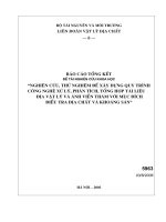
Design
Process or field communication
AS-Interface is used where individual actuators and sensors are
spaced apart over a machine (e. g. a bottle filling line, produc-
tion line, etc.).
It replaces complicated cable harnesses and connects binary
and analog actuators and sensors such as proximity switches,
valves and indicator lights to a controller, e. g. a SIMATIC or PC.
In practice this means: Installation is straightforward because
data and energy are conveyed together over one cable. No spe-
cial know-how for installation and commissioning is required.
And thanks to the simple laying of the cable, its clear-cut struc-
ture and special version there is not only far less risk of errors but
also less effort during maintenance and servicing.
Example of a system configuration
$6,QWHUIDFHGLVWULEXWRU
ZLWKRXW$6,QWHUIDFHFKLS
$6,QWHUIDFHGLVWULEXWRU
ZLWKRXW$6,QWHUIDFHFKLS
($PRGXOH
GLJLWDODQDORJ
2SHUDWRU
FRQWURO
SDQHO
6DIHVODYHZLWK
(0(5*(1&<
6723
5$
&RPSDFW
VWDUWHU
,3
$6,QWHUIDFH
SRZHUVXSSO\
6DIHW\
PRQLWRU
6LJQDO
HYDOXDWLRQ
9'&
SRZHUVXSSO\
$6L([WHQVLRQ3OXJ
IRUVHJPHQWOHQJWK
XSWRP
0D[$6LFDEOHOHQJWK
SHUVHJPHQW
PRKQH([WHQVLRQ3OXJ
PPLW([WHQVLRQ3OXJ
0D[$6LFDEOHOHQJWK
SHUVHJPHQW
PZLWKRXW([WHQVLRQ3OXJ
PZLWK([WHQVLRQ3OXJ
2QO\RQHPDVWHUFDQEH
RSWLQDOO\FRQQHFWHGWRDQ
$6LOLQH
&RPSDFWVWDUWHU
,3
$6,QWHUIDFH
SRZHUVXSSO\
5HSHDWHU
$6,QWHUIDFH0DVWHU
$6,QWHUIDFH0DVWHU
6
'3$6L)/LQN
0XOWL
3DQHO
6,0$7,&
6,027,21
/2*2
'3$6,QWHUIDFH/LQN(
6
6
6,027,21&
'3$6L/,1.$GYDQFHG
352),1(7
$6,QWHUIDFH
,QGXVWULDO(WKHUQHW
6
352),%86'3
,($6L/,1.31,2
*B,.B;;B
AS-Interface
Introduction
Communication overview
12
Siemens · 2009
■
Overview
System components
Numerous system components are offered for implementing the
communication. The key elements of a system installation are:
• Master interface modules for central control units such
as SIMATIC S5 and SIMATIC S7, distributed peripherals
• AS-Interface shaped cables
• Optional network components such as repeaters
• Power supplies for slaves, modules for connection of standard
sensors/actuators
• Actuators and sensors with integrated slave ASIC
• Safety modules for transmitting safe data through
AS-Interface
• Addressing units for setting the slave address
AS-Interface masters and AS-Interface links (see Routers)
■
Technical specifications
■
More information
For the SIMATIC NET products referred to above (order numbers
6GK , 6XV1 ) please also note the conditions of application,
which can be consulted on the Internet site quoted below.
You can find more information on the Internet at:
/>AS-Interface system manual
More information about AS-Interface is available in the
AS-Interface system manual.
The German-language AS-Interface System Manual can be
downloaded free from the Internet at:
/>The English-language AS-Interface System Manual can be
downloaded free from the Internet at:
/>A print version of the AS-Interface System Manual is also avail-
able in both German and English; see LV 1 Chapter "Systems"
> "AS-Interface" >"System components and accessories" >
"Miscellaneous accessories".
$6,QWHUIDFHPDVWHU
$6,QWHUIDFHOLQNV
&33
6,0$7,&6
6,0$7,&6
&3
,($6L/,1.31,2
'3$6L/,1.$GYDQFHG
'3$6,QWHUIDFH/LQN(
'3$6L)/LQN
6,027,21&
352),1(7
,QGXVWULDO(WKHUQHW
352),%86 $6,QWHUIDFH
&3
&33
$6,QWHUIDFH
*B,.B;;B
Standard EN 50295/IEC 61158
Topology
Line, star or tree structure (same as
electrical wiring)
Transmission medium
Unshielded two-conductor cable
(2 x 1.5 mm
2
) for data and auxiliary
power
Connection methods
Contacting of the AS-Interface
cable by insulation piercing method
Maximum cable length
100 m without repeater;
200 m with extension plug;
300 m with repeater;
600 m with repeater and
extension plug (parallel connection
of repeaters)
Maximum cycle time
5 ms with full expansion,
10 ms when using A/B technology,
profile-specific for Spec 3.0 slaves;
Number of stations per AS-Interface
line
31 slaves acc. to AS-Interface
Spec. V2.0;
62 slaves (A/B technology) acc. to
AS-Interface Spec. V2.1 and V3.0,
integrated analog value
transmission
Number of binary sensors and
actuators
Max. 124 I/124 O acc.
to Spec. V2.0;
Max. 248 I/186 O acc.
to Spec. V2.1;
Max. 496 I/496 O acc. to Spec. 3.0
Access control
Cyclic polling master slave method,
cyclic data transfer by host (PLC,
PC)
Error safeguard
Identification and repetition of faulty
message frames
AS-Interface
13
Siemens · 2009
ASIsafe
Introduction
■
Overview
Secure communication and standard communication on AS-Interface
Safety is included
The ASIsafe concept supports the direct integration of safety-
related components, such as emergency-stop switches, protec-
tive door switches or safety light arrays, in the AS-Interface net-
work. These are fully compatible with the familiar AS-Interface
components (masters, slaves, power supplies, repeaters, etc.)
according to IEC 62026/EN 50295 and are operated in conjunc-
tion with them on the yellow AS-Interface cable.
The signals of the safety sensors are evaluated by a safety mon-
itor which not only monitors the switching signals of the safety
sensors but also continuously checks that the data transmission
works correctly. The safety monitor has one or two enabling cir-
cuits which are configured with two channels and are used to
switch the machine or plant to the safe state. Sensors and mon-
itors can be connected to any points of the AS-Interface network.
Also, several monitors can be used on one network.
A failsafe controller or a special master is not required. The mas-
ter regards safety slaves like all other slaves and receives the
safety data solely for information purposes. Hence it is also pos-
sible to expand all existing AS-Interface networks.
ASIsafe ensures a maximum response time of 40 ms. This is the
time between the signal being applied to the input of the safe
slave and the output on the safety monitor being switched off.
Tested safety
The system was tested and approved by TÜV (Germany), NRTL
(USA) and INRS (France). The transmission procedure for
safety-oriented signals is configured for implementing applica-
tions up to Category 4 according to EN 954-1, up to PL e accord-
ing to EN ISO 13849-1 and up to SIL 3 according to IEC 61508.
Software
With the asimon configuration software you can compile safety-
oriented applications and transfer them into the monitor. The
software also enables online diagnostics.
Standard PLC
Standard-Master
Standard-
Slave
Safety monitor
Safe slave with
EMERGENCY
STOP
Power
supply unit
Signal evaluation of slave/safety monitor
AS-i POWER
AS-Interface
NSA0_00005d
AS-Interface
ASIsafe
Introduction
14
Siemens · 2009
■
Design
The design of the safety systems is identical to the wiring of
AS-Interface as it is known today.
The family of safe AS-Interface products comprises the safety
monitor which monitors the safe stations. The range of safe sta-
tions comprises the safety modules and the safety-related sen-
sors with integrated interface.
■
Function
Like the standard stations, the safe stations send their informa-
tion to the master after master calls. The safety monitor monitors
this transmission from the safe stations to the master and
switches into the safe state.
The safety monitor is configured with the software "asimon". The
configuration comprises the input signals of the safe stations
and the internal functions of the safety monitor. The safety mon-
itor provides OR logic, AND logic, timer functions, buffer
storage, etc.
■
Integration
The existing infrastructure such as the master and the power
supply unit can be used as before for integrating the safety sys-
tems in AS-Interface. For the safety systems the safety monitor
is integrated as monitoring element and the safe stations as in-
terface between the safe sensors and the system. The safe sen-
sors can be used as before.
Integration within TIA is performed using function blocks which
are offered on the ASIsafe CD-ROM for S7-200 and S7-300.
These function blocks enable detailed diagnostics of all param-
eterized modules. This requires an AS-i address to be issued to
the safety monitor by means of the configuration software. Eval-
uation is performed by means of function blocks in the PLC. With
the help of prefabricated WinCC flexible modules this evaluation
can then be visualized system-wide on existing HMI devices
(OP/TP 270 and higher).
Standard PLC and
standard AS-i master:
Central installation at the
PLC and distributed
installation using
DP-AS-i Links is possible.
Safety monitor:
The safety monitor evaluates
all safe inputs and ensures
safe disconnection.
Safe slave:
Safe signals are recorded
by the safe slaves.
Standard AS-i slaves:
Standard and
safety-oriented slaves
can be connected to one bus.
The components of ASIsafe
Safety monitor Safe slave
Signal evaluation safe slave/safety monitor
AS-Interface cable
Extended ASIsafe diagnostics (through regular I/O transfer)
Standard PLC and
standard master
Standard AS-i
power supply unit
Standard slave Standard slave Standard slave
NSB0_01509
AS-Interface
15
Siemens · 2009
ASIsafe
AS-Interface safety monitors
■
Overview
Safety monitor with screw terminals (removable terminals)
The safety monitor is the centerpiece of ASIsafe Solution local. It
enables safety-orientated responding to signals from the
ASIsafe (input) slaves on the same AS-i network and has
1-2 enabling circuits. A safe application is configured using a
PC. Various application-specific operating modes can be se-
lected for this. They include, for example, an EMERGENCY-
STOP function, door tumbler and selection of stop Category 0 or
Category 1.
To be able to make full use of the AS-Interface diagnostics op-
tions, the monitor can also be operated with an AS interface ad-
dress if required. With the help of the diagnostics module for
STEP 7, which is included on the ASIsafe CD, the full diagnostics
spectrum can be processed further in the higher-level PLC.
The AS-Interface safety monitor is currently offered in the latest
Version 3 (Firmware V3.x) and is available in three expansion
levels.
Both basic/expanded expansion levels are available with one or
two-channeled configured enabling circuits.
The expanded safety monitor is also available as a version with
integrated safe slave which can be used for the control of a safe
AS-i output or for safe coupling of a switch signal on another
safety monitor or F-Link.
The safety monitor is used in an AS-Interface bus system to mon-
itor protective devices, e. g. protective doors, EMERGENCY-
STOP switches, etc.
The safety monitor can be used up to Category 4 acc. to
EN 954-1, to PL e acc. to EN ISO 13849-1 and to SIL 3 acc. to
IEC 61508.
The safety characteristics for the maximum service life (T1) of 20
years are:
• PFD: 7.2 x 10
-5
(monitor type 1, 2, 3, 4)
esp. 6.1 x 10
-5
(monitor type 6)
• PFH D: 7.2 x 10
-5
(all monitor types)
The user must calculate the PFD value of the total loop.
Note:
Depending on the choice of safety components used, the com-
plete safety system may also be classified in a lower safety
category.
The safety monitor is mounted on the standard mounting rail.
Disassembly from the standard mounting rail is quick and easy
and requires no tools. With an additional accessory (push-in
lugs), the safety monitor can also be screwed on.
■
Application
The safety monitor acts as a "bus-based safety relay". It provides
a user-friendly introduction to safety-orientated communication
over fieldbuses thanks to its simple configuration using the
graphic PC software asimon. The standard infrastructure of the
AS-i network (AS-i master under standard PLC, AS-i power sup-
ply unit) can still be used without restriction.
The monitor comes in three expansion levels:
• Basic safety monitor
with starter set of modules and basic functionality
• Expanded safety monitor with expanded features and
functionality
• The expanded safety monitor is also available as a version
with integrated safe slave which can be used for the control of
a distributed safe AS-i output or for safe coupling of a switch
signal on another safety monitor or F-Link.
Basic safety monitor versus expanded safety monitor
✓ Available
Not available
Number of monitoring modules
The number of devices which the safety monitor can process is
increased with the expanded safety monitor from 32 to 48. Ap-
plications of greater complexity and size can thus be simulated
in the safety monitor.
Logic OR operation
At the logic operation level two elements can be linked by OR
operations in the basic version and up to six in the expanded
version.
Logic AND operation
In addition to the standard AND operation in the main path of an
enabling circuit, an AND operation can also be inserted in an OR
operation on the expanded safety monitor. More than two ele-
ments can be linked in this AND.
Basic Expanded
Number of monitoring modules
32 48
Number of OR gates (inputs)
2 6
Number of AND gates (inputs)
6
Wildcards for monitoring modules
✓ ✓
Deactivating of monitoring modules
✓ ✓
Fault release
✓ ✓
Diagnostics hold
✓ ✓
A/B slaves for acknowledgment
✓ ✓
Safe time functions
✓
"Button" function
✓
Debouncing of contacts
✓
Filtering out of brief disconnections
✓ (as of Version 3)
Control of safe AS-i output/safe coupling
✓ (in version with
integrated safe
slave)
AS-Interface
ASIsafe
AS-Interface safety monitors
16
Siemens · 2009
Features of the basic safety monitor
• Wildcards and deactivating of monitoring modules
Wildcards are available for the configuration. They are inte-
grated in the configuration and diagnostics and can be easily
activated if required. User-friendly configuring is thus possible
even when system configurations change.
• Fault release:
If a module detects a fault, the AS-Interface safety monitor
goes into fault status. A differentiated fault release (reset) is
now possible for this scenario. The fault release can be acti-
vated by an AS-Interface standard slave, e. g. a pushbutton,
and is effective only on module level. The great advantage of
this is that the entire safety monitor is no longer reset but only
the module which is locked in the fault.
• Diagnostics hold:
Disconnections can be "frozen" until an acknowledgment
comes through a standard slave. This function provides valu-
able help in the event of short-time causes of disconnection.
• Also from Version 3 upwards:
The standard output data bits of safe input slaves can be pro-
cessed for acknowledgment, fault release and other non-
safety-oriented signals.
Additional features of the expanded safety monitor
The following additional features are provided by only the ex-
panded safety monitor:
• Safe time functions:
Timers with the following functions are available:
-ON-delay
- OFF-delay and
-Pulse
• "Button" function:
Additional acknowledgment option for restarting the system
using an additional button. The button function can be as-
signed to any input or output signal of a standard slave
through configuration in the asimon software.
• Debouncing of contacts:
For debouncing the contacts it is possible to set a bounce
time after which a system restart takes place.
• Also from Version 3 upwards:
Filtering out of brief single-channel interruptions in the sensor
circuit. A tolerance time can be set during which the brief
opening of a safety-oriented input contact is ignored in order
to increase plant availability.
Additional features of the expanded safety monitor with inte-
grated safe slave
This new safety monitor type offers the additional features of the
expanded safety monitor plus the following features:
• Filtering out of brief single-channel interruptions in the sensor
circuit.
• Actuating a safe distributed actuator (safe output module of
e. g. safe valves or motor starters) parallel to the 2nd enabling
circuit.
• Alternatively: Use as a "safe coupler" between two ASIsafe
networks. A safe input signal on network 1 can thus act on an
enabling circuit of network 2. A detour through a hard-wired
safe input module on network 2 is not required in this case.
Configuration software asimon V3: new features
• Multi-window system
• Creation of the safety logic in graphic function diagram form,
with changeover to former tree presentation possible
• No "preprocessing" of the safety logic
• Management of user-specific modules
• Downward compatibility:
- Existing asimon V2 projects can be loaded
- Can also be used on all former versions of the safety monitor
- with the corresponding scope of functions
• Graphic printout of the safety logic
• Easier system start-up:
- Teaching the code sequences of safe
AS-Interface slaves
- Manual input of code sequences also possible in addition
- Selectable number of simulated slaves
• Simpler diagnostics using AS-Interface through assignment of
a diagnostics index to the software function block
• Signaling the switching state of the signaling and relay outputs
to higher-level PLCs using a simulated AS-Interface slave
• New functions for filtering out brief interruptions and for con-
trolling a safe AS-i output or for safe coupling of two AS-i
networks
Interface of the configuration software asimon V3
AS-Interface
17
Siemens · 2009
ASIsafe
AS-Interface safety monitors
■
Technical specifications
3RK1 105 safety monitor
■
Dimensional drawings
Safety monitor
■
Schematics
The protective conductor must be connected to the FE connec-
tion if the terminal M is not connected to ground in the direct
vicinity of the unit.
Safety monitor type 1, type 3 – with one enabling circuit
Safety monitor type 2, type 4, type 6 – with two enabling circuits
(terminals AS-iS+/AS-iS- only for type 6)
Rated operational current
I
e
/AC-12 up to 250 V A 3
I
e
/AC-15
• 115 V
• 230 V
A
A
3
3
I
e
/DC-12 up to 24 V A 3
I
e
/DC-13
• 24 V
• 115 V
• 230 V
A
A
A
1
0.1
0.05
Response time ms
≤ 40
Achievable performance level
acc. to EN ISO 13849-1
PL e
Achievable SIL (or SILCL) acc. to
EN 62061
SIL 3
Failure probability (PFH
D
) acc. to
EN 62061
For max. service life (T1) of 20 years 9.1 x10
-9
Failure probability (PFD) acc. to
EN 61062
7.2 x 10
-5
(monitor type 1, 2, 3, 4)
esp. 6.1 x 10
-5
(monitor type 6)
Ambient temperature °C
0 +60
Storage temperature °C
-40 +85
NSA00073b
102
120
45
5
NSA0_00356
M
N / M
1.32
Q1
1.14 1.24
Q2
L+ M
FE
1
2
3
AS-i
1.Y1
1.Y2
AS-i-
1.13
AS-i+
1.23
Start 1
Q1
Q2
L+ 24 V DC
L / L+
Q2
Q1
M
1.Y1
L+
NSA0_00475
M
N / M
1.32
Q1
1.14 1.24
Q2
L+ M
Q3
2.242.14
FE
Q4
2.32
1
2
3
AS-i
1
2
3
AS-iS
1.Y1 2.13 2.23 2.Y1
1.Y2 +AS-iS- 2.Y2
AS-i-
1.13
AS-i+
1.23
Start 1 Start 2
Q1
Q2
Q4
Q3
L+ 24 V DC
L / L+
+AS-iS-
Q4
Q3
M
Q2
Q1
M
1.Y1
L+
2.Y1
L+
AS-Interface
ASIsafe
AS-Interface safety modules
18
Siemens · 2009
■
Overview
Safety modules for AS-Interface (ASIsafe modules) are available
for field use in degree of protection IP67 (K20F and K45F com-
pact modules) and for the control cabinet (S22.5F SlimLine
modules) in degree of protection IP20.
A very compact module with an optimum price /performance
ratio is thus available for very application.
Following modules are available for selection:
K20F compact safety modules for operation in the field
Being only 20 mm wide, the K20F module is particularly well
suited for applications where modules need to be arranged in
the most confined space. The K20F modules are connected to
the AS-Interface with a round cable with M12 cable box instead
of with the AS-Interface flat cable. This enables extremely com-
pact installation. The flexibility of the round cable means that it
can also be used on moving machine parts without any prob-
lems. The K20 modules are also ideal for such applications as
their non-encapsulated design makes them particularly light in
weight.
K45F compact safety modules for operation in the field
The platform of the K45F modules covers the following
variations:
• Connection of ("mechanical") switches/safety sensors with
contacts:
- K45F 2F-DI: two safety-oriented inputs in operation up to
Category 2 according to EN 954-1. If Category 4 is required,
a two-channel input is available on the module.
- K45F 2F-DI/2DO: There are also two standard outputs in ad-
dition to the safe inputs. Supplied from the yellow AS-i cable
- K45F 2F-DI/2DO U
aux
: same as K45F 2F-DI/2DO, but sup-
plied from the black 24 V DC cable
- K45F 4F-DI: four safety-oriented inputs in operation up to
Category 2, two for Category 4. Extremely compact double
slave (uses two full AS-i addresses).
• Connection of solid-state switches/safety sensors
(non-contact protective devices, BWS):
- K45F LS (light sensor): safe input module for connection of
solid-state safety sensors with testing semiconductor out-
puts (OSSD). In particular non-contact protective devices
(BWS) such as active, optoelectronic light arrays and light
curtains for Type 2 and Type 4 according to IEC/EN 61496.
Transmitters as well as receivers are supplied with power
from the yellow AS-i cable. Matching sensor cables and op-
tionally a separate transmitter supply module are available
as accessories.
S22.5F SlimLine safety modules for operation in
control cabinets and local control cabinets
The S22.5F SlimLine safety module has two safety inputs. The
safe connection of signals to ASIsafe networks in the control
cabinet is also possible therefore. For operation up to Category
2, both inputs can be assigned separately; if Category 4 is re-
quired, a two-channel input is available on the module.
In addition there are two S22.5F module versions which have two
standard outputs in addition to the two safety inputs; power is
supplied either from only the yellow AS-Interface cable or as
auxiliary voltage from the black 24 V DC cable.
AS-Interface
19
Siemens · 2009
ASIsafe
AS-Interface safety modules
■
Technical specifications
K20F compact
safety modules
K45F compact safety modules
2 inputs, safe 2 inputs, safe 4 inputs, safe 2 inputs, safe 2 inputs, safe 2 inputs, safe, BWS for
1 light curtain
2 outputs,
standard
2 outputs,
standard with U
aux
2 F-DI 2 F-DI 4 F-DI 2 F-DI/2 DO 2 F-DI/2 DO with
U
aux
2 F-DI (solid-state,
LS - light sensor)
3RK1 205-0BQ30-
0AA3
3RK1 205-0BQ00-
0AA3
3RK1 205-
0CQ00-0AA3
3RK1 405-0BQ20-
0AA3
3RK1 405-1BQ20-
0AA3
3RK1 205-0BQ21-0AA3
LS type 2
3RK1 205-0BQ24-0AA3
LS type 4
I/O configuration
0 7 0
ID/ID2 code
B/0 B/F B/F B/1
PFD value
Makes no notable contribution to the PFD of the overall system, comprised of the AS-Interface bus and safety monitor
Operational voltage
acc. to AS-Interface
specification
V
26.5 31.5 26.5 31.5
Total current input mA
≤ 45 ≤ 70 ≤ 250 ≤ 60 ≤ 60
Inputs
• Sensors Mechanical switching contact Mechanical switching contact Testing semiconductor
outputs (OSSD)
• Input current High mA
I
peak
≥ 5 I
peak
≥ 5
Assignment of inputs
• Pin 1 and Pin 2: Connection/switching contact
• Pin 3 and Pin 4: Connection/switching contact
• Pin 5: Not assigned
• Pin 1 and Pin 2: Connection/switch-
ing contact
• Pin 3 and Pin 4: Connection/switch-
ing contact
• Pin 5: Not assigned
• Type 2 receiver:
Pin 1/4/7: -
Pin 2/3: +
Pin 5: CH1
Pin 6: CH2
Pin 8: FE
• Type 4 receiver:
Pin 1/4 diag
Pin 2/3: +
Pin 5: CH1
Pin 6: CH2
Pin 7: -
Pin 8: FE
• Type 2/4, alternative
receiver (5-pole):
Pin 1: +
Pin 2: CH2
Pin 3: -
Pin 4: CH1
Pin 5: FE
• Type 2/4 transmitter:
Pin 1/4: +
Pin 3: -
Pin 5: FE
Outputs
• Type of output Solid-state
• Current carrying capacity
per output DC 12/13
typical
A
0.15 0.7
• Maximum summation
current per module
A
0.15 1.4
• Socket assignment of
outputs
• Pin 3: "-"
• Pin 4: Output
• Pin 5: Not assigned
• Short-circuit protection
Built-in
• Induction protection
Built-in
• External power supply
24 V DC
Using black
AS-Interface flat
cable
• Watchdog
Built-in
Assignment of outputs
• OUT 1 (D0) Socket 3 - Pin 4
Socket 4 - Pin 4
• OUT 2 (D1)
AS-Interface certificate
Yes Yes
AS-Interface
ASIsafe
AS-Interface safety modules
20
Siemens · 2009
K20F compact
safety modules
K45F compact safety modules
2 inputs, safe 2 inputs, safe 4 inputs, safe 2 inputs, safe 2 inputs, safe 2 inputs, safe, BWS for
1 light curtain
2 outputs,
standard
2 outputs,
standard with U
aux
2 F-DI 2 F-DI 4 F-DI 2 F-DI/2 DO 2 F-DI/2 DO with
U
aux
2 F-DI (solid-state,
LS - light sensor)
3RK1 205-0BQ30-
0AA3
3RK1 205-0BQ00-
0AA3
3RK1 205-
0BQ00-0AA3
3RK1 405-0BQ20-
0AA3
3RK1 405-1BQ20-
0AA3
3RK1 205-0BQ21-0AA3
LS type 2
3RK1 205-0BQ24-0AA3
LS type 4
Approvals
UL, CSA under
application
UL, CSA UL, CSA
Degree of protection
IP65/67 IP65/67
Ground terminal
Pin 5 or 8:
Sensor grounding
FE: Grounding lug
Ambient temperature °C
-25 +70 -25 +70
Storage temperature °C
-40 +85 -40 +85
Number of I/O sockets
2 4 2
Transmitter to bottom right
socket,
receiver (8-pole) to top
right socket
(Siemens 3RG7843/46),
receiver (5-pole) to top left
socket
Status displays
• Display of I/Os Yellow LED Yellow LED
• U
aux
Not required Not required Green LED Not required
• Display of AS-Interface/
diagnostics
Green/red LED Green/red LED
Connection
Using M12 feeder Using mounting plate for
K45 compact module
Using mounting plate for K45 compact module
S22.5F SlimLine safety module, with screw-type or spring-type terminal
2 inputs, safe
2 outputs, standard 2 outputs, standard with U
aux
2 F-DI 2 F-DI/2 DO 2 F-DI/2 DO with U
aux
•Screw
terminals
3RK1 205-0BE00-0AA2 3RK1 405-0BE00-0AA2 3RK1 405-1BE00-0AA2
• Spring-type
terminals
3RK1 205-0BG00-0AA2 3RK1 405-0BG00-0AA2 3RK1 405-1BG00-0AA2
I/O configuration
0 7 7
ID/ID2 code
B/F B/F B/F
PFD value
Makes no notable contribution to the
PFD of the overall system, comprised of
the AS-Interface bus and safety monitor
Makes no notable contribution to the
PFD of the overall system, comprised of
the AS-Interface bus and safety monitor
Makes no notable contribution to the
PFD of the overall system, comprised of
the AS-Interface bus and safety monitor
Operational voltage
according to AS-Interface
specification
V
26.5 31.5 26.5 31.5 26.5 31.5
Total current input mA
≤ 45 ≤ 250 ≤ 60
Inputs
•Sensors Mechanical switching contact Mechanical switching contact Mechanical switching contact
• Input current Low mA
Contact open Contact open Contact open
• Input current High mA
Contact closed
I
peak
≥ 5
Contact closed
I
peak
≥ 5
Contact closed
I
peak
≥ 5
Assignment of inputs
• F-IN1.1 and F-IN1.2: Connection of
switching contact
• F-IN2.1 and F-IN2.2: Connection of
switching contact
• F-IN1.1 and F-IN1.2: Connection of
switching contact
• F-IN2.1 and F-IN2.2: Connection of
switching contact
• F-IN1.1 and F-IN1.2: Connection of
switching contact
• F-IN2.1 and F-IN2.2: Connection of
switching contact
AS-Interface
21
Siemens · 2009
ASIsafe
AS-Interface safety modules
■
Dimensional drawings
K20 module, two safe inputs, M12 (3RK1 205-0BQ30-0AA3)
K45F compact safe module:
3RK1 205-0BQ00-0AA3, 3RK1 205-0CQ00-0AA3,
3RK1 405-0BQ20-0AA3, 3RK1 405-1BQ20-0AA3,
3RK1 205-0BQ21-0AA3, 3RK1 205-0BQ24-0AA3
S22.5F SlimLine safety module, with screw-type or spring-type terminal
2 inputs, safe
2 outputs, standard 2 outputs, standard with U
aux
2 F-DI 2 F-DI/2 DO 2 F-DI/2 DO with U
aux
Screw terminals 3RK1 205-0BE00-0AA2 3RK1 405-0BE00-0AA2 3RK1 405-1BE00-0AA2
Spring-type
terminals
3RK1 205-0BG00-0AA2 3RK1 405-0BG00-0AA2 3RK1 405-1BG00-0AA2
Outputs
• Type of output Solid-state Solid-state
• Current carrying capacity
per output DC 12/13
typical
A
0.15 0.7
• Maximum summation
current per module
A
Max. 0.15 Max. 1.4
• Short-circuit protection
Built-in Built-in
• Induction protection
Built-in Built-in
• External power supply
24 V DC
Using black AS-Interface flat cable
• Watchdog
Built-in Built-in
• Wiring of outputs
See section Schematics/Wiring –
SlimLine Safety Module S22.5F
See section Schematics/Wiring –
SlimLine Safety Module S22.5F
• Assignment of outputs
-OUT 1 D0 D0
-OUT 2
D1 D1
AS-Interface certificate
Yes Under application Under application
Approvals
UL, CSA UL, CSA UL, CSA
Mechanical specifications
• Degree of protection IP20 IP20 IP20
• Shock load
(IEC 60068-2-6)
g/
ms
15/11 15/11 15/11
• Vibratory load
(IEC 60068-2-27)
Hz
Hz
Hz
5 500
5 26: 0.75 mm amplitude
26 500: 2 g
5 500
5 26: 0.75 mm amplitude
26 500: 2 g
5 500
5 26: 0.75 mm amplitude
26 500: 2 g
Ground terminal
Ambient temperature °C
-25 +70 -25 +70 -25 +70
Storage temperature °C
-40 +85 -40 +85 -40 +85
Number of I/O sockets
Status displays
• Display of I/Os Yellow LED Yellow LED Yellow LED
• U
aux
Green LED
• Display of AS-Interface/
diagnostics
Green/red LED Green/red LED Green/red LED
Connection
Using screw terminals or
spring-type terminals
Using screw terminals or
spring-type terminals
Using screw terminals or
spring-type terminals
20 20
36
45
NSA0_00438
100
108
Ø
4,6
NSB0_01872
80
45 30 34
AS-Interface
ASIsafe
AS-Interface safety modules
22
Siemens · 2009
S22.5F SlimLine safety module, 2 F-DI, screw terminals
3RK1 205-0BE00-0AA2
S22.5F SlimLine safety module, 2 F-DI/2 DO, screw terminals
3RK1 405-0BE00-0AA2 (without U
aux
)
3RK1 405-1BE00-0AA2 (with U
aux
)
S22.5F SlimLine safety module, 2 F-DI, spring-type terminals
3RK1 205-0BG00-0AA2
S22.5F SlimLine safety module, 2 F-DI/2 DO, spring-type terminals
3RK1 405-0BG00-0AA2 (without U
aux
)
3RK1 405-1BG00-0AA2 (with U
aux
)
■
Schematics
Logical assignments - K45F compact safety module
If only a single-channel switch is to be connected to the module,
it must be connected to Channel 1. The second channel must be
bridged. This is done with the M12 plug 3RK1 901-1AA00 at
socket 2.
Pin 3 of socket 1 is connected to Pin 1 of socket 2, and Pin 4 of
socket 1 is connected to Pin 2 of socket 2. If both pairs of
sockets are assigned, the inputs are linked.
Logical assignments - K45F LS compact safety module
8 0
9 0
7 3 , 5
3 2
6 0
8 6
5
N S A 0 _ 0 0 4 2 2
1 5
2 2 , 5
6 2
7 2
1 1 0
8 2 , 6
9 2 , 2
7 3 , 5
6
3 6
6 5
8 6
5
N S A 0 _ 0 0 4 2 3
1 5
2 2 , 5
6 8 , 2
8 7 , 2
1 1 0
7 , 2
1 0 1 , 6
2 8 , 8
15
22,5
71
81
110
80
90
73,5
86
5
NSA0_00424
8 4 , 4
9 3 , 9
7 3 , 5
8 6
5
1 0 3 , 4
2 8 , 8
1 5
2 2 , 5
7 5 , 1
9 4 , 1
1 1 0
2 , 5
7 , 2
N S A 0 _ 0 0 4 2 5
7 , 2
N S A 0 _ 0 0 3 5 5 a
1
ADDR
4
3
2
1
3
4
2
1
S o c k e t
P i n 1 a n d P i n 2 : I n f l u e n c e s t h e b i t s D 0 a n d D 1 = C h a n n e l 1
P i n 3 a n d P i n 4 : I n f l u e n c e s t h e b i t s D 2 a n d D 3 = C h a n n e l 2
P i n 5 n o t a s s i g n e d
A s s i g n m e n t / d a t a s h e e t s / f u n c t i o n
P i n 1 a n d P i n 2 : I n f l u e n c e s t h e b i t s D 2 a n d D 3 = C h a n n e l 2
P i n 5 n o t a s s i g n e d
N o t a s s i g n e d
N o t a s s i g n e d
2
3
4
Socket Assignment/data sheets/function
1
2
1
2
Type 2 receiver:
Pin 1/4/7: -
Pin 2/3: +
Pin 5: CH1
Pin 6: CH2
Pin 8: FE
Type 4 receiver:
Pin 1/4 Diag
Pin 2/3: +
Pin 5: CH1
Pin 6: CH2
Pin 7: -
Pin 8: FE
Type 2/4, alternatively receiver (5-pole):
Pin 1: +
Pin 2: CH2
Pin 3: -
Pin 4: CH1
Pin 5: FE
Type 2/4 transmitter:
Pin 1/4: +
Pin 3: -
Pin 5: FE
NSB_01919
ADDR.
2
3
3
4
4
1
5
5
2
6
7
1
8
AS-Interface
23
Siemens · 2009
ASIsafe
AS-Interface safety modules
Logical assignments - K20F compact safety module
If only a single-channel switch is to be connected to the module,
it must be connected to Channel 1. The second channel must be
bridged. This is done with the M12 plug 3RK1 901-1AA00 at
socket 2.
Pin 3 of socket 1 is connected to Pin 1 of socket 2, and Pin 4 of
socket 1 is connected to Pin 2 of socket 2. If both pairs of sock-
ets are assigned, the inputs are linked.
Wiring – S22.5F SlimLine safety module
Wiring for S22.5F SlimLine safety module, 2F-DI, Category 2 (right) and
Category 3/4 (left)
3RK1 205-0BE00-0AA2 (screw terminals)
3RK1 205-0BG00-0AA2 (spring-type terminals)
Wiring for S22.5F SlimLine safety module, 2F-DI/2 DO without U
aux
,
Category 2 (right) and Category 3/4 (left)
3RK1 405-0BE00-0AA2 (screw terminals)
3RK1 405-0BG00-0AA2 (spring-type terminals)
Wiring for S22.5F SlimLine safety module, 2F-DI/2 DO with U
aux
,
Category 2 (right) and Category 3/4 (left)
3RK1 405-1BE00-0AA2 (screw terminals)
3RK1 405-1BG00-0AA2 (spring-type terminals)
1
3
4
2
NSA0_00442a
Socket Assignment / data sheets / function
1 Pin 1 and Pin 2: Influences the bits D0 and D1 = Channel 1
Pin 3 and Pin 4: Influences the bits D2 and D3 = Channel 2
Pin 5 not assigned
2 Pin 1 and Pin 2: Influences the bits D2 and D3 = Channel 2
Pin 3, Pin 4 and Pin 5 not assigned
Socket 1
Socket 2
AS-i+
AS-i– F-IN1.2
ADDR.
987
32
1
AS-i
F-IN1
F-IN2
65
4
F-IN2.2
F-IN1.1 F-IN2.1
AS-i+
AS-i– F-IN1.2
ADDR.
987
32
1
AS-i
F-IN1
F-IN2
65
4
F-IN2.2
S1
F-IN1.1 F-IN 2.1
S1
S2
NSA0_00426
+
AS-i+
AS-i– F-IN1.2
ADDR.
987
32
1
AS-i
F-IN1
F-IN2
OUT1 OUT2
65
4
F-IN2.2
S1
F-IN1.1 F-IN2.1
S2
121110
MM
OUT1
OUT2
+
AS-i+
AS-i– F-IN1.2
ADDR.
987
32
1
AS-i
F-IN1
F-IN2
OUT1 OUT2
65
4
F-IN2.2
S1
F-IN1.1 F-IN2.1
121110
MM
OUT1
OUT2
NSA0_00427
+
AS-i+
AS-i– F-IN1.2
ADDR.
987
32
1
AS-i
F-IN1
F-IN2
OUT1 OUT2
65
4
F-IN2.2
S1
F-IN1.1 F -IN2.1
L+
S2
121110
MMM
OUT1
OUT2
+
+
_
AS-i+
AS-i– F-IN1.2
ADDR.
987
32
1
AS-i
F-IN1
F-IN2
OUT1 OUT2
65
4
F-IN2.2
S1
F-IN1.1 F-IN2.1
L+
121110
MMM
OUT1
OUT2
+
_
NSA0_00428
AS-Interface
ASIsafe
CP 243-2
24
Siemens · 2009
■
Overview
The CP 243-2 is the AS-Interface master for the SIMATIC S7-200.
This communications processor (6GK1 243-2AX01-0AX0) sup-
ports the extended AS-Interface specification V2.1 and per-
forms the following functions:
• Connection of up to 62 AS-Interface slaves and integrated an-
alog value transmission (according to the extended
AS-Interface specification V2.1)
• Supports all AS-Interface master functions according to the
extended AS-Interface specification V2.1
• Status displays of operating states and indication of the read-
iness for operation of connected slaves by means of LEDs in
the front panel
• Fault indications (e. g. AS-Interface voltage fault, configura-
tion fault) by means of LEDs in the front panel
• Compact enclosure in the design of the SIMATIC S7-200
■
Design
The CP 243-2 is connected like an expansion module to the
S7-200. It has:
• Two terminal connections for direct connection of the
AS-Interface cable
• LEDs in the front panel for indicating the operating state and
functional readiness of all connected and activated slaves
• Two pushbuttons for indicating the status information of the
slaves, for switching over the operating state and for adopting
the existing ACTUAL configuration as the DESIRED
configuration.
■
Function
The CP 243-2 supports all specified functions of the extended
AS-Interface specification V2.1. This means that up to 62 digital
or 31 analog slaves can be operated on the AS-Interface
through expanded addressing (A/B).
Thanks to the integrated analog value processing it is just as
easy to access the analog values as the digital values.
In the process image of the S7-200 the CP 243-2 occupies one
digital input byte (status byte), one digital output byte (control
byte), and 8 analog input and 8 analog output words. The
CP 243-2 thus occupies two (logic) slots. The operating mode of
the CP 243-2 can be set with the status byte and the control byte
using the user program.
Depending on the operating mode the CP 243-2 saves either the
digital or analog I/O data of the AS-Interface slaves or diagnostic
values in the analog address area of the S7-200, or it enables
master calls (e. g. re-addressing of the slaves).
Configuration
All connected AS-Interface slaves are configured at the press of
a button. No further configuration of the CP is required.
■
Technical specifications
AS-Interface specification V 2.1
Bus cycle time
ms 5 with 31 slaves
10 with 62 slaves
Interfaces
• Assignment of address area
in AG
16 bytes AE/AA, 1 byte DE/DA
• AS-Interface connection
Screw terminals
Power consumption
• Using backplane bus mA Max. 220 at 5 V DC
• From AS-Interface cable
mA Max. 100
Power loss
W Approx. 2
Permissible ambient conditions
• Operating temperature
- Horizontal installation °C 0 +55
- Vertical installation
°C 0 +45
• Transport/storage temperature
°C - 40 +70
• Relative humidity
% Max. 95 at +25 °C
Structural design
• Module format S7-22x expansion module
• Dimensions (W x H x D)
mm 71 x 80 x 62 (H+16 mm with holes
for wall mounting)
•Weight
g 250
• Space requirement
1 mounting space
AS-Interface
25
Siemens · 2009
ASIsafe
CP 343-2
■
Overview
The CP 343-2 is the AS-Interface master for the SIMATIC S7-300
programmable controller and the ET 200M distributed I/O sta-
tion. The communications processor performs the following
functions:
• Connection of up to 62 AS-Interface slaves and integrated an-
alog value transmission (according to the AS-Interface
Specification V3.0)
• Supports all AS-Interface master functions according to the
AS-Interface Specification V3.0
• Status displays of operating states and indication of the read-
iness for operation of connected slaves by means of LEDs in
the front panel
• Fault indications (e. g. AS-Interface voltage fault, configura-
tion fault) by means of LEDs in the front panel
■
Design
The CP 343-2 is connected like an expansion module to the
S7-300. It has:
• Two terminal connections for direct connection of the
AS-Interface cable
• LEDs in the front panel for indicating the operating state and
functional readiness of all connected and activated slaves
• Pushbuttons for indicating the status information of the slaves,
for switching over the operating state and for adopting the ex-
isting ACTUAL configuration as the DESIRED configuration.
■
Function
The CP 343-2 supports all specified functions of the
AS-Interface specification V3.0. This means that up to 62 digital
or analog slaves can be operated on the AS-Interface through
expanded addressing (A/B). The integrated analog value pro-
cessing permits easy access to the analog values.
The CP 343-2 occupies 16 bytes each in the I/O address area of
the SIMATIC S7-300. The digital I/O data of the standard slaves
and A slaves are saved in this area. The digital I/O data of the B
slaves and the analog I/O data can be accessed with the S7 sys-
tem functions for read/write data record. A slaves and B slaves
are slaves according to AS-Interface Specification V2.1
and V3.0.
If required, master calls can be performed with the command in-
terface FC ASI_3422, e. g. read/write parameters, read/write
configuration.
The FC including a STEP7 sample program can be downloaded
from the Internet at
/>.
Configuration
All connected AS-Interface slaves are configured at the press of
a button. No further configuration of the CP is required.
■
Technical specifications
AS-Interface specification V3.0
Bus cycle time
ms 5 with 31 slaves
10 with 62 slaves
Interfaces
• Assignment of address area in
AG
16 bytes I/O
• AS-Interface connection
S7-300 front connector with
terminal connection
Supply voltage
V DC +5, using backplane bus
Power consumption
• From backplane bus mA Max. 200 at 5 V DC
• From AS-Interface cable
mA Max. 100
Power loss
W 2
Permissible ambient conditions
• Operating temperature °C 0 +60
• Transport/storage temperature
°C -40 +70
• Relative humidity, max.
% 95 at +25 °C
Structural design
• Module format S7-300 design
• Dimensions (W x H x D)
mm 40 x 125 x 120
•Weight
g 190
• Space requirement
1 mounting space