TÀI LIỆU HƯỚNG DẪN SỬ DỤNG LOGO RC230 TIẾNG ANH
Bạn đang xem bản rút gọn của tài liệu. Xem và tải ngay bản đầy đủ của tài liệu tại đây (2.38 MB, 336 trang )
Preface, Contents
Getting started with LOGO!
1
LOGO! installation and wiring
2
Programming LOGO!
3
LOGO! functions
4
Configuring LOGO!
5
LOGO! program module (card)
6
LOGO! Software
7
Applications
8
Technical data
A
Determining the cycle time
B
LOGO! without display
C
LOGO! menu structure
D
Order numbers
E
Abbreviations
F
Index
LOGO!
Manual
Edition 05/2006
A5E00380835-02
This manual has
the or der number:
6ED1050-1AA00-0BE6
Safety Guidelines
This manual contains notices you have to observe in order to ensure your personal safety, as well as to prevent
damage to property. The notices referring to your personal safety are highlighted in the manual by a safety alert
symbol; notices referring to property damage only have no safety alert symbol. The notices shown below are graded
according to the degree of danger.
!
Danger
indic ates that death or severe personal injury will result if proper precautions are not tak en.
!
Warning
indic ates that death or severe personal injury may result if proper precautions are not taken.
!
Caution
with a safety alert symbol indicates that minor personal injury can result if proper precautions are not taken.
Caution
without a safety alert symbol indicates that property damage can result if proper precautions are not taken.
Attention
indic ates that an unintended result or situation can occur if the corresponding notice is not taken into account.
If more than one degree of danger is present, the warning notice representing the highest degree of danger will be
used. A notice warning of injury to persons with a safety alert symbol may also include a warning relating to property
damage.
Qualified Personnel
The device/system may only be set up and used in conjunction with this documentation. Commissioning and
operation of a device/system may only be performed by qualified personnel. Withi n the contex t of the safety notices
in this documentation qualified persons are defined as persons who are authorized to commission, ground and label
devices, systems and circuits in accordance with established safety practices and standards.
Prescribed Usage
Note the following:
!
Warning
This dev ice and its components may only be used for the applications described in the catalog or the technic al
descripti on, and only in connection with devices or components from other manufacturers which have been
approved or recommended by Siemens.
Correct, reliable operation of the product requires proper transport, storage, positioning and assembly as well as
careful operation and maintenance.
Trademarks
All names identified by ® are registered trademarks of the Siemens AG. The remaining trademarks i n this publica-
tion may be trademarks whose use by third parties for their own purposes could violate the rights of the owner.
We have reviewed the contents of this publication to ensure
consi stency with the hardware and software described. Since
variance cannot be precluded entirely, we cannot guarantee
complete consistenc y. However, the information in this publica-
tion is revi ewed regularly and any necessary corrections are
incl uded in subsequent editions.
Disclaimer of Liability
Copyright Siemens AG 2006 All rights reserved
The distribution and duplication of this document or the
utilization and transmission of its contents are not
permitted without ex press written permission. Offenders
will be liable for damages . All rights, including rights
created by patent grant or registration of a utility model
or design, are reserved
Siemens AG
Automation and Drives
Postfach 4848, 90327 Nuernberg
Germany
Siemens AG 2006
Technical data subject to change.
Siemens Aktiengesellschaft A5E00380835-02
i
LOGO! Manual
A5E00380835-02
Preface
Dear customer
We thank you for purchasing LOGO! and congratulate you on
your decision. With LOGO! you have acquired a logic module that
meets the stringent quality requirements of ISO 9001.
LOGO! can be used in many fields of applications. Due to its high
functionality and yet easy operation, LOGO! offers you utmost
efficiency for almost any application.
Purpose of t his manual
This LOGO! manual provides you with information about the crea-
tion of circuit programs, about the installation and use of LOGO!
0BA5 devices and expansion modules, and about their compatibi-
lity with the previous 0BA0-0BA4 versions (0BAx are the last four
characters of the order number and differentiate the device se-
ries).
LOGO!’s place in information technology
The wiring information in your LOGO! manual is also found in the
LOGO! Product Info included with all devices. For further informa-
tion on programming the LOGO! on your PC, refer to the Online
Help for LOGO!Soft Comfort.
LOGO!Soft Comfort is the programming software for PCs. It runs
under Windows
R
, Linux
R
,MacOSX
R
and helps you to get star-
ted with LOGO! and to write, test, print out and archive your pro-
grams, independent of the LOGO! .
Guide
We have divided this manual into 9 chapters:
S Getting started with LOGO!
S LOGO! installation and wiring
S Programming LOGO!
S LOGO! functions
S Configuring LOGO!
S LOGO! program module (card)
S LOGO! software
S Applications
S Appendix
LOGO! Manual
A5E00380835-02
ii
Valid range of this manual
The manual applies to devices of series 0BA5.
Changes compared to previous releases of the manual
S The digital modules LOGO! DM16 24, DM16 24R and
DM16 230R were added.
S The analog module LOGO! AM 2 AQ was added.
S The communication modules CM EIB/KNX and CM AS inter-
face were added.
S Description of changes and new features of the series 0BA5
devices.
Main differences compared to previous devices (0BA0 to 0BA4)
S Display contrast may be changed.
S Default setting for the start screen may be changed.
S Analog output values for RUN/STOP transition may be se-
lected.
S Analog inputs and analog outputs have been added to the
RUN mode display.
New features of the current devices (0BA5)
S The “Analog ramp” special function enables you to use a two-
step speed control.
S The “Analog multiplexer” special function enables you to select
1 of 4 analog values to be output.
S The “PI controller” special function enables you to use a PI
controller function.
Additional support
At our Internet address
/>you can quickly and easily find answers to your queries about
LOGO!.
You can reach Technical Support as follows:
Phone: +49 (0)180 5050-222
Fax: +49 (0)180 5050-223
E-Mail:
P
r
e
f
a
ce
iii
LOGO! Manual
A5E00380835-02
Contents
Preface i
1 Getting started with LOGO! 1
2 LOGO! installation and wiring 15
2.1 Modular LOGO! setup 19
2.1.1 Maximum setup 19
2.1.2 Setup with different voltage classes 20
2.1.3 Compatiblity 22
2.2 Installing/removing LOGO! 23
2.2.1 DIN rail mounting 24
2.2.2 Wall-mounting 28
2.2.3 Labeling LOGO! 29
2.3 Wiring LOGO! 30
2.3.1 Connecting the power supply 30
2.3.2 Connecting LOGO! inputs 32
2.3.3 Connecting outputs 40
2.3.4 Connecting the EIB bus 42
2.3.5 Connecting the AS interface bus 43
2.4 Putting into operation 46
2.4.1 Switching on the LOGO!/Power On 46
2.4.2 Putting into operation of CM EIB/KNX 49
2.4.3 Operating states 49
3 Programming LOGO! 53
3.1 Connectors 55
3.2 EIB inputs/outputs 58
3.3 Blocks and block numbers 60
3.4 The way to LOGO!, starting with the circuit diagram 63
3.5 The four golden rules for operating LOGO! 66
3.6 Overview of LOGO! menus 68
3.7 Writing and starting the circuit program 69
3.7.1 Selecting programming mode 69
LOGO! Manual
A5E00380835-02
iv
3.7.2 The first circuit program 71
3.7.3 Circuit program input 72
3.7.4 Assigning a circuit program name 78
3.7.5 Password 79
3.7.6 Switching LOGO! to RUN mode 84
3.7.7 Second circuit program 87
3.7.8 Deleting a block 93
3.7.9 Deleting block groups 94
3.7.10 Correcting programming errors 95
3.7.11 Selecting analog output values for RUN/STOP transition 96
3.7.12 Deleting the circuit program 97
3.7.13 Summertime/wintertime conversion 98
3.7.14 Synchronization 103
3.8 Memory space and circuit dimensions 106
4 LOGO! functions 111
4.1 Constants and connectors Co 112
4.2 Basic functions list GF 115
4.2.1 AND 117
4.2.2 AND with edge evaluation 118
4.2.3 NAND (not AND) 119
4.2.4 NAND with edge evaluation 120
4.2.5 OR 121
4.2.6 NOR (not OR) 122
4.2.7 XOR (exclusive OR) 123
4.2.8 NOT (Negation, Inverter) 123
4.3 Basics on special functions 124
4.3.1 Designation of the inputs 125
4.3.2 Time response 126
4.3.3 Backup of the real-time clock 127
4.3.4 Retentivity 128
4.3.5 Parameter protection 128
4.3.6 Calculating the gain and offset of
analog values 128
4.4 Special functions list SF 131
4.4.1 On-delay 135
4.4.2 Off-delay 139
4.4.3 On-/Off-delay 141
4.4.4 Retentive on-delay 143
Con
t
en
t
s
v
LOGO! Manual
A5E00380835-02
4.4.5 Wiping relay (pulse output) 145
4.4.6 Edge triggered wiping relay 147
4.4.7 Asynchronous pulse generator 150
4.4.8 Random generator 152
4.4.9 Stairway lighting switch 154
4.4.10 Multiple function switch 157
4.4.11 Weekly timer 160
4.4.12 Yearly timer 165
4.4.13 Up/down counter 168
4.4.14 Hours counter 172
4.4.15 Threshold trigger 177
4.4.16 Analog threshold trigger 180
4.4.17 Analog differential trigger 183
4.4.18 Analog comparator 187
4.4.19 Analog value monitoring 192
4.4.20 Analog amplifier 195
4.4.21 Latching relay 198
4.4.22 Pulse relay 199
4.4.23 Message texts 202
4.4.24 Softkey 209
4.4.25 Shift register 213
4.4.26 Analog Multiplexer 216
4.4.27 Analog Ramp 220
4.4.28 PI controller 226
5 Configuring LOGO! 233
5.1 Selecting parameter assignment mode 234
5.1.1 Parameters 236
5.1.2 Selecting the parameters 237
5.1.3 Modifying parameters 238
5.2 Setting the default values for LOGO! 241
5.2.1 Setting the time-of-day and date (LOGO! C) 241
5.2.2 Setting the display contrast 243
5.2.3 Setting the start screen 244
Con
t
en
t
s
LOGO! Manual
A5E00380835-02
vi
6 LOGO! program module (card) 245
6.1 Security function (CopyProtect) 247
6.2 Inserting and removing the program module (card) 250
6.3 Copying data from LOGO! to the program module (card) 252
6.4 Copying data from the program module (card) to LOGO! 254
7 LOGO! Software 257
7.1 Connecting LOGO! to a PC 260
8 Applications 263
Con
t
en
t
s
vii
LOGO! Manual
A5E00380835-02
Appendix
A Technical data 267
A.1 General technical data 267
A.2 Technical data: LOGO! 230 270
A.3 Technical data: LOGO! DM8 230R and LOGO! DM16 230R 273
A.4 Technical data: LOGO! 24 276
A.5 Technical data: LOGO! DM8 24 and LOGO! DM16 24 279
A.6 Technical data: LOGO! 24RC 282
A.7 Technical data: LOGO! DM8 24 R and LOGO! DM16 24 R 285
A.8 Technical data: LOGO! 12/24 and LOGO! DM8 12/24R 288
A.9 Switching capacity and service life of the relay outputs 291
A.10 Technical data: LOGO! AM 2 292
A.11 Technical data: LOGO! AM 2 PT100 293
A.12 Technical data: LOGO! AM 2 AQ 295
A.13 Technical data: CM EIB/KNX 296
A.14 Technical data: CM AS Interface 298
A.15 Technical data: LOGO!Power 12 V 300
A.16 Technical data: LOGO!Power 24 V 302
A.17 Technical data: LOGO! Contact 24/230 304
B Determining the cycle time 305
C LOGO! without display 307
D LOGO! menu structure 311
E Order numbers 313
F Abbreviations 315
Index 317
Con
t
en
t
s
LOGO! Manual
A5E00380835-02
viii
Con
t
en
t
s
1
LOGO! Manual
A5E00380835-02
1 Getting started with LOGO!
Here’s LOGO!
LOGO! is a universal logic module made by Siemens.
LOGO! integrates
S Controls
S Operator and display panel with background lighting
S Power supply
S Interface for expansion modules
S Interface for the program module (card) and a PC cable
S Pre-configured standard functions, e.g. on- and
off-delays, pulse relay and softkey
S Timer
S Digital and analog flags
S Inputs and outputs, according to the device type.
What LOGO! can do for you
LOGO! offers solutions for domestic and installation engi-
neering (e.g. for stairway lighting, external lighting, sun
blinds, shutters, shop window lighting etc.), switch cabinet
engineering, as well as for mechanical and apparatus engi-
neering (e.g. for gate control systems, air-conditioning sys-
tems, or rainwater pumps etc.).
LOGO! can also be implemented for special control sys-
tems in conservatories or greenhouses, for control signal
processing and, by connecting a communication module
(e.g. ASi), for distributed local controlling of machines and
processes.
Special versions without operator panel and display unit
are available for series production applications in small ma-
chine, apparatus, switching cabinet and installation engi-
neering.
LOGO! Manual
A5E00380835-02
2
Which devices are available?
LOGO! Basic is available in two voltage classes:
S Class 1 ± 24 V, i.e. 12 V DC, 24 V DC, 24 V AC
Class 2 > 24 V, i.e. 115 240 V AC/DC,
in the versions:
S With display: 8 inputs and 4 outputs.
S Without display (”LOGO! Pure”): 8 inputs and 4 out-
puts.
Each version is integrated into 4 subunits (SU), is equipped
with an expansion interface and provides 36 pre-configured
standard and special function blocks for the creation of
your circuit program.
Which expansion modules are available?
S LOGO! digital modules DM8 are available for opera-
tion with 12 V DC, 24 V AC/DC and 115 240 V AC/DC,
and are equipped with four inputs and four outputs.
S LOGO! digital modules DM16 are available for opera-
tion with 24 V DC and 115 240 V AC/DC, and are
equipped with eight inputs and eight outputs.
S LOGO! analog modules are available for operation with
24 V DC and (some) with 12 V DC, and are equipped
with two analog inputs or two Pt100 inputs or two analog
outputs.
The digital/analog modules are integrated in two or four
subunits. Each one is equipped with two expansion inter-
faces for connecting additional modules.
Ge
t
t
i
n
g
s
t
a
r
t
ed
w
i
t
h LOGO!
3
LOGO! Manual
A5E00380835-02
Which communication modules are available?
S LOGO! communication module (CM) AS interface,
which is described in more detail in a separate docu-
mentation.
The communication module has four virtual inputs and
outputs, and acts as an interface between an AS-Inter-
face system and a LOGO! system. The module enables
four data bits to be transferred from the LOGO! Basic to
the AS-Interface system and vice versa.
S LOGO! communication module (CM) EIB/KNX, which is
described in more detail in a separate documentation.
CM EIB/KNX is a communication module (CM) for con-
necting the LOGO! to the EIB.
As an interface to EIB, C M EIB/KNX makes it possible
to communicate with other EIB devices. To do this, you
store a configuration in the CM EIB/KNX that specifies
the inputs/outputs of the LOGO! to the EIB bus that are
to be mapped. You can interconnect the corresponding
inputs/outputs using LOGO! functions.
It’s your choice
The various LOGO! Basic versions, expansion modules
and communication modules offer you a highly flexible and
adaptive system to suit your specific tasks.
The LOGO! system offers you many solutions such as for
small domestic installations, simple automation tasks, and
even complex engineering tasks involving its integration
into a bus system (e.g. communication module AS inter-
face).
Ge
t
t
i
n
g
s
t
a
r
t
ed
w
i
t
h LOGO!
LOGO! Manual
A5E00380835-02
4
Note
LOGO! Basic may only be equipped with expansion mod-
ules of the same voltage class. Mechanical encoding pins
in the housing prevent you from connecting devices of a
different voltage class.
Exception: The left-hand interface of an analog module or
communication module is galvanically isolated.
This type of expansion module can therefore be connected
to devices of a different voltage class.
See also Chapter 2.1.
Each LOGO! Basic provides the following connections for
the creation of the circuit program, regardless of the num-
ber of connected modules:
S Digital inputs I1 to I24
S Analog inputs AI1 to AI8
S Digital outputs Q1 to Q16
S Analog outputs AQ1 and AQ2
S Digital flag blocks M1 to M24, M8: Startup flag
S Analog flag blocks AM1 to AM6
S Shift register bits S1 to S8
S 4 cursor keys
S 16 blank outputs X1 to X16.
Ge
t
t
i
n
g
s
t
a
r
t
ed
w
i
t
h LOGO!
5
LOGO! Manual
A5E00380835-02
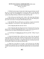
The LOGO! structure
LOGO! Basic (e.g.: 230 RC)
1
2
3
I7 I8
Q1 Q2 Q3 Q4
4
L1 N
4
90
LOGO! expansion module
(e.g.: DM8 230R)
4
Module slot with cap
5
6
RUN/STOP indicator
Control panel
(not for RCo)
LCD
(not for RCo)
I5 I6I2 I3 I4I1
Q4
Q1 Q2
L1 N I2 I3 I4I1
36
90
53
7
8
Mechanical coding
pins
3
1
2
9
9
10
9
Expansion interface
1
2
3
Outputs
Power supply
Inputs
8
88
10
Mechanical coding
sockets
10
11
11
Slide
1212
12 12
5
6
7
4
Q3
72
55
RUN/STOP
35
12121212
35
Ge
t
t
i
n
g
s
t
a
r
t
ed
w
i
t
h LOGO!
LOGO! Manual
A5E00380835-02
6
L
OGO! Basic (e.g.: 12
/
24 RC)
1
2
3
I7 I8
Q1 Q2 Q3 Q4
4
L+ M
4
6
5
90
L
OGO! e
x
pansion module
(e.g.: DM8 12/24R)
4
Module slot with cap
5
6
RUN/STOP indicator
Control panel
(not for RCo)
LCD
(not for RCo)
I5 I6I2 I3 I4I1
Q3 Q4
Q1 Q2
L+ M I2 I3 I4I1
90
7
8
Mechanical coding
pins
3
1
2
7
9
9
10
9
Expansion interface
1
2
3
Outputs
Power supply
Inputs
8
88
10
Mechanical coding
sockets
10
11
11
Slide
12121212
4
1212
1212
36
35
72
55
53
RUN/STOP
35
Ge
t
t
i
n
g
s
t
a
r
t
ed
w
i
t
h LOGO!
7
LOGO! Manual
A5E00380835-02
LOGO! expansion module
(e.g.: DM16 24R)
4
5
RUN/STOP indicator
Slide
35
72
90
53
6
Mechanical coding pins
3
1
2
7
7
8
7
Expansion interface
1
2
3
Outputs
Power supply
Inputs
66
8
Mechanical coding sockets
4
Q2
Q6
Q1 Q2
L+ M I2 I3 I4I1
Q5 Q8
Q3
I5 I6 I8I7
Q7
Q4
12
1212 1212
121212
4
5
RUN/STOP
RUN/STOP indicator
I1
PE
INPUT2x(0 10V/0 20mA)
L+ M
90
7
8
Mechanical coding
pins
1
7
9
9
10
9
Expansion interface
1
2
Power supply
Inputs
88
10
Mechanical coding
sockets
LOGO! AM 2
11
11
Slide
M1 U1 M2 U2I2
PE terminal, for con-
necting earth and the
shielding of analog
measuring cables.
12
12
4
L+ M
2
RUN/STOP
36 53
35
Ge
t
t
i
n
g
s
t
a
r
t
ed
w
i
t
h LOGO!
LOGO! Manual
A5E00380835-02
8
RUN/STOP indicator
V1+
PE
L+ M
90
7
8
Mechanical coding
pins
1
7
9
9
10
9
Expansion interface
1
2
Power supply
Outputs
88
10
Mechanical coding
sockets
11
11
Slide
PE terminal, for con-
necting earth
12
12
4
L+ M
2
M1 M2
V2+
1
LOGO! AM 2 AQ
OUTPUT 2x (0 10V)
RUN/STOP
35
53
36
RUN/STOP indicator,
communication with the
LOGO!
+
L+ M
90
7
8
Mechanical coding
pins
1
7
9
9
10
9
Expansion interface
1
2
Power supply
88
10
Mechanical coding
sockets
11
11
Slide
LED for status display
of EIB/KNX
12
12
4
2
1
L
OGO! CM EIB
/
K
N
X
Prog.
13
13
Programming button
EIB bus connection
RUN/STOP
BUS
35
36 53
Ge
t
t
i
n
g
s
t
a
r
t
ed
w
i
t
h LOGO!
9
LOGO! Manual
A5E00380835-02
How to identify LOGO!
The LOGO! identifier informs you of various properties:
S 12/24: 12/24 V D C version
S 230: 115 240 V AC version
S R: Relay outputs (without R: solid-state outputs)
S C: Integrated weekly timer
S o: Version without display (“LOGO! Pure”)
S DM: Digital module
S AM: Analog module
S CM: Communication module (e.g. EIB/KNX module)
Symbols
Version with display unit is equipped with 8 inputs and
4 outputs
Version without display unit is equipped with 8 inputs and
4 outputs
The digital module is equipped with 4 digital inputs and
4 digital outputs
The digital module is equipped with 8 digital inputs and
8 digital outputs
The analog module is equipped with 2 analog inputs
or two analog outputs, according to the device type
The communication module (CM); e.g. AS Interface is
equipped with 4 virtual inputs and 4 v irtual outputs
Ge
t
t
i
n
g
s
t
a
r
t
ed
w
i
t
h LOGO!
LOGO! Manual
A5E00380835-02
10
Versions
The following LOGO! versions are available:
Sym-
bol
Designation Supply
voltage
Inputs Outputs Properties
LOGO! 12/24 RC 12/24 V
DC
8 digital
(1)
4 relays
(10 A)
LOGO! 24 24 V DC 8 digital
(1)
4 solid
state
24V /
0.3A
no clock
LOGO! 24RC
(3)
24 V AC/
24 V DC
8 digital 4 relays
(10A)
LOGO! 230RC
(2)
115 240
V AC/DC
8 digital 4 relays
(10A)
LOGO! 12/24RCo 12/24 V
DC
8 digital
(1)
4 relays
(10A)
no display
unit
no keyboard
LOGO! 24o 24 V DC 8 digital
(1)
4 solid
state
24 V /
0.3A
no display
unit
no keyboard
no clock
LOGO! 24RCo
(3)
24 V AC /
24 V DC
8 digital 4 relays
(10A)
no display
unit
no keyboard
LOGO! 230RCo
(2)
115 240
V AC/DC
8 digital 4 relays
(10A)
no display
unit
no keyboard
(1): Of those can be used alternatively: 2 analog inputs (0 10V) and 2 fast
inputs.
(2): 230 V AC versions: Two groups consisting of 4 inputs each. Each input
within a group must be connected to the same phase. It is possible to intercon-
nect groups with a different phase.
(3): The digital inputs can be operated with P or N action.
Ge
t
t
i
n
g
s
t
a
r
t
ed
w
i
t
h LOGO!
11
LOGO! Manual
A5E00380835-02
Expansion modules
The following expansion modules can be connected to
LOGO!:
Symbol Name Power supply Inputs Outputs
LOGO! DM 8
12/24R
12/24 V DC 4 digital 4 relays (5A)
LOGO! DM 8 24 24 V DC 4 digital 4 solid state
24V / 0.3A
LOGO! DM 8 24R
(3)
24 V AC/DC 4 digital 4 relays (5A)
LOGO! DM 8
230R
115 240 V
AC/DC
4 digital
(1)
4 relays (5A)
LOGO! DM 16 24 24 V DC 8 digital 8 solid state
24V / 0.3A
LOGO! DM 16
24R
24 V DC 8 digital 8 relays (5A)
LOGO! DM 16
230R
115 240 V
AC/DC
8 digital
(4)
8 relays (5A)
LOGO! AM 2 12/24 V DC 2 analog
0 10V or 0
20mA
(2)
none
LOGO! AM 2
PT100
12/24 V DC 2 Pt100
5 0 ˚Cto
+200 ˚C
none
LOGO! AM 2 AQ 24 V DC none 2 analog
0 10 V DC
(1): Dif ferent phases are not allowed within the inputs.
(2): 0 10 V, 0 20 mA can be connected optionally.
(3): Digital inputs can be operated either with P or with N action.
(4): Two groups consisting of 4 inputs each. Each input within a group must be
connected to the same phase. It is possible to interconnect groups with a
different phase.
Ge
t
t
i
n
g
s
t
a
r
t
ed
w
i
t
h LOGO!
LOGO! Manual
A5E00380835-02
12
Communication modules
The following communication modules can be connected to
LOGO!:
Symbol Name Power
supply
Inputs Outputs
LOGO! CM AS In-
terface
30 V DC the next four in-
puts after the
physical inputs
of LOGO!
(I
n
I
n+3
)
the next four
outputs after the
physical outputs
of LOGO!
(Q
n
Q
n+3
)
LOGO! CM EIB/
KNX
24 V AC/
DC
max. 16 virtual
digital inputs (I)
;
max. 8 virtual
analog inputs
(AI)
max. 12 virtual
digital outputs
(Q)
;
max. 2 virtual
analog outputs
(AA)
Certification and approvals
LOGO! is certified to cULus and FM.
S cULus Haz. Loc.
Underwriters Laboratories Inc. (UL) to
UL 508 (Industrial Control Equipment)
CSA C22.2 N o. 142 (Process Control Equipment)
UL 1604 (Hazardous Location)
CSA-213 (Hazardous Location)
APPROVED for use in
Class I, Division 2, Group A, B, C, D Tx
Class I, Zone 2, Group IIC Tx
S FM Approval
Factory Mutual Research (FM) to
Approval Standard Class Number 3611, 3600, 3810
APPROVED for use in
Class I, Division 2, Group A, B, C, D Tx
Class I, Zone 2, Group IIC Tx
Ge
t
t
i
n
g
s
t
a
r
t
ed
w
i
t
h LOGO!
13
LOGO! Manual
A5E00380835-02
Note
You will find current approvals on the rating plate of the
relevant module.
!
Warning
Risk of personal injury and material damage.
In potentially explosive atmospheres, there is a risk of per-
sonal injury or damage to material if you disconnect con-
nectors when the system is in RUN.
In potentially explosive atmospheres, always switch off the
power supply to LOGO! and its components before you
disconnect any connectors.
LOGO! is issued with the C E Certificate of Conformity. It is
compliant with VDE 0631 and IEC 61131-2 and
interference-proof to EN 55011, Limit Class B.
Marine certification has been requested.
S ABS (American Bureau of Shipping)
S BV (Bureau Veritas)
S DNV (Det Norske Veritas)
S GL (Germanischer Lloyd)
S LRS (Lloyds Register of Shipping)
S Class NK (Nippon Kaiji Kyokai)
LOGO! is therefore suitable for use both in industry and in
the domestic area.
ID for A ustralia
Our products carrying the label shown at the side are com-
pliant with AS/NZS 2064:1997 (Class A) standard.
Recycling and Disposal
LOGO! units can be fully recycled, due to their low-pollutant
equipment. Contact a certified electronic waste disposal
center for environmentally acceptable recycling and dispos-
al of your old devices.
Ge
t
t
i
n
g
s
t
a
r
t
ed
w
i
t
h LOGO!
LOGO! Manual
A5E00380835-02
14
Ge
t
t
i
n
g
s
t
a
r
t
ed
w
i
t
h LOGO!
15
LOGO! Manual
A5E00380835-02
2 LOGO! installation and wiring
General guidelines
Please note the following guidelines for installing and wiring
your LOGO!:
S Always ensure that the wiring of y our LOGO! is com-
pliant with current rules and standards. Also, conform
with all national and regional regulations when you
install and operate the devices. For information on stan-
dards and regulations that apply to your specific case,
contact your local authorities.
S Always switch off power before you wire or install/re-
move a module.
S Always use cables with appropriate conductor cross-
sections for the relevant current. You can wire LOGO!
with cable conductor cross-sections from 1.5 mm
2
to 2.5
mm
2
; see Chapter 2.3.
S Do not exceed the screw torque of the terminals. The
maximum torque is: 0.5 N/m, see C hapter 2.3.
S Keep the cabling as short as possible. If longer cables
are necessary, y ou should use shielded versions. You
should always route your cables in pairs: i.e. one neutral
conductor plus one phase conductor or signal line.
S Always keep separate:
The AC wiring
High-voltage DC circuits with high-frequency switch-
ing cycles
Low-voltage signal wiring.
The EIB bus cable may also be laid in parallel to oth-
er signal lines.
S Ensure that the wires are installed with appropriate
strain relief.
S Provide a suitable lightning surge arrester for cables
installed in hazardous areas.