plc mitsubishi
Bạn đang xem bản rút gọn của tài liệu. Xem và tải ngay bản đầy đủ của tài liệu tại đây (1.55 MB, 215 trang )
-1-
Mitsubishi Melsec PLC
Ladder Logic Application
-2-
Content
I. The Structure and Understanding of PLC.
The Instruction and History of PLC.▷
Digital Input Module.▷
Digital Output Module.▷
Terminologies of Ladder Logic.▷
The Relationship between PLC Hardware and Software▷
Numeric System of PLC.▷
▷ Karnaugh Map
II. Application Examples for Logical Command.
Logical AND▷
Logical OR▷
Logical NAND▷
Logical NOR▷
Logical Exclusive OR▷
1 Scan-time Oscillator▷
Self-Holding, 0 or 1 Dominant SR/RS Flip-Flop▷
Detect Rising Edge / Falling Edge, Differentiation▷
Dual action Pushbutton▷
Trouble Acknowledge/ Reset▷
III. Application Example for Sequential Command.
On Delay / Off Delay Timer▷
One Shot Multi-vibrator▷
Multi-Vibrator▷
Speed Monitor using OFF Delay Timer▷
Preventing Chattering Noise for Mechanical Contacts▷
Finding Stable Value by TIME Filter from Analog Input Hunting▷
Measuring Time for Continuous Production.▷
Optimizing Surveillance Timer of Speed Monitor▷
Surveillance of Motor Drive System▷
Detecting Value Changed▷
-3-
IV. Application Example for Flow Sequential Command.
Sequence Control with BSFL Command▷
Sequence Control with SFTP Command▷
Call Subroutines and Return Processing▷
Sorting Data of Table in Maximum Order▷
V. Application Example for MUX-DEMUX.
Parallel Driving for▷ 7SegmentDisplay
Economic Discrete Input Multiplexing-Demultiplexing▷
VI. Application Example for Calculation Command.
Analog Input/Output Module▷
A1S68AD/ A1S68DAV,DAI Analog Input Module Set-up▷
Scaling for Analog Input PV▷
Schmitt Threshold ON-OFF▷
Peak Value Hold▷
On / Off Controller for Analog PV▷
Analog Value Clamping, Limitation▷
Bit Shift by Calculation Command▷
Analog Drive Speed Control▷
Finding Stable Value by SUM from Analog Input Hunting▷
Drive Multi-stage Control by Encoder Feedback▷
Ratio Control for Material Mixing▷
Trickle Control for Truck Loading▷
Rate Sampler for Single Counter▷
Analog Scaling for X 0 Shifted Signal▷
Analog Scaling for Y 0 Shifted Signal▷
Piecewise for Proportional Non-Linear Curve▷
Piecewise for Inverse Proportional Non-Linear Curve▷
Linear Profiler▷
-4-
VII. Application Example Data Manipulation Command.
Clearto0OrSetto1AllBits▷
Set All Bits to 1 by 2's Complement▷
Binary Counter▷
Assembling/ Disassembling of Bits▷
Acceleration/Deceleration Control With Linearity for Set-point▷
Individual ON/OFF Operation by Thumb-wheel Switch Set▷
Ring Counter▷
Display of Trouble Flag Number▷
Que Buffer and First-in/First-out▷
LIFO(Last In First Out) Using Stack Memory▷
Load/Save Data for 2-3 Dimensional Database▷
Data Save/ Sort/ Search for Optimization▷
VIII. Application Example for Computer Link Module.
Non-form Communication for Computer Link Module▷
CPU Direct Access via Computer Link Module▷
CPU Access via Dedicated MODEM and Computer Link Module▷
CPU Access via Dial-up MODEM and Computer Link Module▷
Proface GP577R Touch Screen Access via Computer Link▷
Module
Fix 32 Access via Computer Link Module▷
Intouch 5.6 Access via Computer Link Module▷
Appendix
MODICON Concept Version 2.1 PID Simulation Function Block Diagram▷
Bit Division for MMI Analog tag▷
SIMATIC TI545 PLC PID Simulation▷
SIMATIC TI545 PLC vs Intouch 8.0▷
Modicon E785 PLC vs Intouch 7.1 PID Simulation▷
-5-
I. The Structure and Understanding of PLC.
The Instruction and History of PLC.▷
Digital Input Module.▷
Digital Output Module.▷
Terminologies of Ladder Logic.▷
The Relationship between PLC Hardware and Software▷
Numeric System of PLC.▷
Karnaugh Map▷
-6-
Mitsubishi Melsec PLC Ladder Logic
Application
The Instruction and History of PLC.
1. Specfication and Unit of PLC.
- PLC is an abbireviation of "Programmable Logic Controller".
. The existing relay control box can be replaced to PLC.
. PLC performs logic solving and circulating beginning and end of program in the memory.
- The background of PLC is that,
. The end of 1960s, GM(General Motor) Company announced conditions of electronic
sequential control equipment proposed to apply to automotive assembly line, and
equipment manufacturer developed and distributed sequential control equipment suited
to these conditions.
- The function of these PLC is that
. Sequence control
. PID control, Analog control, Positioning control.
- Most of PLC has
. Basic operation function like AND, OR Contacts and Timer/Counter operation
. Practical Application operation like Subroutine, SHIFT, MASTER CONTROL, DATA
Calculation.
In the beginning, PLC could perform simple control by program as logic controller, high
performance function like arithmetic operation, output device control, communication
function were added. Also PLC could guarantee and complement high reliability that relay
control box couldn't have and flexibility to modify control system. By this way, time and costs
to needed to perform inspection, test-run could be minimize and save. After the time, the
development of integrated software for the communication between PLC and Computer could
make user program easily and provided more familiar environment and ability to build site
monitoring using graphic and graphic processing for the data as well as ability to analyze
difficult process problem with collected datum and information. Recently PLC are
manufactured more compact and lower cost and applied to almost industrial fields. When
users control the machine or equipment with PLC, users ought to make a program so that
PLC can decide memory content of control algorism. The standards Methods of PLC
Programming are presented but there are many differences according to Manufacturers and
kinds. IEC 1131-3
(International Electro-technical Commission- Standard for Programmable
Controllers-Part 3: Programming Languages) defined international standards of PLC
language as belows;
- LD(:Ladder diagram)
- IL(mnemonic :Instruction List)
- SFC(Sequential Function Charts)
-7-
- FBD(Function Block Diagram)
- ST(Structured Text).
PLC(Programmable Logic Controller) consists of Input & Output Interface, Memory,
Programming terminal, CPU, Power supply structurally.
2. The structure of PLC
A. CPU Unit
The CPU part of PLC is similar to structure of PC(Personal Computer) and the function are
also same. The main part of CPU is consisted as belows;
- Micro Processor( CPU) - System Memory - Program Memory - Data Memory.
(1) Program method.
In-build Program type stores all Sequence Program in the memory and call individually,
CPU analyzes and executes program.
(2) Control method.
- Constant cyclic repetition execution method solves and performs program stored memory
from first to end sequentially and return to first.
- Interrupt control method solves and performs interrupt execution program when the
internal or external interrupt demands.
(3) I/O control method
First, Processor reads input status from input module, and base on this data, solves logic
program from first to end. Finally processor writes results calculated from logic solving to
output module. This job processing is called "SCAN". The polling for I/O modules will be
indirect method and it should be executed before execution of Program 0 Step. This method
is represented as belows;
Input Polling
Output Processing
System Processing
LOGIC
SCAN
-8-
(4) Program Command
PLC command described in the specification is not for using CPU but for user command
designed by PLC manufacturer when user can make sequence program. Each command can
be different according to PLC manufacturer but it's not make so much different and function
is similar in every PLC's. Program command can be represented to two groups.
- Basic Command, Sequence Command : Basic Command is to perform sequence
diagram for relay circuits in the PLC, and consisted of basic logical operation
command like I/O Command for control signal, AND, OR.
- Applied Command : Applied Command provides various functions so that make
possible to perform transferring, calculation, comparison, data manipulation and
conversion, advanced sequential control program. By using applied command user
can save the programming and debugging time, use high speed, high performance
function.
B. Digital Input Unit
Digital input module of PLC is used to get the ON/OFF status from input device. This is
mainly used to get information from the machine. For each input device uses different power
consumption and different voltage when the pushbutton of operator panel and various kinds of
sensor is connected to input module, users should choose suitable input module to each input
devices.
Digital input module of PLC can be divided to DC input, AC input according to input voltage
type and isolated type or non-isolated type. The isolated type is meaning that there exists
photo-coupler at input part to isolate external and internal side and this is designed to endure
noise in the harsh industrial environment.
C. Digital Output Unit
Digital Output module of PLC outputs internal ON/OFF status of PLC and operates the
machine. Output devices can be connected are mainly lamps, magnet contactor, relays. After
magnet contactor(MC) and relay actuators are connected like motor or solenoid valve that can
operates the machine. For each output device uses different power consumption and different
voltage users should chooses the output module appropriate to output devices.
Digital Output module of PLC can be divided to relay output, transistor output, SSR(Solid
State Relay) unit according to output contact types.
D. Analog Signal
Analog value is meaning that physical quantity that varies continuously changing to time like
voltage, current, temperature, pressure, flow, velocity. Analog signal can not be connected to
computer or PLC that can connect only digital signal. So these physical quantities should
coverts to electrical signal like DC voltage, current and convert to digital amount again. Also
digital amount PLC inside should convert to analog signal to operate Servo-motor. DC/AC
speed control device that can be controlled by analog signal.
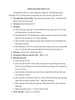
E. Analog Input Unit (A/D Converter)
This is for Analog/Digital conversion Unit and to use analog signal in the CPU. The principal
-9-
to convert from analog value to digital value is represented as the figure shows that digital
value corresponding to analog voltage signal as below. The input voltage range, output bits of
A/D converter are different according to kinds. The resolution of AD converter is determined
by output bits.
The resolution of AD converter is determined by formula as next.
Resolution ability = 2
N
(N = Output Bit Number)
Therefore, The resolution will be larger as larger as output bits and discriminal minimum
variation voltage can be expressed as next;
Analog voltage range(V) / 2
N
( N = Output Bit Number)
For example, when analog input between 0-5V is converted by 8 Bits output, analog input
voltage is 2V, we can find digital value,
Resolution= 2
8
= 256
If analog input voltage varies from 0V to 5V, output digital value will be varied from 0 to 255.
discriminal minimum variation voltage to change Digital value is;
V
IMIN
= 5 / 256 = 0.019531 , and
Digital value= 2V / 0.019531V = 102.4 = 102
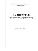
F. Analog Output Unit (D/A Converter)
This unit is for Digital/Analog conversion and used to output analog signal form CPU to
outside. The principal to convert from analog value to digital value is that output digital value
is corresponded to analog value. The resolution is proportional to the bit numbers to input(2
N
),
the output digital value will be converted to analog value from 0V to maximum reference
voltage.
Let's find analog value corresponding to digital value 102 if analog value is 0-5V voltage, the
resolution is 256, the voltage difference is 5V. Therefore the variation of digital 1 results
variation of analog signal 0.019531V(5/ 256). and we find 102 x 0.019531V 2 V calculation
result.
256
5V2V
102
0V
0
Analog DC Voltage
Digital Value
-10-
G. PID Control Unit
PID Control Unit has function of feed-back control so that system output make reference
voltage balance and maintain based on deviation between control variable and reference input,
recently this control type is mostly used in the industrial facilities.
(1) Proportional action - P Action
Controller Unit will control to decrease deviation between reference input and process
variable. At this time, when operation signal Z(t) is given, and if manipulated amount is
gotten, the relationship that manipulated quantities is proportional to operation signal Z(t)
is as belows;
y(t) = K Z(t)
We call this "Proportional action". And K, gain, will determine whether make
proportional action strong or weak.
If K, gain is high, the process variable will approach to reference signal rapidly, but
output can be fluctuated and this result make ill influence to total control stability. On the
contrary, if K, gain is low, the process variable will approach to reference signal slowly,
and there is possibility to that residual deviation occurs.
(2) Integral control action - I Action
Integral control action can be represented as action The variation velocity of manipulated
value given to control object is proportional to operation signal. Using this factor, we can
control integral control action. If integral time is longer, manipulated amount will be small
and the time to approach to reference signal is longer. On the contrary, if integral time is
shorter, manipulated amount will be large and the time to approach to reference signal is
shorter. The relationship of integral control action is as belows;
y(t) = K
∫ Z(t) dt
The integral control action is not used alone, by combination to P action or D action but can
be used to PI, PID action. The integral control action can eliminate residual deviation. If
integral time is to short, uncontrolled state can be occurred.
(3) Derivative action - D Action
Manipulated amount y(t) contributes to operation signal Z(t) by Derivative action.
Derivative action calculates manipulated value corresponding to deviation rate so that
suppress variation of deviation. The relation ship of derivative action is as follows;
y(t) = K dZ(t)/dt
Derivative action is not used alone, by combination to P action or D action but can be used
to PI, PID action. If derivative action is used to controller, process variable will approach to
reference signal rapidly and suppress the fast variation of process variable and external
disturbance.
(4) PID Control Unit
The relationship combined proportional, integral, derivative action described as above,
y(t) = K ( Z + 1/Ti
∫ Z(t) dt + Td dZ(t)/dt )
-11-
PID Unit is not used alone, but used together with analog input unit and analog output unit.
H. High speed Counter Unit
The counter in the CPU has nearly scan time below several ms for the CPU is scanning the
program. For this reason, CPU cannot count the pulse shorter than this scan time. Therefore
high speed counter unit operates separately with CPU, counts pulse as dedicated I/O unit. Also
high speed Counter Unit has comparing output function between set value and present value of
counter. It provides up and down counter and is used to detect position like the CNC machine.
I. Positioning Unit
The positioning Unit is used for precise motor control like Servo-Motor, Stepping Motor. This
unit will be applied to positioning decision of X-Y table, provides various operation patterns
like constant speed, acceleration, deceleration.
3. Data Link Methods.
It is commonly demanded the PLC has data exchanges between distributed remote I/O group,
different PLC system, high level computer. The data link unit can reduce or eliminate I/O points
and bulk cable installation, intends to build distributed control, data centralization and
management, monitoring system. The data link unit has function for data collecting of PLC,
extended I/O group.
Management Level
Cell Level
Field Level
-12-
Mitsubishi Melsec PLC Ladder Logic
Application
Digital Input Module
1. Types of Digital Input Module.
A. Digital Input Module of Sink Type .
For the digital Input Module of Sink Type, the current driving input point flows from pilot
signaler connected, like push-button switch, limit switch, proximity switch, to module inside,
the common point at the module will be N pole(N pole common). And if proximity switch is
connected, sensor Switch of PNP Open-Collector Type should be used. We calls this type
module Input Module of "Sink Type".
Sink Type
Digital Input
Module
A
P24
N24
B. Digital Input Module of Source Type.
For the source Type of Digital Input Module, the current already passes the wet point(for
example, photo-coupler) from power of P phase connected to module and flows to pilot
signaler connected to PLC input module, like push-button switch, limit switch, proximity
switch and the input point will be excited. the common point at the module will be P pole(P
pole common). And if proximity switch is connected, sensor Switch of NPN Open-Collector
Type should be used. We calls this type module input module of "Source Type".
-13-
Source Type
Digital Input
Module
A
N24
P24
C. In case of that proximity switch of PNP Open-Collector Type is connected to sink type
digital input module .
Sink Type
Digital Input
Module
A
N24
P24
N24
PNP Open-
Collector
Type 의
근접Switch
Proximity
Switch
of PNP
Open
Collector
Type
-14-
D. In case of that proximity switch of NPN Open-Collector Type is connected to source type
digital input module .
2. Digital AC Input Module.
For the Digital AC Input Module, additional rectifying circuit that from AC to DC and voltage
reducing circuit to fit to TTL or CMOS are exist in the input stage. The rest basic circuit is not so
much different with digital DC input module. Users should consider and select the sensor type
and common type of power in case of the digital DC input module.
P24
N24
NPN Open-
Collector
Type 의
근접Switch
Source Type
Digital Input
Module
A
P24
Proximity
Switch
of NPN
Open
Collector
Type
-15-
Mitsubishi Melsec PLC Ladder Logic
Application
Digital Output Module
1. Types of Digital Output Module.
A. Sink Type of Digital Output Module.
For the Sink Type of Digital Output Module, the current from power source of P pole flows
output device like Relay, Solenoid Coil that move Actuators and the load are driven by
semi-conductor switching device in the PLC, the common point of load is + terminal(P Pole
Common) and semi-conductor switching device will be NPN Type. We calls this type module
output module of "Sink Type".
Sink Type
Digital Output
Module
A
P24
N24
B. Source Type of Digital Output Module.
For the Source Type of Digital Output Module. the power source of P pole already connects to
PLC output module, the output device like Relay, Solenoid Coil that move Actuators is driven
by semi-conductor of PNP type. In case of this, the current drives output device comes out
from PLC inside to loads, the common of loads is N pole (N Pole Common). We calls this
type module output module of "Source Type".
-16-
Source Type
Digital Output
Module
A
P24
N24
C. Digital Relay Output Module.
For the Digital Relay Output Module, the relay contact(dry contact) driven by electronic
circuits and miniature relay drives output devices. therefore there exists not polarities and we
can use DC or AC power source within a electric capacity of internal relay.
Relay Type
Digital Output
Module
A
AC HOT
NEUT
-17-
D. Digital SSR Output Module.
Digital Relay Output Module can be used in the DC or AC, but Digital SSR Output Module
can not be used in the DC power source but can be used only AC power source.
SSR Type
Digital Output
Module
A
AC HOT
NEUT
This module includes TRIAC(a kind of semiconductor with large electric capacity) what we
call "SSR (Solid State Relay)", this semiconductor drives output device, once input signal
excites to signal gate, even gate signal is removed, turn-on state of SSR in the main driving
line will go on until main line current driving output device is ZERO. Therefore we cannot use
in the DC current that not to return to Zero current but can use in the AC current that crossing
zero voltage.
Gate 신호
-18-
Mitsubishi Melsec PLC Ladder Logic
Application
Terminologies of Ladder Logic
1. Terminologies of Ladder Logic.
A. Ladder Logic example
2. I/O Address and Instruction
A. Device I/O Address
Type of Device
Address
Description Remarks
X
External
Address
Input module address related to real hardware input
module
Bit
Address
Y
External
Address
Output module address related to real hardware
Output module
Bit
Address
M
Internal
Address
Internal Coil address used to contact and coil
internally
Bit
Address
L
Internal
Address
Internal Coil address used to contact and coil
internally. Even power supply go out, Status of bit is
maintained.(Retentive Coil)
Bit
Address
S
Internal
Address
Internal Coil address to perform sequential control
Bit
Address
B
Internal
Address
Communication Link relay when the data exchange
among the several PLC's
Bit
Address
F
Internal
Address
Internal Coil Address used as annunciator detecting
external faults.
Bit
Address
D
Internal &
External
Address
Word address for calculating, manipulation, storing
data, for using internally and externally
Word
Address
and
and
-19-
Device I/O Address can be divided to internal address and external address. The external is
allocated and related to real hardware I/O module, the internal address is used only in the
program logic.
B. Identification of Device I/O Address.
Device I/O Address consists of Identifier and decimal number or hexadecimal number. For
example,
X000, Y1F, M058, D103, N001
C. Allocation of Device I/O Address.
Allocation of Device I/O address to PLC Hardware can be performed as follows;
- Assigned X OR Y address sequentially.
- Started from first slot excluded CPU module.
- assigned memory address size that I/O modules needed.
UC24
DI 32pt
DO 32pt
DO 16pt
DI 16pt
NULL
X060-Y07F
Y040-Y05F
Y030-Y03F
X010-X02F
X000-X00F
POWE
R
3. Symbolization of Ladder Logic.
A. Power Rail Left
The Left side of ladder logic is starting point of power energy. This regards as start of control
power line of sequence circuit. Power flow can proceed from left side of ladder logic to right
side of ladder logic, from here, ladder logic(Instruction) like logical contact, sequential
command, data manipulation, calculation command can be built.
B. Power Flow
From Power Rail Left, each command and instruction can be built and this will make input
condition and decision making and execution. According to input condition, power flow will
pass to the right side along the possible routes. When reaching to output command, execution
will be perform. So command related to execution will be located in the right side.
C. Power Rail Right
This regards as end line of control power supply in the sequence and power flow will be ended
at this point.
-20-
D. Rung
Rung can be represented to grouping of input condition and output task. If this group is
continuous, not separated, this group can be called " Rung".
E. Step
The step is represented to Word Number consisting of Instruction, and we can calculate total
program memory size.
-21-
Mitsubishi Melsec PLC Ladder Logic
Application
Relation between PLC Hardware and Software
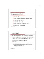
1. In case of Digital Input Module.
The how act external electrical excitation to PLC inside ladder logic is represented as next. To
speak exactly, When we press the push-button switch connected to PLC input module, let'
consider what is happened to the PLC internal logic corresponding to the push-button switch
contact.
The figure as next is represented before pressing the push-button switch has A contact.
The current from power P pole cannot flow to PLC input module address X000 because of
opening of pushbutton switch(NO: Normal Open state) in the electrical circuit. This is to say, at
the input point addressed to X000 of input module, there exists not external electrical excitation,
we can say this "Electrically Dry State". Otherwise, in the PLC inside, NO(Normal Opened)
contact of un-identified X000(not excited because of opening of pushbutton switch) can not
make power flow proceed, so this NO contact is electrically OFF state. But in the PLC inside,
NC(Normal Closed) contact of un-identified X000 can proceed power flow, so this contact is
electrically ON state.
X000
P24
N24
X000
X000
PLC 내부 Logic
PLC 외부 회로
Y010
Power Flow
Power
Rail
Left
Power
Rail
Right
Instruction
PLC External Circuit
PLC Internal Logic
-22-
Now by pressing the A contact of Push-Button Switch, there exists electrical excitation at the
X000 and we can say this "Electrically Wet State". In the PLC Logic, NO(Normal Opened)
contact of identified X000(excited because of closing of pushbutton switch) can proceed power
flow and change to closed state, so this NO contact is electrically ON state. But in the PLC
inside, NC(Normal Closed) contact of identified X000 can not make power flow proceed and
changed to opened state, so this contact is electrically OFF state.
Totally, we can say them as follows;
Electrical State
corresponding to PLC
INPUT point
Lamp Status
corresponding to PLC
INPUT point
Contact state in the
PLC Internal Logic
Possibility to pass
the Power Flow
Electrically Dry State
OFF NO(Normal Open) No
OFF NC(Normal Close) Yes
Electrically Wet State
ON NO(Normal Open) Yes
ON NC(Normal Close) No
X000
P24
N24
X000
X000
PLC 내부 Logic
PLC 외부 회로
Y010
Power Flow
Power
Rail
Left
Power
Rail
Right
Instruction
PLC External Circuit
PLC Internal Logic
-23-
2. In case of Digital Output Module.
The how act internal ladder logic variation to PLC outside hardware is represented as next in
case of Digital Output Module.
If Y010 Coil Instruction in the PLC internal Logic is Energized, the Relay 010 connected to
addressed Y010 of Digital Output Module is also Energized. Otherwise if Y011 Coil Instruction
in the PLC internal Logic is De-energized, the Relay 011 connected to addressed Y011 of Digital
Output Module is also De-energized.
Source Type
Digital Output
Module
P24
N24
X000
X000
PLC 내부 Logic
Y010
Power
Rail
Left
Power
Rail
Right
Instruction
Y010
Relay 010
Y011
Y011
Relay 011
PLC External Circuit
PLC Internal Logic
-24-
Mitsubishi Melsec PLC Ladder Logic
Application
Numeric System of PLC.
1. Numeric System and DATA
The numeric system based on 10(Decimal) is developed naturally and used generally but
considering logic system of ON and OFF state, this will be numeric system based on
2(Binary numeric system). In the computer system, binary numeric system based on 2
is generally used, and also 4,8,16 or 32 numeric system is used.
Numbering Systems
Numbers in Decimal, Binary, Octal and Hexadecimal
In the each numeric system, even it's basic numeric system is different, existing real
value will not be changed. Now from here, let's consider for numeric system and
conversion between the different systems needed to understanding the instruction used
in the PLC(Programmable Logic Controller).
Base Name Data Unit
2 Binary Bit
8 Octal Nibble
10 Decimal Digit
16 Hexadecimal Byte
Decimal Binary Octal Hexadecimal
0 0 0 0
1 1 1 1
2 10 2 2
3 11 3 3
4 100 4 4
5 101 5 5
6 110 6 6
7 111 7 7
8 1000 10 8
9 1001 11 9
10 1010 12 A
11 1011 13 B
12 1100 14 C
13 1101 15 D
14 1110 16 E
15 1111 17 F
16 10000 20 10
17 10001 21 11
18 10010 22 12
19 10011 23 13
20 10100 24 14
-25-
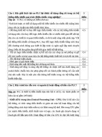
2. Numeric System
A. Binary Numeric System
Binary number is commonly used in the computer. 1 digit of binary number will be
regarded as the state of 1 electric wire, if the voltage on the wire is ON state, it's bit
value is 1, if the voltage on the wire is OFF state, it's bit value is 0. If two wires
are used, bits will be generated asa well as wires number used. The following figure
is represented that 10 decimal number equivalent to each binary numbers, minimum
number is positioned from right side. Minimum number is 1, and position number is
0. The way to find from binary number to decimal number is changing the position
number to exponent number of 2 and converting to decimal number, adding all each
values. As this way, the conversion from other numeric system to decimal number is
possible.
2
6
=64 2
5
=32 2
4
=16 2
3
=8 2
2
=4 2
1
=2 2
0
=1
1110001
1(2
6
)= 64
1(2
5
)= 32
1(2
4
)= 16
1(2
3
)= 8
1(2
2
)= 4
1(2
1
)= 2
1(2
0
)= 1
113
Conversion of a Binary Number to a Decimal Number
In every numeric system, the
LSD(Least significant digit) is
located at most right side, the
MSD(Least significant digit) is
locatedatmostleftside.