lap trinh HDL
Bạn đang xem bản rút gọn của tài liệu. Xem và tải ngay bản đầy đủ của tài liệu tại đây (2.2 MB, 461 trang )
Design Through Verilog HDL
padmanabham-fm.qxd 8/18/2003 8:43 AM Page i
IEEE Press
445 Hoes Lane
Piscataway, NJ 08854
IEEE Press Editorial Board
Stamatios V. Kartalopoulos, Editor in Chief
M. Akay M. E. El-Hawary M. Padgett
J. B. Anderson R. J. Herrick W. D. Reeve
R. J. Baker D. Kirk S. Tewksbury
J. E. Brewer R. Leonardi G. Zobrist
M. S. Newman
Kenneth Moore, Director of IEEE Press
Catherine Faduska, Senior Acquisitions Editor
Christina Kuhnen, Associate Acquisitions Editor
Technical Reviewers
Robert S. Hanmer, Lucent Technologies, Naperville, IL
Zhou Feng, Fudan University, China
padmanabham-fm.qxd 8/18/2003 8:43 AM Page ii
Design Through Verilog HDL
T. R. Padmanabhan
B. Bala Tripura Sundari
A JOHN WILEY & SONS, INC., PUBLICATION
IEEE PRESS
padmanabham-fm.qxd 8/18/2003 8:43 AM Page iii
Copyright © 2004 by the Institute of Electrical and Electronics Engineers, Inc. All rights reserved.
Published simultaneously in Canada.
No part of this publication may be reproduced, stored in a retrieval system or transmitted in any form or
by any means, electronic, mechanical, photocopying, recording, scanning or otherwise, except as
permitted under Section 107 or 108 of the 1976 United States Copyright Act, without either the prior
written permission of the Publisher, or authorization through payment of the appropriate per-copy fee to
the Copyright Clearance Center, Inc., 222 Rosewood Drive, Danvers, MA 01923, (978) 750-8400, fax
(978) 750-4744, or on the web at www.copyright.com. Requests to the Publisher for permission should
be addressed to the Permissions Department, John Wiley & Sons, Inc., 111 River Street, Hoboken, NJ
07030, (201) 748-6011, fax (201) 748-6008, e-mail:
Limit of Liability/Disclaimer of Warranty: While the publisher and author have used their best efforts in
preparing this book, they make no representation or warranties with respect to the accuracy or
completeness of the contents of this book and specifically disclaim any implied warranties of
merchantability or fitness for a particular purpose. No warranty may be created or extended by sales
representatives or written sales materials. The advice and strategies contained herein may not be
suitable for your situation. You should consult with a professional where appropriate. Neither the
publisher nor author shall be liable for any loss of profit or any other commercial damages, including
but not limited to special, incidental, consequential, or other damages.
For general information on our other products and services please contact our Customer Care
Department within the U.S. at 877-762-2974, outside the U.S. at 317-572-3993 or fax 317-572-4002.
Wiley also publishes its books in a variety of electronic formats. Some content that appears in print,
however, may not be available in electronic format.
Library of Congress Cataloging-in-Publication Data:
Padmanabhan, T. R.
Design through Verilog HDL / T. R. Padmanabhan, B. Bala Tripura Sundari.
p. cm.
Includes bibliographical references and index.
ISBN 0-471-44148-1 (cloth)
1. Verilog (Computer hardware description language) I. Tripura Sundari, B. Bala. II.
Title.
TK7885.7.P37 2003
621.39'2–dc22 2003057671
Printed in the United States of America.
10987654321
padmanabham-fm.qxd 8/18/2003 8:43 AM Page iv
v
To my parents
B. Bala Tripura Sundari
To Ravi and Chandra
T.R. Padmanabhan
vii
CONTENTS
PREFACE xi
ACKNOWLEDGEMENTS xiii
1 INTRODUCTION TO VLSI DESIGN 1
1.1 INTRODUCTION 1
1.2 CONVENTIONAL APPROACH TO DIGITAL DESIGN 1
1.3 VLSI DESIGN 3
1.4 ASIC DESIGN FLOW 4
1.5 ROLE OF HDL 9
2 INTRODUCTION TO VERILOG 11
2.1 VERILOG AS AN HDL 11
2.2 LEVELS OF DESIGN DESCRIPTION 11
2.3 CONCURRENCY 13
2.4 SIMULATION AND SYNTHESIS 14
2.5 FUNCTIONAL VERIFICATION 14
2.6 SYSTEM TASKS 16
2.7 PROGRAMMING LANGUAGE INTERFACE (PLI) 16
2.8 MODULE 16
2.9 SIMULATION AND SYNTHESIS TOOLS 22
2.10 TEST BENCHES 27
3 LANGUAGE CONSTRUCTS AND CONVENTIONS IN VERILOG 31
3.1 INTRODUCTION 31
3.2 KEYWORDS 31
3.3 IDENTIFIERS 32
3.4 WHITE SPACE CHARACTERS 33
3.5 COMMENTS 33
3.6 NUMBERS 34
3.7 STRINGS 36
3.8 LOGIC VALUES 38
3.9 STRENGTHS 39
3.10 DATA TYPES 40
3.11 SCALARS AND VECTORS 41
3.12 PARAMETERS 42
viii CONTENTS
3.13 MEMORY 43
3.14 OPERATORS 43
3.15 SYSTEM TASKS 44
3.16 EXERCISES 46
4 GATE LEVEL MODELING – 1 47
4.1 INTRODUCTION 47
4.2 AND GATE PRIMITIVE 47
4.3 MODULE STRUCTURE 50
4.4 OTHER GATE PRIMITIVES 51
4.5 ILLUSTRATIVE EXAMPLES 51
4.6 TRI-STATE GATES 64
4.7 ARRAY OF INSTANCES OF PRIMITIVES 66
4.8 ADDITIONAL EXAMPLES 69
4.9 EXERCISES 79
5 GATE LEVEL MODELING – 2 81
5.1 INTRODUCTION 81
5.2 DESIGN OF FLIP-FLOPS WITH GATE PRIMITIVES 81
5.3 DELAYS 91
5.4 STRENGTHS AND CONTENTION RESOLUTION 102
5.5 NET TYPES 109
5.6 DESIGN OF BASIC CIRCUITS 115
5.7 EXERCISES 124
6 MODELING AT DATA FLOW LEVEL 127
6.1 INTRODUCTION 127
6.2 CONTINUOUS ASSIGNMENT STRUCTURES 127
6.3 DELAYS AND CONTINUOUS ASSIGNMENTS 133
6.4 ASSIGNMENT TO VECTORS 135
6.5 OPERATORS 136
6.6 ADDITIONAL EXAMPLES 150
6.7 EXERCISES 157
7 BEHAVIORAL MODELING — 1 159
7.1 INTRODUCTION 159
7.2 OPERATIONS AND ASSIGNMENTS 160
7.3 FUNCTIONAL BIFURCATION 161
7.4 INITIAL CONSTRUCT 164
7.5 ALWAYS CONSTRUCT 168
7.6 EXAMPLES 170
7.7 ASSIGNMENTS WITH DELAYS 184
7.8 wait CONSTRUCT 192
7.9 MULTIPLE ALWAYS BLOCKS 195
CONTENTS ix
7.10 DESIGNS AT BEHAVIORAL LEVEL 197
7.11 BLOCKING AND NONBLOCKING ASSIGNMENTS 201
7.12 THE case STATEMENT 205
7.13 SIMULATION FLOW 214
7.14 EXERCISES 217
8 BEHAVIORAL MODELING II 219
8.1 INTRODUCTION 219
8.2 if AND if–else CONSTRUCTS 219
8.3 assign–deassign CONSTRUCT 225
8.4 repeat CONSTRUCT 236
8.5 for LOOP 238
8.6 THE disable CONSTRUCT 244
8.7 while LOOP 249
8.8 forever LOOP 254
8.9 PARALLEL BLOCKS 258
8.10 force–release CONSTRUCT 261
8.11 EVENT 266
8.12 EXERCISES 268
9 FUNCTIONS, TASKS, AND USER-DEFINED PRIMITIVES 273
9.1 INTRODUCTIUON 273
9.2 FUNCTION 273
9.3 TASKS 286
9.4 USER-DEFINED PRIMITIVES (UDP) 292
9.5 EXERCISES 302
10 SWITCH LEVEL MODELING 305
10.1 INTRODUCTION 305
10.2 BASIC TRANSISTOR SWITCHES 305
10.3 CMOS SWITCH 318
10.4 BIDIRECTIONAL GATES 328
10.5 TIME DELAYS WITH SWITCH PRIMITIVES 333
10.6 INSTANTIATIONS WITH STRENGTHS AND DELAYS 334
10.7 STRENGTH CONTENTION WITH TRIREG NETS 334
10.8 EXERCISES 337
11 SYSTEM TASKS, FUNCTIONS, AND COMPILER DIRECTIVES 339
11.1 INTRODUCTION 339
11.2 PARAMETERS 339
11.3 PATH DELAYS 348
11.4 MODULE PARAMETERS 371
11.5 SYSTEM TASKS AND FUNCTIONS 373
11.6 FILE-BASED TASKS AND FUNCTIONS 383
x CONTENTS
11.7 COMPILER DIRECTIVES 385
11.8 HIERARCHICAL ACCESS 393
11.9 GENERAL OBSERVATIONS 404
11.10 EXERCISES 405
12 QUEUES, PLAS, AND FSMS 407
12.1 INTRODUCTION 407
12.2 QUEUES 407
12.3 PROGRAMMABLE LOGIC DEVICES (PLDs) 414
12.4 DESIGN OF FINITE STATE MACHINES 418
12.5 EXERCISES 433
APPENDIX A (Keywords and Their Significance) 443
APPENDIX B (Truth Tables of Gates and Switches) 447
REFERENCES 449
INDEX 451
xi
PREFACE
Verilog has rapidly become a widely accepted language for VLSI design. The
language is well-structured and defined to cater to the steady increase in the size of
ICs to be designed without sacrificing the advantages associated with design at the
“grass roots” level. A designer aspiring to master the language in its versatility
should become familiar with the various constructs in it, practice their use in real
applications, and use them in combinations to be successful.
Describing a design using Verilog is only half the story: Writing Test
benches, testing a design for all its desired functions, and identifying the faults and
removing them remain equally challenging tasks. This book is an attempt to
address these issues effectively. The constructs in Verilog are discussed through
apt illustrative examples. Equal importance is given to design description and test
benches. The examples have been tested with popular and commonly used
simulation packages and the results reproduced. In many of the cases the tested
designs have been synthesized, and the synthesized circuit has also been
reproduced. “Seeing is believing”: Seeing a design available as a software routine,
transformed to a circuit, will add a lot to the confidence level of novices who use
the book. flip-flops, counters, registers, coders, decoders, mux, demux etc., have
been considered at different levels of design; this should help in clarifying the
perspectives regarding levels, need, and significance.
Place and significance of Verilog in VLSI design have been brought out in
Chapters 1 and 2. Basics of the language, its conventions, etc., are dealt with in
Chapters 2 and 3. Chapters 4 and 5 form an introduction to design through
Verilog. It is done at the gate level, which may be the most comfortable for the
beginner. Any design, however involved it may be, can be completely realized in
terms of the gate primitives of Verilog. We hope that the illustrative examples
considered and the exercises at the end of the chapters, impart such a confidence to
a designer. Chapter 6 is devoted to design at the data flow level. Continuous
assignments using operators linking operands, which allow designs to be described
more compactly but still close enough to the circuit level, form the theme of this
chapter. Behavioral level design is discussed in Chapters 7 and 8. Mastery at this
level – akin to the C language – is essential for a successful designer working at
the system level. Functions and tasks, which facilitate structuring of designs and
their orderly description, form the theme of Chapter 9. The switch primitives in
Verilog constitute the link with actual VLSI implementation although their
mastery is not essential to many of the designers with their higher level activities.
Chapter 10 is devoted exclusively to switch level design; since it stands out from
xii PREFACE
the main text flow so far, its discussion is consciously deferred to this stage.
Chapter 11 forms an introduction to the system tasks and functions in Verilog and
their use in typical environments. Chapter 12 deals with design using PLDs and
FSMs. Though subdued, the treatment is enough to give the necessary lead to
more comprehensive designs.
All the chapters have enough exercises at the end. Some help mastery of the
material in the chapter, through practice; others are structured to stimulate the
users to explore avenues of their own. The step-by-step build-up of a processor in
Chapter 12 is of this type.
All simulation results presented in the text as part of illustrative examples,
have been obtained using the “Modelsim” software of Mentor Graphics. All
synthesis results wherever presented, have been obtained using the “Leonardo
Spectrum” software of Mentor Graphics. These have been reproduced by courtesy
of Mentor Graphics.
Users’ views and suggestions are welcome; for this purpose, the website
www.aitec.amrita.edu/publications may be accessed.
T. R. P
ADMANABHAN
B. BALA TRIPURA SUNDARI
July 2003
ACKNOWLEDGEMENTS
Many of our acquaintances and associates have contributed to the fruition of this
venture. K.N.C. Eswaran is responsible for all the delicate and subtle touches with
Word. Our colleagues — Subha, Sathyapriya, and Rajagopal — have made many
useful suggestions. Anand Srinivasan helped with simulation in his own way.
Ajai Narendran of the Systems Wing of our Institute has been helpful in many
ways. Our families — Krishna Sudarshan, Saketh, Srikanth, Ravi, Chandra, and
Uma — have put up with our transient oddities. Brahmachari Abhayamrita
Chaitanya — Chief Operating Officer of Amrita Vishwa Vidyapeetham — made
the Institute facilities, especially the VLSI laboratory, available for us.
Dr. N. Narayana Pillai, Dean (Students), and Prof. R. Sundararajan of our Institute
have been of great encouragement to us. Ms Christina Kuhnen, Associate
Acquisitions Editor at IEEE Press, has been quite helpful throughout; she has
effectively bridged the distance between New York and Coimbatore. The
painstaking efforts of the Referees to wade through the manuscript, understand the
matter and their constructive suggestions have conspicuously contributed to the
book in its present form. We give our sincere thanks to all of them.
Our obeisance goes to Mata Amritanandamayi Devi for her commitment to
societal transformation through quality education; this is a humble attempt to add
another brick to the edifice being built by her.
1
1
INTRODUCTION TO VLSI DESIGN
1.1 INTRODUCTION
The word digital has made a dramatic impact on our society. More significant is a
continuous trend towards digital solutions in all areas – from electronic
instrumentation, control, data manipulation, signals processing, telecom-
munications etc., to consumer electronics. Development of such solutions has been
possible due to good digital system design and modeling techniques.
1.2 CONVENTIONAL APPROACH TO DIGITAL DESIGN
Digital ICs of SSI and MSI types have become universally standardized and have
beenaccepted for use. Whenever a designer has to realize a digital function, he
uses a standard set of ICs along with a minimal set of additional discrete circuitry.
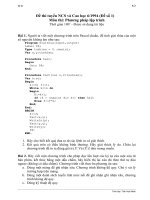
Consider a simple example of realizing a function as
Q
n+1
= Q
n
+ (A B)
Here Q
n,
A, and B are Boolean variables, with Q
n
being the value of Q at the nth
time step. Here A B signifies the logical AND of A and B; the ‘+’ symbol signifies
the logical OR of the logic variables on either side. A circuit to realize the
function is shown in Figure 1.1. The circuit can be realized in terms of two ICs –
an A-O-I gate and a flip-flop. It can be directly wired up, tested, and used.
A
clk
Q
n
B
Figure 1.1 A simple digital circuit.
Design Through Verilog HDL. T. R. Padmanabhan and B. Bala Tripura Sundari
Copyright
2004 Institute of Electrical and Electronics Engineers, Inc.
ISBN: 0-471-44148-1
2 INTRODUCTION TO VLSI DESIGN
With comparatively larger circuits, the task mostly reduces to one of
identifying the set of ICs necessary for the job and interconnecting; rarely does one
have to resort to a microlevel design [Wakerly]. The accepted approach to digital
design here is a mix of the top-down and bottom-up approaches as follows [Hill &
Peterson]:
x Decide the requirements at the system level and translate them to circuit
requirements.
x Identify the major functional blocks required like timer, DMA unit, register-
file etc., say as in the design of a processor.
x Whenever a function can be realized using a standard IC, use the same –for
example programmable counter, mux, demux, etc.
x Whenever the above is not possible, form the circuit to carry out the block
functions using standard SSI – for example gates, flip-flops, etc.
x Use additional components like transistor, diode, resistor, capacitor, etc.,
wherever essential.
Once the above steps are gone through, a paper design is ready. Starting with
the paper design, one has to do a circuit layout. The physical location of all the
components is tentatively decided; they are interconnected and the ‘circuit-on-
paper’ is made ready. Once a paper design is done, a layout is carried out and a
net-list prepared. Based on this, the PCB is fabricated, and populated and all the
populated cards tested and debugged. The procedure is shown as a process
flowchart in Figure 1.2.
System requirements
ICs
Circuit requirements
Other components
PCB layout
Wiring & testing
Final circuit
Figure 1.2 Sequence of steps in conventional electronic circuit design.
VLSI DESIGN 3
At the debugging stage one may encounter three types of problems:
x Functional mismatch: The realized and expected functions are different. One
may have to go through the relevant functional block carefully and locate any
error logically. Finally the necessary correction has to be carried out in
hardware.
x Timing mismatch: The problem can manifest in different forms. One
possibility is due to the signal going through different propagation delays in
two paths and arriving at a point with a timing mismatch. This can cause
faulty operation. Another possibility is a race condition in a circuit involving
asynchronous feedback. This kind of problem may call for elaborate
debugging. The preferred practice is to do debugging at smaller module
stages and ensuring that feedback through larger loops is avoided: It becomes
essential to check for the existence of long asynchronous loops.
x Overload: Some signals may be overloaded to such an extent that the signal
transition may be unduly delayed or even suppressed. The problem manifests
as reflections and erratic behavior in some cases (The signal has to be suitably
buffered here.). In fact, overload on a signal can lead to timing mismatches.
The above have to be carried out after completion of the prototype PCB
manufacturing; it involves cost, time, and also a redesigning process to develop a
bugfree design.
1.3 VLSI DESIGN
The complexity of VLSIs being designed and used today makes the manual
approach to design impractical. Design automation is the order of the day. With
the rapid technological developments in the last two decades, the status of VLSI
technology is characterized by the following [Wai-kai, Gopalan]:
x A steady increase in the size and hence the functionality of the ICs.
x A steady reduction in feature size and hence increase in the speed of operation
as well as gate or transistor density.
x A steady improvement in the predictability of circuit behavior.
x A steady increase in the variety and size of software tools for VLSI design.
The above developments have resulted in a proliferation of approaches to VLSI
design. We briefly describe the procedure of automated design flow [Rabaey,
Smith MJ]. The aim is more to bring out the role of a Hardware Description
Language (HDL) in the design process. An abstraction based model is the basis of
the automated design.
4 INTRODUCTION TO VLSI DESIGN
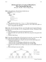
1.3.1 Abstraction Model
The model divides the whole design cycle into various domains (see Figure 1.3).
With such an abstraction through a division process the design is carried out in
different layers. The designer at one layer can function without bothering about
the layers above or below. The thick horizontal lines separating the layers in the
figure signify the compartmentalization. As an example, let us consider design at
the gate level. The circuit to be designed would be described in terms of truth
tables and state tables. With these as available inputs, he has to express them as
Boolean logic equations and realize them in terms of gates and flip-flops. In turn,
these form the inputs to the layer immediately below. Compartmentalization of
the approach to design in the manner described here is the essence of abstraction;
it is the basis for development and use of CAD tools in VLSI design at various
levels.
The design methods at different levels use the respective aids such as
Boolean equations, truth tables, state transition table, etc. But the aids play only a
small role in the process. To complete a design, one may have to switch from one
tool to another, raising the issues of tool compatibility and learning new
environments.
1.4 ASIC DESIGN FLOW
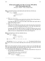
As with any other technical activity, development of an ASIC starts with an idea
and takes tangible shape through the stages of development as shown in Figure 1.4
and shown in detail in Figure 1.5. The first step in the process is to expand the
idea in terms of behavior of the target circuit. Through stages of programming, the
same is fully developed into a design description – in terms of well defined
standard constructs and conventions.
Behavioral domain
System (
Performance
specifications
)
Chip (
Micro-operations
)
Register
(
Truth tables, state tables
)
Gate (
Boolean equations
)
Circuit (differential equations)
Silicon (
none
)
Structural domain
Processing core : nondigital,
nonelectronic systems
Microprocessors,
memories, I/O devices
Registers, ALU,
multipliers
Gates, flip-flops
Transistors, L, R, C
Geometric objects
Figure 1.3 Design domain and levels of abstraction.
ASIC DESIGN FLOW 5
Idea
SynthesisSimulation
Design description
Physical
design
Figure 1.4 Major activities in ASIC design.
The design is tested through a simulation process; it is to check, verify, and
ensure that what is wanted is what is described. Simulation is carried out through
dedicated tools. With every simulation run, the simulation results are studied to
identify errors in the design description. The errors are corrected and another
simulation run carried out. Simulation and changes to design description together
form a cyclic iterative process, repeated until an error-free design is evolved.
Design description is an activity independent of the target technology or
manufacturer. It results in a description of the digital circuit. To translate it into a
tangible circuit, one goes through the physical design process. The same
constitutes a set of activities closely linked to the manufacturer and the target
technology
1.4.1 Design Description
The design is carried out in stages. The process of transforming the idea into a
detailed circuit description in terms of the elementary circuit components
constitutes design description. The final circuit of such an IC can have up to a
billion such components; it is arrived at in a step-by-step manner.
The first step in evolving the design description is to describe the circuit in
terms of its behavior. The description looks like a program in a high level
language like C. Once the behavioral level design description is ready, it is tested
extensively with the help of a simulation tool; it checks and confirms that all the
expected functions are carried out satisfactorily. If necessary, this behavioral level
routine is edited, modified, and rerun – all done manually. Finally, one has a
design for the expected system – described at the behavioral level. The behavioral
design forms the input to the synthesis tools, for circuit synthesis. The behavioral
constructs not supported by the synthesis tools are replaced by data flow and gate
level constructs. To surmise, the designer has to develop synthesizable codes for
his design.
6 INTRODUCTION TO VLSI DESIGN
Data flow level
description
Gate level
description
Switch level
description
Compile / edit Simulate
Compile / edit Simulate
Compile / edit Simulate
Compile / edit Simulate
Optimization
Prototype
Synthesis
FPGA based
design
Final circuit
System partitioning
Floor planning
Placement
Routing
Mask
Verification
Feature extraction
Physical design
Idea
Behavioral level
description
Logical design
(Scope of HDL)
Scope of
simulation tool
Figure 1.5ASIC design and development flow.
The design at the behavioral level is to be elaborated in terms of known and
acknowledged functional blocks. It forms the next detailed level of design
description. Once again the design is to be tested through simulation and
iteratively corrected for errors. The elaboration can be continued one or two steps
further. It leads to a detailed design description in terms of logic gates and
transistor switches.
ASIC DESIGN FLOW 7
1.4.2 Optimization
The circuit at the gate level – in terms of the gates and flip-flops – can be
redundant in nature. The same can be minimized with the help of minimization
tools. The step is not shown separately in the figure. The minimized logical
design is converted to a circuit in terms of the switch level cells from standard
libraries provided by the foundries. The cell based design generated by the tool is
the last step in the logical design process; it forms the input to the first level of
physical design [Micheli].
1.4.3 Simulation
The design descriptions are tested for their functionality at every level –
behavioral, data flow, and gate. One has to check here whether all the functions
are carried out as expected and rectify them. All such activities are carried out by
the simulation tool. The tool also has an editor to carry out any corrections to the
source code. Simulation involves testing the design for all its functions, functional
sequences, timing constraints, and specifications. Normally testing and
simulation at all the levels – behavioral to switch level – are carried out by a single
tool; the same is identified as “scope of simulation tool” in Figure 1.5.
1.4.4 Synthesis
With the availability of design at the gate (switch) level, the logical design is
complete. The corresponding circuit hardware realization is carried out by a
synthesis tool. Two common approaches are as follows:
x The circuit is realized through an FPGA [Oldfield]. The gate level design
description is the starting point for the synthesis here. The FPGA vendors
provide an interface to the synthesis tool. Through the interface the gate level
design is realized as a final circuit. With many synthesis tools, one can
directly use the design description at the data flow level itself to realize the
final circuit through an FPGA. The FPGA route is attractive for limited
volume production or a fast development cycle.
x The circuit is realized as an ASIC. A typical ASIC vendor will have his own
library of basic components like elementary gates and flip-flops. Eventually
the circuit is to be realized by selecting such components and interconnecting
them conforming to the required design. This constitutes the physical design.
Being an elaborate and costly process, a physical design may call for an
intermediate functional verification through the FPGA route. The circuit
realized through the FPGA is tested as a prototype. It provides another
opportunity for testing the design closer to the final circuit.
8 INTRODUCTION TO VLSI DESIGN
1.4.5 Physical Design
A fully tested and error-free design at the switch level can be the starting point for
a physical design [Baker & Boyce, Wolf]. It is to be realized as the final circuit
using (typically) a million components in the foundry’s library. The step-by-step
activities in the process are described briefly as follows:
x System partitioning: The design is partitioned into convenient compartments
or functional blocks. Often it would have been done at an earlier stage itself
and the software design prepared in terms of such blocks. Interconnection of
the blocks is part of the partition process.
x Floor planning: The positions of the partitioned blocks are planned and the
blocks are arranged accordingly. The procedure is analogous to the planning
and arrangement of domestic furniture in a residence. Blocks with I/O pins
are kept close to the periphery; those which interact frequently or through a
large number of interconnections are kept close together, and so on.
Partitioning and floor planning may have to be carried out and refined
iteratively to yield best results.
x Placement: The selected components from the ASIC library are placed in
position on the “Silicon floor.” It is done with each of the blocks above.
x Routing: The components placed as described above are to be interconnected
to the rest of the block: It is done with each of the blocks by suitably routing
the interconnects. Once the routing is complete, the physical design cam is
taken as complete. The final mask for the design can be made at this stage
and the ASIC manufactured in the foundry.
1.4.6 Post Layout Simulation
Once the placement and routing are completed, the performance specifications like
silicon area, power consumed, path delays, etc., can be computed. Equivalent
circuit can be extracted at the component level and performance analysis carried
out. This constitutes the final stage called “verification.” One may have to go
through the placement and routing activity once again to improve performance.
1.4.7 Critical Subsystems
The design may have critical subsystems. Their performance may be crucial to the
overall performance; in other words, to improve the system performance
substantially, one may have to design such subsystems afresh. The design here
may imply redefinition of the basic feature size of the component, component
design, placement of components, or routing done separately and specifically for
the subsystem. A set of masks used in the foundry may have to be done afresh for
the purpose.
ROLE OF HDL 9
1.5 ROLE OF HDL
An HDL provides the framework for the complete logical design of the ASIC. All
the activities coming under the purview of an HDL are shown enclosed in bold
dotted lines in Figure 1.4. Verilog and VHDL are the two most commonly used
HDLs today. Both have constructs with which the design can be fully described at
all the levels. There are additional constructs available to facilitate setting up of
the test bench, spelling out test vectors for them and “observing” the outputs from
the designed unit.
IEEE has brought out Standards for the HDLs, and the software tools conform
to them. Verilog as an HDL was introduced by Cadence Design Systems; they
placed it into the public domain in 1990. It was established as a formal IEEE
Standard in 1995. The revised version has been brought out in 2001. However,
most of the simulation tools available today conform only to the 1995 version of
the standard.
Verilog HDL used by a substantial number of the VLSI designers today is the
topic of discussion of the book.
11
2
INTRODUCTION TO VERILOG
2.1 VERILOG AS AN HDL
Verilog has a variety of constructs as part of it. All are aimed at providing a
functionally tested and a verified design description for the target FPGA or ASIC.
The language has a dual function – one fulfilling the need for a design description
and the other fulfilling the need for verifying the design for functionality and
timing constraints like propagation delay, critical path delay, slack, setup, and hold
times [Smith DJ, Wai-Kai].
Verilog as an HDL has been introduced here and its overall structure
explained. A widely used development tool for simulation and synthesis has been
introduced; the brief procedural explanation provided suffices to try out the
Examples and Exercises in the text.
2.2 LEVELS OF DESIGN DESCRIPTION
The components of the target design can be described at different levels with the
help of the constructs in Verilog.
2.2.1 Circuit Level
At the circuit level, a switch is the basic element with which digital circuits are
built. Switches can be combined to form inverters and other gates at the next
higher level of abstraction. Verilog has the basic MOS switches built into its
constructs, which can be used to build basic circuits like inverters, basic logic
gates, simple 1-bit dynamic and static memories. They can be used to build up
larger designs to simulate at the circuit level, to design performance critical
circuits. Figure 2.1 shows the circuit of an inverter suitable for description with the
switch level constructs of Verilog.
Design Through Verilog HDL. T. R. Padmanabhan and B. Bala Tripura Sundari
Copyright
2004 Institute of Electrical and Electronics Engineers, Inc.
ISBN: 0-471-44148-1
12 INTRODUCTION TO VERILOG
2.2.2 Gate Level
At the next higher level of abstraction, design is carried out in terms of basic gates.
All the basic gates are available as ready modules called “Primitives.” Each such
primitive is defined in terms of its inputs and outputs. Primitives can be
incorporated into design descriptions directly. Just as full physical hardware can
be built using gates, the primitives can be used repeatedly and judiciously to build
larger systems. Figure 2.2 shows an AND gate suitable for description using the
gate primitive of Verilog. The gate level modeling or structural modeling as it is
sometimes called is akin to building a digital circuit on a bread board, or on a
PCB. One should know the structure of the design to build the model here. One
can also build hierarchical circuits at this level. However, beyond 20 to 30 of such
gate primitives in a circuit, the design description becomes unwieldy; testing and
debugging become laborious.
2.2.3 Data Flow
Data flow is the next higher level of abstraction. All possible operations on signals
and variables are represented here in terms of assignments. All logic and algebraic
operations are accommodated. The assignments define the continuous functioning
of the concerned block. At the data flow level, signals are assigned through the
data manipulating equations. All such assignments are concurrent in nature. The
design descriptions are more compact than those at the gate level. Figure 2.3
shows an A-O-I relationship suitable for description with the Verilog constructs at
the data flow level.
Supply0
out
in
Q
1
Q
2
V
CC
a
c
b
c = a . b
Figure 2.1 A simple Inverter circuit at the
switch level.
Figure 2.2 A simple AND gate represented
at the gate level.
CONCURRENCY 13
2.2.4 Behavioral Level
Behavioral level constitutes the highest level of design description; it is essentially
at the system level itself [Bhaskar]. With the assignment possibilities, looping
constructs and conditional branching possible, the design description essentially
looks like a “C” program. The statements involved are “dense” in function.
Compactness and the comprehensive nature of the design description make the
development process fast and efficient. Figure 2.4 shows an A-O-I gate expressed
in pseudo code suitable for description with the behavioral level constructs of
Verilog.
2.2.5 The Overall Design Structure in Verilog
The possibilities of design description statements and assignments at different
levels necessitate their accommodation in a mixed mode. In fact the design
statements coexisting in a seamless manner within a design module is a significant
characteristic of Verilog. Thus Verilog facilitates the mixing of the above-
mentioned levels of design. A design built at data flow level can be instantiated to
form a structural mode design. Data flow assignments can be incorporated in
designs which are basically at behavioral level.
2.3 CONCURRENCY
In an electronic circuit all the units are to be active and functioning concurrently.
The voltages and currents in the different elements in the circuit can change
simultaneously. In turn the logic levels too can change. Simulation of such a
circuit in an HDL calls for concurrency of operation. A number of activities –
may be spread over different modules – are to be run concurrently here. Verilog
simulators are built to simulate concurrency. (This is in contrast to programs in the
normal languages like C where execution is sequential.) Concurrency is achieved
by proceeding with simulation in equal time steps. The time step is kept small
enough to be negligible compared with the propagation delay values. All the
activities scheduled at one time step are completed and then the simulator
dcbae
If (a, b, c or d changes)
Compute e as
dcbae
Figure 2.3 An A-O-I gate represented as a
data flow type of relationship.
Figure 2.4 An A-O-I gate in pseudo code at
behavioral level.
14 INTRODUCTION TO VERILOG
advances to the next time step and so on. The time step values refer to simulation
time and not real time. One can redefine timescales to suit technology as and
when necessary and carry out test runs.
In some cases the circuit itself may demand sequential operation as with data
transfer and memory-based operations. Only in such cases sequential operation is
ensured by the appropriate usage of sequential constructs from Verilog HDL.
2.4 SIMULATION AND SYNTHESIS
The design that is specified and entered as described earlier is simulated for
functionality and fully debugged. Translation of the debugged design into the
corresponding hardware circuit (using an FPGA or an ASIC) is called “synthesis.”
The tools available for synthesis relate more easily with the gate level and data
flow level modules [Smith MJ]. The circuits realized from them are essentially
direct translations of functions into circuit elements. In contrast many of the
behavioral level constructs are not directly synthesizable; even if synthesized they
are likely to yield relatively redundant or wrong hardware. The way out is to take
the behavioral level modules and redo each of them at lower levels. The process is
carried out successively with each of the behavioral level modules until practically
the full design is available as a pack of modules at gate and data flow levels (more
commonly called the “RTL level”).
2.5 FUNCTIONAL VERIFICATION
Testing is an essential ingredient of the VLSI design process as with any hardware
circuit. It has two dimensions to it – functional tests and timing tests. Both can be
carried out with Verilog. Often testing or functional verification is carried out by
setting up a “test bench” for the design. The test bench will have the design
instantiated in it; it will generate necessary test signals and apply them to the
instantiated design. The outputs from the design are brought back to the test bench
for further analysis. The input signal combinations, waveforms and sequences
required for testing are all to be decided in advance and the test bench configured
based on the same.
The test benches are mostly done at the behavioral level. The constructs there
are flexible enough to allow all types of test signals to be generated.
In the process of testing a module, one may have to access variables buried
inside other modules instantiated within the master module. Such variables can be
accessed through suitable hierarchical addressing.