NEW MUSEUM OF CONTEMPORARY ART
Bạn đang xem bản rút gọn của tài liệu. Xem và tải ngay bản đầy đủ của tài liệu tại đây (1.08 MB, 8 trang )
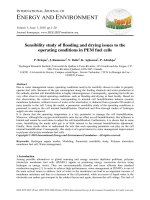
The New Museum designed by SANAA, a Tokyo architectural firm, was unveiled in New York on Dec.
1. In order to fit a vertical space in a high-density Manhattan setting, SANAA has stacked boxes,
shifted off-axis, to create a minimalist structure. The gaps created by the off-axis stacked boxes
became the skylight of galleries and the terraces of offices. The New Museum’s strong presence is
highlighted by SANAA’s exploration of boundaries between internal and external spaces, a feature
of minimalist expression. The numerous attempts that have been made to realize this project, how-
ever, offer many implications for the communication between the architects and project collabora-
tors. In order to examine the process of SANAA’s second project in the United States, Space inter-
viewed Toshihiro Oki, who was a project architect for the Toledo Museum of Art Glass Pavilion and
the New Museum. We intend to examine architectural attempts to realize a single design concept,
ranging from material selection, to solutions to details, to in-depth study of thermal energy con-
ducted to construct a glass building. <
Written by Lim Jin-young>
Kazuyo Sejima +
Ryue Nishizawa
NEW MUSEUM OF
CONTEMPORARY ART
What Completes
SANAA’s Design?
Feature 01
Edited by Lim Jin-young | Designed by Hwang Hye-rim
© Iwan Baan
Design Architect: Kazuyo Sejima + Ryue Nishizawa(SANAA)
Location: New York, USA
Principal use: contemporary art museum
Site area: 737.86m
2
Building area: 737.86m
2
Total floor area: 5,776.42m
2
Structure: Steel Frame
Design team: Florian Idenburg, Toshihiro Oki, Koji Yoshida,
Hiroaki Katagiri, Yoshitaka Tanase, (former staff-Jonas Elding,
Javier Haddad Conde, Junya Ishigami, Yoritaka Hayashi, Fenna
Haakma Wagenaar, Jamin Morrison)
Architect of Record (SD1): Guggenheimer Architects
Structural Consultant: SAPS - Sasaki and Partners / Mutsuro
Sasaki, Eisuke Mitsuda, Hajime Narukawa
Structural Engineer: Guy Nordenson and Associates
Mechanical / Electrical Engineer: ARUP
Lighting Designer: Tillotson Design Associates
Curtain Wall Consultant: Simpson Gumpertz & Heger
Client: New Museum of Art
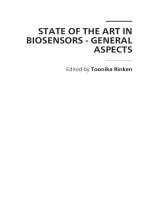
Site plan
Not wanting to create an introverted mass in a dense urban setting like Downtown Manhattan,
SANAA opened the building up and the museum started to interact with its surroundings.
7776
The New Museum of Contemporary Art is an urban infill in
Downtown Manhattan. Given such a dense urban setting, stacking
museum spaces might easily have led to an introverted mass, but by
shifting the volumes in relation to each other we opened the build-
ing up and the museum started to interact with its surroundings.
This shifting allows for skylights, terraces, and variation, all while
maximizing wall space and keeping within the zoned building enve-
lope. As the relation between core and envelope vary, different
lighting conditions and proportions arise.
Written by SANAA | Photographs by Dean Kaufman(except indicate otherwise)
© Iwan Baan
© Iwan Baan
© Iwan Baan
7978
Kazuyo Sejima received a master’s degree in architecture from Japan Womens University, and
is a professor at Keio University. Together with Ryue Nishizawa, she established SANAA in 1995,
and has ever since been carrying out active architecture work. Born in 1966, Ryue Nishizawa
received a masters degree in architecture from Yokohama National University, established the
Office of Ryue Nishizawa, and is running the firm as well as conducting SANAA-related work at
the same time. Nishizawa is also an associate professor at Yokohama National University. Their
main works include the Yokayama S House, M House, and K Building. Current projects include
the Stadstheater Almere “De Kunstlineie” in the Netherlands, an expansion project for the
Institue Valencia d’Art Modern in Spain, and the New Museum of Contemporary Art, New York.
Their awards include the Golden Lion Award at the ninth International Architecture Exhibition in
Venice in 2004, and the Armold W. Brunner Memorial Prize in 2002.
Shifting the volumes in relation to each other allows for elements such as skylights. As the relation
between core and envelope vary, different lighting conditions and proportions arise.
The gaps created by the criss-crossing of the boxes allow for elements such as terraces.
© Iwan Baan
Section 1F Plan
3F Plan
7F Plan
mechanical roof
terrace
mechanical
multipurpose room
multipurpose room
office
education
gallery
gallery
gallery
gallery
gallery
holding
lobby
gallery
gallery lobby
cafe
cafe
shop
hall
81
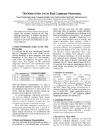
2. Program / Section diagram _ The shifting floors create moments where
the building opens up balconies, views, roof lights.
3. Moments of urban interaction1. Zoning Study _ Basic zoning makes massive static bulk
80
8382
4. Curtain wall options-details
4-1. Brick veneer_Full brick system 4-2. CMU System 4-3. Corrugated aluminum liner panel
4-4. High Performance Concrete System
5. Developing clip detail
6. Computer model to map the wind and snow/ice load
27.072
23.214
19.355
15.497
11.639
7.781
3.922
0.064
-3.794
-7.652
-11.511
-15.369
-19.227
Global Mx
(N-mm/mm)
Provided by James & Taylor
7. Fabrication of expanded metal mesh
Energy flow through the facade
240W/m
2
300W/m
2
255W/m
2
180W/m
2
56W/m
2
The massing of the building seems to be staggered;
boxes set upon boxes - they are jogged, but are also
based on proportion studies, as you mentioned
before - they reflect how SANAA engaged the
volumes programmatically?
Each program element occupies one box. The boxes
are stacked on top of each other on a tight urban site,
so the progression through the building becomes
vertical. In order for the user to have a connection
back to the city, the boxes shift back and forth and
create openings (skylights) that visually connect back
to the sky or become terraces that visually connect
back to the city. Typically in NYC, buildings are
maximized to the zoning envelope. This creates a
block volume in which the front façade becomes the
surface treatment, and the user moves through the
building with little connection to the volume of the
building. By not maximizing the zoning envelope, the
boxes were given room to shift. This then activated all
four sides of the building, creating a volumetric
shape that the user can engage. <fig. 2, 3>
It is very smart to engage the programs as
volumetric studies and relate these to zoning
requirements. How did SANAA choose the
materials for the external façade?
We’ve been researching various materials, but
originally the façade was thought of as very flat and
clean, with hardly any visible joints. The boxes had
very crisp and defined edges, but we began to realize
that this kind of precision did not fit the gritty urban
8584
Collaborators for the New Museum and
the Toledo Museum of Art Glass Pavilion
The role of the project architect is increasingly critical: As architectural practices increasingly rely on
geographically dispersed networks of collaborators and consultants, the project architect at the center of the
network increasingly must interpret the goals of the team. Moreover, this person is charged with finding and
acting preemptively to secure experts across a broader geographical industry and from an array of possible
options. This role must satisfy the needs of the client, but also those of the collaborators and the architect,
especially since primary decision-making is increasingly regulated early in the design process by cost in our
current industry. SPACE interviewed Toshihiro Oki, who worked as a project architect for the two SANAA
projects built in the U.S., namely the Toledo Museum of Art Glass Pavilion, which presented solutions to energy
problems of glass buildings to great acclaim, and the New Museum with its delicate finishing touches at work to
achieve the image of controlled boxes. Together they form a controlled architectural aesthetics unique to
SANAA. In this feature we pay attention particularly to the inside stories of the numerous studies and
experiments in the process of completing SANAA’s aesthetics.
Eunjeong Seong: Let’s start with the New Museum project in New York City.
You’ve been a project architect for two major projects in States; what differences
do you see?
Toshihiro Oki: SANAA won the New Museum competition in 2003. It was a
competition that required a proposed design, so the office had to jump right into the
design. While Toledo was horizontal and plan-driven on a spacious bucolic site, the
New Museum was vertical and volume-driven on a tight urban site. The designated
zoning envelope was very important because it defined the parameters in which the
boxes could shift. <fig. 1>
Interview Toshihiro Oki (SANAA’s New York Office) + Eunjeong Seong (New York Correspondent)
Material provided by Toshihiro Oki
INTERVIEW
In order for the user to have a connection back to the city,
the boxes shift back and forth and create openings
(skylights) that visually connect back to the sky or become
terraces that visually connect back to the city.
Toledo Museum of Art Glass Pavilion, SANAA, 2006.
The spaces, each containing a different function, are arranged and shaped to separate gently but also to connect. The "in
between"spaces, a result of the independent shapes, function as a dynamic buffer, sometimes emphasizing closeness,
something strengthening the distance.
© Christian Richters
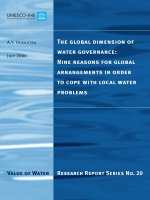
8. Plan Diagram - Process
9. Energy flow through the facade
Unconditioned cavity,
-5 C
Air heated cavity,
supply along outer
facade
Air heated cavity, air
supply along inner
facade
Radiation heating by
floor and ceiling and
reduced air rate for
cavity
Direct glass heating
and reduced air rate
for cavity
Unconditioned cavity,
-5 C
Acceptable glass
surface
temperatures in the
room
Acceptable glass
surface
temperatures in the
room
Acceptable glass
surface
temperatures in the
room
Increased glass
surface
temperatures in the
room
Limited losses through
reduced temperature
differences and
convective heat
Maximal losses through
reduced convective heat
transfer coefficient at
very cold outer facade
Slightly reduced
losses through better
resistance along the
outer glazing
Reduced losses
through reduced air
velocities and therefore
increased surface
Minimized losses and
direct heating of
critical surface
Works for cooling Works for cooling
Radiative surface can
be used for cooling or
as radiative heat sink
Limited cooling due
to reduce air flow
Analysis of energy flow through the facade _ Left lite is an exterior glass and right is an interior one. And top is ceiling and bottom is
floor. From unconditioned in interstitial space to conditioned one with heated air changed to work this space as buffer zone without too
much of loss of energy and avoid condensation.
provided by Transsolar
8786
site, nor could such precision be feasibly obtained in the current construction environment. We therefore
started broadening the search to rougher and industrial materials that could take on the site and the
environment. Eventually, we decided on expanded metal mesh. Its roughness and surface contortions had
more depth and variation, thus more possibility of rendering. This undefined blurry quality interested us.
I went down to the Museum recently and I couldn’t see the connections between the expanded metal panels.
How did SANAA make a detail that does not to show the seam between two panels - each panel must have a
limited size? How did you set your goals and form a mindset to make this understated detail?
A monolithic appearance of the mesh material over the boxes was one of the biggest goals, but mesh panels
cannot be fabricated in such large sizes; therefore, instead of fighting the fabrication system, we had to utilize it
to our benefit. However, we also realized that it doesn’t need to be the exact way the industry prescribes it. At
the beginning, everyone told us that the mesh panels should be unitized into some sort of a system, so that it is
easy to install in the field. The typical way is to mount the mesh into a frame that sets into a grid
under-structure. But we felt this defeated our intention, because this system felt so commercial, as if the
economy of the building industry were setting the parameters. So we spent a lot of time exploring how this
commercial system could be undone and redone in another simpler system that allows the mesh to be free of
any framing. This is where we developed the idea of overlapping the mesh panels at the vertical ends to create a
fish-scale type system. This overlap actually worked to the contractor’s benefit, because he could use this
overlap as a field-adjustable tolerance. Therefore, if the overall built wall dimensions were slightly off from the
constructions drawings (which happens often), the contractor could adjust each overlap slightly to still cover
from one corner of the building to another corner of the building, without having an effect on the overall
appearance of the mesh. Our decision to use the overlap made the contractor happy because he knew it would
make his installation easier, and thus less costly and problematic. We were happy because the mesh would
appear monolithic. We were both happy, and the construction proceeded smoothly, with everyone set on the
same goal.
As you mentioned earlier, New York is such a hard place to work due to all sorts of
requirements by law, difficulties like schedules, very tight working spaces, transportation
logistics, etc. - these difficulties also are related to higher costs. How did SANAA attempt to
control the costs, and still not lose the designer’s intention?
This is a good point. We knew from previous projects that a design is only as good as its
execution, so we needed to make sure that all of our designs were feasible in the New York
building environment. But again, we didn’t want to do the standard procedures, so in order to
meet design, cost, schedule and feasibility parameters, we had to analyze everything in a
matrix format, where all possible options were gauged against the parameters. For example,
with the backup wall, we were looking for a monolithic background material for the mesh, but
it needed to be simple to apply, cost-effective as a material, fire-resistant according to code,
and able to accommodate all the penetrations from the mesh attachment clips. We analyzed
many different wall options, such as high-performance concrete, insulated metal panels,
curtain wall metal panels, smooth monolithic spray membranes, concrete masonry units, and
even brick. Upon all this research, we concluded that custom extruded aluminum panels with
a small corrugated surface pattern would best perform to our criteria. The real impact came
from the fact that extrusions can be made
in any shape, since the cost is in making
the original dye. After that, you only pay for
the amount of material that is extruded.
We saw that with a little more money used
up-front to make the dye, we could make
the extruded panels that exactly fit out
specifications, without any up-charge for
the rest of the order. All the other wall
systems required a lot of effort to even
slightly modify the system, since each wall
panel would need to be modified, so the
custom-extruded panels were most
cost-effective. <fig. 4>
After several in depth research phases, it was
decided to do the rear supported panel system with
a corrugated panel. What about the connection
between the back panel and expanded aluminum
mesh?
So now we had to develop the clips to hold the
expanded mesh panels. The clip evolved from a flat
steel clip with slip connections to a round thin
diameter rod. After the full scale façade mockup was
done, we really saw that the flat steel clip was just
too much of a presence. The flat area cast shadows
on the backup wall. It gave too much of a mechanical
feel to the idea of floating mesh, so along with
McGrath (façade contractor) and James & Taylor
(engineer and supplier for the mesh), we started to
rethink the clip design. Again, cost was the biggest
parameter, but James & Taylor developed a design
that used a standard 10mm-diameter stainless steel
rod and coined the ends to make a flat surface for
riveting to the wall and mesh. The rod was much less
visible than the flat plate, and it also fit within the
budget. We also tweaked it further by placing the clip
at an angle to reduce the profile from below. <fig. 5>
What other aspects of the exterior material did you
seek - or add?
We had a number of criteria that were important to
us. They included the shape of the mesh diamonds, the size of the
diamonds and panels, fabrication tolerance of the panels, and bright,
consistent anodizing. And of course, there was schedule and cost. We
did a world search and the only fabricator who could supply mesh that
met our criteria was Expanded Metal Company teamed up with James
& Taylor. They were able to pull together their network of people whom
they’ve worked with in the past, so their team was “well-oiled.” For the
shape and size of the mesh diamond, they fabricated a custom-sized
dye to stamp the mesh to the module size that fits the building. For
fabrication tolerance, they had enough experience with this size mesh
to know how to handle the variables. Also, the anodizing was a special
method they had developed. This method produces bright anodizing
without the expensive and toxic process that the conventional method
requires. <fig. 6, 7>
I would like to talk about the other SANAA project, the Glass Pavilion, in which you participated. As an
architect myself, I can see that this project is very significant not only for the materiality of the glass and the
reflected landscape inside of the building, but also because it gives us a new paradigm, or form, for the plan
drawing. The cavity space in the Glass Pavilion expands and contracts to organize the main spaces. It allows
us to read the drawing in a completely opposite way, meaning we pay attention to the cavity space in a way
that we never would have in the conventional drawings. The effect of this is a very enigmatic spatial quality
that we’ve never experienced before. You are almost always faced with two or more layered surfaces of
straight and curved glass. The different distances between the surfaces and the different degrees of
curvature of the glass continually expand and contract the cavity space. Can you describe how SANAA
approached this project, in brief?
In 2001, the Toledo Museum of Art selected SANAA to design a new building to house their
extensive glass collection. The selection process was unique in that the museum’s criteria were
based on the type of office they would like to work with, as opposed to a presented competition
scheme. By doing this, the design developed and evolved, with the museum as a partner from the
very beginning. The Toledo museum complex includes a Beaux-Arts style art museum built in the
early 1900’s, as well as the University of Toledo’s Center for Visual Arts, designed by Frank Gehry.
There are also some connecting green areas with tall old growth trees that create a rather bucolic
setting. We selected the site of the Glass Pavilion by combining one of the existing parking lots and
a grove of this tall, centennial oak tress. The Pavilion actually sits where the parking lot used to be,
and slides right under the leaf canopy of the oak trees. None of the trees were disturbed. And by
keeping the building as a one-story structure, the neighbor’s sight lines to the museum were kept
intact. The intention was to ease naturally into the site, without much disruption.
The site could make it difficult to produce order during an architectural process. Can you
describe how SANAA organizes the spaces and this type of a unique plan?
The museum program was laid out in concordance with the adjacency requirements serving as a
guide. This caused the layout to gravitate to a certain configuration. Thinking about movement
between spaces, we realized that diagonal
connections at the corners allowed more
flexibility in circulation. This diagonal
connection led to curved corners, which in
turn led to the idea that each space would
have its own walls. Typically, two adjacent
spaces share a wall in-between, but this
locks the spaces together, since the dividing
wall dictates the division. By giving each
space its own independent walls, the spaces
could then slide past each other in a more
fluid manner. Also, you could actually move
from one space to the next without actually
leaving the room, through doors. The
resultant cavity space became a thermal
buffer zone, like an expanded IGU
(Insulating Glass Unit). This thermal buffer
was critical in allowing the use of all glass
walls. Without it, the concept of all-glass
walls could not work. It is funny, but the
plan drawing showing the cavity walls confused some
publications. A few editors wrote back, asking us to
show the wall thickness because they couldn’t find
the typical thick wall lines (laugh). <fig. 8>
Are you saying the cavity space wasn’t thought
about from the start?
SANAA didn’t start with a preconceived form. The
process of figuring out the program produced the
form as you see it now. It was process-driven.
The entire exterior wall is, of course, glass. Can we
talk about the material itself in more detail?
There were two important engineering aspects about
the reality of using glass. One was to make the
thermal buffer cavity zone work with all glass walls,
and the other was to create a thin roof supported by
invisibly thin columns, so that it makes the roof
appear to float above the glass walls. The exterior
walls are all glass panels made up of
+
low-iron laminated annealed glass with a PVB
(polyvinyl butyral) interlayer. The joints between the
There was a lot of
research and testing done
to integrate the curtains
into the mechanical
system while still keeping
to the design intentions
of the building.
10. Energy flow through the facade
11. Study of location of shading device for
reducing amount of heat gain along the idea of
radiant heat and low velocity airflow analysis.
12. Daylighting Sun study 13. Curtain mock up 14. Mock up Test
Environmental design/CFD Thermal Analysis(Provided by Transsolar, Stuttgart, Germany) _ While the pure air solution increased
the heat losses due to the increase surface losses, an alternate solution with heat supply by radiation through the floor and ceiling
surfaces, should allow to temper the facade buffer without huge air rates. Temperature on floor and ceiling in cavity: 35°C, reduced
supply air in cavity: 1 m/s or 5 ac/h The heat supply by radiation heats the glass surfaces not by the air, but in a direct path.
Therefore the air temperature in the cavity can be reduced to 12.5°C and with the only minimal reduced surface resistances, the
heat losses through the facade drop to 180 W/m
2
or by 40%. The inner surface temperatures facing the room keep the level of 15
-25°C, out of the condensation range.
Aside of the balance method the CFD evaluations confirmed the approach to reduce the air flow rate through the radiant system .
by factor 4! -, with strong consequences for the size of the ducts, solving strong conflicts with the structural concept. As a side
effect, the radiant heating system can be used in summer as a radiant cooling system, absorbing radiation before it heats the air
and has to be removed by an air flow.
provided by Transsolar
provided by ARUP Lighting
without shading
with internal shading with cavity shading
8988
glass panels are
wide silicon joints, with a clear gasket spacer inside to keep the silicone and
PVB separated. Silicone can cause PVB to become delaminated. The flat glass panels follow the
8
-0
building grid, so one size fit all straight wall locations. The curved panels were categorized into
set radii and perimeter lengths, keeping the number of slumping molds to a minimum in order to
control cost.
As you mentioned earlier, the cavity space is making a significant contribution as a thermal buffer. Can you
talk about the cavity space in terms of mechanical engineering? How did you address the thermal issues of
the interstitial space?
While the transparency of glass allows the visitor to see from one space to the next, it also allows thermal
energy and sunlight to enter into the building; therefore, an engineered analysis needed to be done to
understand the parameters and what options were available to control these. For example, the cavity space
was analyzed with different thermal concepts. These five diagrams show these concepts, with calculated
thermal movement between the exterior and the interior. <fig. 9>
A series of options seem to have been very carefully done with this expertise. Matthias
Schuler of Transsolar stated that the building was impossible to execute without this kind
of engineering support. It is truly a great collaboration with consultants who seem far more
like full-fledged collaborators. What is the general mechanical concept?
Yes, we were lucky to have Transsolar. Matthias is like a mad scientist, but his creativity of
thinking is what allowed new thermal concepts to develop, thus allowing our design to
become a reality. Also, we were operating under a tight budget, so the design not only had to
be feasible, but also cost efficient. Using the cavity concept, Transsolar used CFD
(computational fluid dynamics) <fig. 10> thermal analysis to conclude that a combined
system of radiant heating-cooling and low velocity air flow was the most efficient way to
utilize the buffer between the all glass walls. This system allows the interior spaces to
remain at the required temperature, while eliminating condensation on the glass and the
need to pump a lot of heated air into the cavity. In other words, the cavity can act as a buffer,
instead of a siphon. In addition, the Hot Shop spaces - where visiting artists blow glass and
hold classes or demonstrations - provide a lot of excess heat that is in turn pumped back into
the building systems for reuse. The gallery spaces are zoned separately from the Hot Shops
due to different temperature and humidity requirements. The galleries have floor air supply
diffusers towards the middle of the spaces and 1” wide return air gaps between the glass
walls and the ceiling, along the perimeters. This allows for proper air circulation.
There is a now relatively new book titled “Inside Outside” by Petra Blaisse. She showed the Glass Pavilion
project in a significant way, not only for the energy issues and solutions, but also the client’s need to separate
the programmatic spaces on demand. From an engineering aspect, are these curtains related to heat
transfer?
There was a lot of research and testing done to integrate the curtains into the mechanical system while still
keeping to the design intentions of the building. Transsolar’s thermal analysis showed that the position of the
curtains within the cavity space had a critical impact on heat gain through the glass. <fig. 11> Also, the overall
locations of the curtains were based on ARUP
Lighting’s sun-shading studies, showing how direct
sunlight enters into the building over the four
seasons. <fig. 12> Furthermore, the transparency
level of the curtain fabric was informed by the level of
sunlight (measured in foot candles) that entered into
the various spaces. Also, the curtain fabric was
specially chosen - an aluminized fabric made by a
Swiss company, called Verosol. This fabric helps
direct thermal gain back out of the building, creating
an appropriate ambient environment for the
museum’s glass artwork. The combinations of these
techniques were necessary to meet the museum’s
requirements. Then, as the curtains went into the
execution phase, we looked at many different
seaming and attachment methods to find the right
feel to the curtains. All of the vertical curtain seams
were aligned to the glass wall joints to reduce the
amount of visual lines. <fig. 13, 14>
What is the general idea of structure, since there
are two significant elements prevalent, such as thin
columns and roof? (This question was answered by
Brett Schuneider of Guy Nordenson Associates.)
Brett Schuneider: Two things. The first is to
understand that we collaborated with Sasaki
Structural Consultants (Masohiro Sasaki), who have
a long relationship with SANAA and helped develop
the concept for the project. Second, the project can
be defined initially as a simple cartoon consisting of a
single line of the roof and single line of the
floor/ground with glass between - the concept is
simple, and therefore open to interpretation and
development (as initiated by SANAA). Sasaki’s idea
was to apply a structure similar to that of the Sendai
Mediateque in Japan - a stiffened steel plate to
provide as thin a roof structure as possible. Some
initial ideas that we pursued were to use the
perimeter glass for partial gravity support. So while
the implied goal was the minimization of the
columns, it was clear that the main goal was the
thinness of the roof. In order to achieve this in
America (where the Sendai system would be considered radical construction), we began a systematic
development of applicable framing systems for comparison - all based on the principle of approaching
equivalent flat plate two-way behavior. These systems included top steel plate stiffened by wide flange sections
below, and more typical wide flange framing at varied spacing with metal deck above. The economics of the
systems studied resulted in the flat frame of wide flange steel sections used in the final design. The entire
frame is moment-connected to make both the girders (East-West) and joists (North-South) continuous allowing
reduced depth of the framing overall. The girders follow snaking lines connecting the columns, with the joists
straight and regularly spaced between. The kinks in the girders occur at locations of joists framing in, so that
the resulting torsion of the kink is resolved cleanly in bending in the joists.
The columns are located generally in the cavities between rooms (where possible) - locating the columns
generally came after the design of the rooms (for the most effective functioning of those rooms). It was never
clearly discussed, as such and early schemes show a much more regular arrangement, but the final location of
the columns is not on any regular grid. This is important because there is no discernable pattern to their
placement to be perceived, and thus they tend to disappear. I often refer to them as "hiding in plain sight." In
addition, the columns have pins at their tops to allow rotation along the axis of the girders, so as to prevent the
transmission of bending and allow the columns to be smaller, and the majority of the building’s lateral stiffness
is in the exposed steel plate walls of the Lampworking Room (steel plate shear walls where flat and effective
columns where the wall is curved) - another example of structure in plain sight that you might not easily
recognize (even though you see its thickness clearly where the window is inset into it). The coordination of the
systems was the most difficult part of the technical process and required extraordinary coordination and
collaboration between designers. The roof framing at its deepest is 15" (375mm), and the structure shares
depth with the mechanical systems below (air, roof drainage, and sprinklers) and the roof insulation above. The
girders are 12-15" deep and extend up into the roof insulation when greater than 12", and the roof framing as a
whole is penetrated and hunched to allow the passage of air,
sloped drainage pipes, and sprinklers as necessary. The
interaction is so complex that every beam was elevated to
accurately document all of the penetrations. <fig. 15, 16, 17,
18, 19, 20,>
Everything is thought out; there is not a single item left out.
Brett Schuneider talked earlier a little bit about two aspects
of engineering for this building. What are the specific
engineering aspects that you want to talk about? There was
a goal to keep the roof very thin, but SANAA also located
major mechanical systems - heating, ventilation, plumbing -
that made this difficult. What was the experience to design
such a roof structure like?
We felt we needed to fully understand all the components of the system in order to make sure everything
possible was done to lighten the appearance of the roof. Everything was double and triple checked then
re-questioned until the engineers turned blue in their faces. I supposed people thought we had gone mad, but
we wanted to make sure it was not 99.99% but really 100%. To further keep a thin roof, all mechanical piping,
roof drains, sprinkler lines etc. were pushed up in-between the structural roof members, and beam
penetrations were employed to move the
piping from one structural bay to the next.
Then a further layer of coordination was
required between the structure, MEP,
roofing, and glass walls. While sprinkler
lines are pressurized and thus can all run at
one elevation, roof drains require a certain
slope to allow collected rain water to run in
the correct direction. But this meant that
every time a drain penetrated a beam along
its sloped run, it would penetrate at a
different and lower elevation; therefore, all
the penetration holes needed to be marked
with specific elevations, so that each drain
line could maintain its required slope. This
was a very difficult exercise to control while
keeping in mind the fabrication and
installation tolerance of steel.
The scope of global industries that have been
engaged at both Toledo and New York is relied upon
as a network of specialists that SANAA helped find
and coordinate. Also, as mentioned earlier, the
relationship with the consultants seems like a very
coordinated give and take; SANAA’s coordination is
far more extensive than the normal, and it is very
much at the core of the project’s potential. The
development of Internet communications and
globalization has allowed your teams to work
together without having easy geographical
proximity.
At SANAA, we spend a tremendous amount of time
researching, but also engaging enthusiastic and
intelligent consultants/engineers/fabricators gives
us new motivation for design, too.
The consultants all mentioned that the architects
gave them new challenges in new realms of work.
Thanks so much for your time and hopefully we’ll
see you with a different project in future SPACE
magazines.
At SANAA, we spend a tremendous
amount of time researching, but
also engaging enthusiastic and
intelligent consultants/ engineers
/fabricators gives us new
motivation for design, too.
15. Superstructure Finite-Element Analysis Model
provided by Guy Nordenson and Associates
provided by Guy Nordenson and Associates
provided by Guy Nordenson and Associates
provided by Guy Nordenson and Associates
16. Superstructure Construction Photograph 17. Typical Roof Section and Construction Photograph of Typical Roof Girder
18. Typical Column Head Detail and 3d Solid Finite-Element Analysis Model of
Bearing at Pin Through Top of Column
19. Pipes penetrate through beams 20. Glass Installation