fbl brushless motor
Bạn đang xem bản rút gọn của tài liệu. Xem và tải ngay bản đầy đủ của tài liệu tại đây (521.6 KB, 12 trang )
B-34
ORIENTAL MOTOR GENERAL CATALOG 2003/2004
Specifications B-36
Characteristics B-37
System Configuration B-35Features B-34
Specifications B-36
Characteristics B-37
System Configuration B-35Features B-34
Speed Control Systems
Brushless DC Motor Systems
FBL2 Series
The FBL2 Series consists of a high performance, compact,
brushless DC motor and driver. This product is available with
75 W (1/10 HP) and 120 W (1/6 HP) output power.
For easy installation, the combination type (pre-assembled
gearmotors) comes with the motor and gearhead already
assembled.
Combination Type (Pre-assembled Gearmotors)
The combination type (pre-assembled gearmotors) come with the
motor and its dedicated gearhead already assembled. This simplifies
installation in equipment. Motors and gearheads are also available
separately so they can be on hand to make changes or repair.
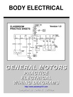
Ⅵ Features
ⅷ Compact and High Power
The use of brushless DC motor greatly reduces the total
motor length while achieving high power. The FBL2 outputs
a high power of 120 W (1/6 HP) with a frame size of 3.54 in.
sq. (90 mm sq.) and a total length of 3.15 in. (80 mm),
allowing to easily downsize applications.
ⅷ Excellent Speed Stability
The FBL@ Series offers excellent speed fluctuation
characteristics. Speed fluctuation is only minimally affected
by the load.
Speed regulation: with load Ϫ1% maximum,
with voltage Ϯ1% maximum,
with temperature Ϯ1% maximum
□ 3.54 in.
(□ 90 mm)
3.15 in. (80 mm)
FBL5120
Output
Power
120 W (1/6 HP)
Ⅵ Safety Standards and CE Marking
✽ The three-phase 200-230 VAC type conforms to EN standards.
● Details of Safety Standards➝Page G-2
● When the system is approved under various safety standards, the model names in the motor and driver nameplates are the approved
model names.
List of Motor and Driver Combinations ➝ Page B-43
CE Marking
Standards File No.
Certification Body
Standards
Low Voltage Directives
E62327UL
UL1004
Motor
CSA C22.2 No.100
124888DEMKOEN60950
EN60034-1
EN60034-5
E171462UL
UL508C
Driver CSA C22.2 No.14
131974DEMKO
EN60950
✽
Conform to EN/IEC Standards
ⅷ Wide Range of Speed Control
In addition to offering a wide speed control range from 300
r/min to 3000 r/min, the motor generates constant torque
across the entire speed range.
ⅷ Acceleration and Deceleration Function
The driver is provided with an acceleration/deceleration
function which makes it possible to smoothly start and stop
the motor.
ⅷ High Strength Gearheads
Pre-assembled gearmotors use specifically designed high
strength GFB gearheads, providing torque of up to 260 lb-in
(30 N·m).
ORIENTAL MOTOR GENERAL CATALOG 2003/2004
B-35
Dimensions B-38
Connection and Operation B-40
Motor and Driver Combinations B-43
Dimensions B-38
Connection and Operation B-40
Motor and Driver Combinations B-43
Speed Control Systems
Brushless DC Motor Systems
DC Input
AC Motor Systems
BX
FBL2
AXU
AXH
BHF ES
US
Introduction
Before Using a
Speed Control
System
AC Input
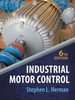
Ⅵ System Configuration
Mounting Brackets
(Accessories)
(➝Page A-204)
Driver
FBL
2 Series
Flexible Couplings
(Accessories)
(➝Page A-208)
Extension Cables
✽1
(Accessories)
(➝Page B-44)
✽
2
(Not Supplied)
(Not Supplied)
(Not Supplied)
External
Speed
Potentiometer
(Included)
DIN Rail Mounting Plate
(Accessories)
(➝Page A-217)
Motor Speed Indicator (Accessories)
✽ Not a standard certified product
(➝Page A-214)
Combination Type
(Pre-assembled Gearmotor)
AC
Power Supply
Programmable
Controller
24 VDC
Power Supply
✽2
The system configuration shown is an example. Other configurations are available.
Required when the
driver’s built-in power
supply is not used.
✽1
A flexible extension cable is available for
FBL@ Series. It is most suitable for uses
where the cable is bent, twisted or
rotated. (
➝Page B-44)
Ⅵ Product Number Code
FBL 5 75 A W - 5
Number: Gear Ratio
A: Round Shaft Type
W: Meets Safety Standards
Voltage A: Single-Phase 100-115 VAC
C: Single-Phase 200-230 VAC
S: Three-Phase 200-230 VAC
Output Power 75: 75 W (1/10 HP)
120: 120 W (1/6 HP)
Motor Frame Size 5: 3.54 in. sq. (90 mm sq.)
Series
FBL : FBL2Series
Ⅵ Product Line
ⅷ Combination Type ⅷ Round Shaft Type
●
Enter the gear ratio in the box (Ⅺ) within the model name.
Gear RatioModelPower Supply Voltage
Output Power
HP W
1/10 75
5, 10, 15, 20,
30, 50, 100, 200
FBL575AW-Ⅺ
FBL575SW- Ⅺ
FBL5120AW- Ⅺ
FBL5120CW-Ⅺ
FBL5120SW-
5, 10, 15, 20,
30, 50, 100, 200
5, 10, 15, 20,
30, 50, 100, 200
5, 10, 15, 20,
30, 50, 100, 200
FBL575CW-
5, 10, 15, 20,
30, 50, 100, 200
5, 10, 15, 20,
30, 50, 100, 200
Ⅺ
Single-Phase
Three-Phase
Single-Phase
Single-Phase
Three-Phase
100-115 VAC
ⅪSingle-Phase 200-230 VAC
200-230 VAC
100-115 VAC
200-230 VAC
200-230 VAC
1/6 120
FBL575AW-A
FBL575CW-A
FBL575SW-A
FBL5120AW-A
FBL5120CW-A
FBL5120SW-A
100-115 VAC
200-230 VAC
200-230 VAC
100-115 VAC
200-230 VAC
200-230 VAC
ModelPower Supply Voltage
Single-Phase
Single-Phase
Three-Phase
Single-Phase
Single-Phase
Three-Phase
Output Power
HP W
1/10 75
1/6 120
B-36
ORIENTAL MOTOR GENERAL CATALOG 2003/2004
Specifications B-36
Characteristics B-37
System Configuration B-35Features B-34
Specifications B-36
Characteristics B-37
System Configuration B-35Features B-34
Speed Control Systems
FBL5120CW-Ⅺ
FBL5120CW-A
1.8
2.7
56 (0.4)
71 (0.5)
30 (5.6)
✽ The permissible load inertia specified above is only applicable for round shaft type. Permissible Load Inertia for Combination Type ➝ Page B-37
● Enter the gear ratio in the box (Ⅺ) with the model name.
● The values for each item is for the motor only.
1/10 (75) 1/6 (120)
FBL575CW-Ⅺ
FBL575CW-A
1.4
2.0
35 (0.25)
45 (0.32)
20 (3.75)
FBL575SW-Ⅺ
FBL575SW-A
0.75
1.2
Model
Rated Output Power
Power Source
Rated Torque
Starting Torque
Permissible Load Inertial J
✽
Rated Speed
Variable Speed Range
Speed Regulation
50/60 Hz
3000
300ϳ3000
Ϫ1% Max. (0ϳrated torque, at 3000 r/min)
Ϯ1% Max. (Power supply voltage Ϯ10%, at 3000 r/min with no load)
Ϯ1% Max. [32°Fϳ122°F (0°Cϳϩ50°C) at 3000 r/min with no load]
Combination Type
Round Shaft Type
HP (W)
Voltage
Frequency
Rated Input Current A
Maximum Input Current
A
oz-in (N·m)
oz-in (N·m)
oz-in
2
(ϫ10
-4
kg·m
2
)
r/min
r/min
Load
Voltage
Temperature
FBL575AW-Ⅺ
FBL575AW-A
2.3
2.6
Single-Phase
100-115 VACϮ10%
Single-Phase
200-230 VACϮ10%
Three-Phase
200-230 VACϮ10%
Single-Phase
200-230 VACϮ10%
Three-Phase
200-230 VACϮ10%
FBL5120SW-Ⅺ
FBL5120SW-A
1.0
1.6
FBL5120AW-Ⅺ
FBL5120AW-A
3.0
3.8
Single-Phase
100-115 VACϮ10%
Ⅵ Common Specifications
✽1 With the FBL2 Series, motor speed cannot be controlled in applications where the motor's shaft is turned by the load, as in lowering operations. Also, to prevent
damage to the driver during lowering operations, if the primary voltage of the driver's inverter exceeds the permissible value, the protection circuit engages and the motor
comes to a natural stop.
✽2 Motor insulation is recognized as Class A [221°F (105°C)] by UL and CSA standards.
Item
Any one of the following methods
1. By built-in potentiometer (1 piece) 2. By external potentiometer (20 kΩ 1/4 W) 3. By DC voltage control (0ϳ5 VDC)
Speed Control Method
Input Signal
Photocoupler Input
Input Impedance 4.8 kΩ 24 VDCϮ10%
Common to EXT. VR., CW, CCW, SLOW DOWN
Open Collector Output External Use Condition 26.4VDC, 10 mA Max.
Common to SPEED OUT, ALARM OUT
Output Signal
Protection Functions
✽1
When the following are activated, the alarm signal will be output and the motor will come to a natural stop:
● Overload Protection: Activated within approximately 5 seconds of the motor load exceeding rated torque.
● Overheat Protection: Activated when the temperature of the heat sink inside driver exceeds approximately 194°F (90°C).
●
Overvoltage Protection: Activated when driving a load exceeding the permissible load inertia, or when motor speed is increased due to gravitational forces.
● Undervoltage Protection: Activated when an input voltage to the driver is less than the specified voltage (Ϫ10%).
● Out-of-phase Protection: Activated when the sensor wire inside the motor cable is disconnected.
Class E [248°F (120°C)]
Motor Insulation Class
✽2
0.5ϳ15 sec. (at 3000 r/min)
Acceleration/Deceleration Time
ContinuousRating
Specifications
Ⅵ General Specifications
DriverMotorItem
100 MΩ or more when 500 VDC megger is applied between the power supply input
terminal and the Protective Earth terminal, between the power supply input terminal
and I/O terminal after continuous operation under normal ambient temperature and humidity.
100 MΩ or more when 500 VDC megger is applied between the
windings and the frame under normal ambient temperature and
humidity.
Sufficient to withstand 1.8 kV (3 kV) at 50 Hz applied between the
power supply input terminal and the Protective Earth terminal
(I/O terminal) for 1 minute after continuous operation under normal
ambient temperature and humidity.
Sufficient to withstand 1.5 kV at 50 Hz applied between the windings
and the frame for 1 minute after continuous operation under normal
ambient temperature and humidity.
32°Fϳ122°F (0°Cϳϩ50°C) (nonfreezing)
85% maximum (noncondensing)
No corrosive gases or dust
IP10IP40Degree of Protection
Insulation Resistance
Dielectric Strength
Operating
Environmental
Conditions
Atmosphere
Ambient Humidity
Ambient Temperature
Ⅵ Specifications
RrDC
ORIENTAL MOTOR GENERAL CATALOG 2003/2004
B-37
Dimensions B-38
Connection and Operation B-40
Motor and Driver Combinations B-43
Dimensions B-38
Connection and Operation B-40
Motor and Driver Combinations B-43
Speed Control Systems
Brushless DC Motor Systems
DC Input
AC Motor Systems
BX
FBL2
AXU
AXH
BHF ES
US
Introduction
Before Using a
Speed Control
System
AC Input
Ⅵ Gearmotor — Torque Table
1.5ϳ15
200
260
30
260
30
3ϳ30
100
190
21.5
260
30
6ϳ60
50
95
10.8
152
17.2
10ϳ100
30
57
6.5
91
10.3
15ϳ150
20
39
4.5
63
7.2
20ϳ200
15
30
3.4
47
5.4
30ϳ300
10
20
2.3
31
3.6
Speed Range r/min
Model
Gear Ratio
FBL575AW-Ⅺ
FBL575CW-Ⅺ
FBL575SW-Ⅺ
FBL5120AW-Ⅺ
FBL5120CW-Ⅺ
FBL5120SW-Ⅺ
60ϳ600
5
9.7
1.1
15.9
1.8
● Enter the gear ratio in the box (Ⅺ) within the model name.
● A colored background indicates gear shaft rotation in the same direction as the motor shaft; a white background indicates rotation in the opposite direction.
Unit ϭ Upper values: lb-in/Lower values: N
.
m
Ⅵ Permissible Overhung Load and Permissible Thrust Load
ⅷ Combination Type
● Enter the gear ratio in the box (Ⅺ) within the model name.
Permissible Thrust Load
Permissible Overhung Load
Gear RatioModel
0.79 in. (20mm) from shaft end0.39 in. (10 mm) from shaft end
Nlb.lb.Nlb.
15033
N
90
112
146
400
500
650
67
90
112
300
400
500
5
10ϳ20
30ϳ200
FBL575AW-Ⅺ
FBL575CW-Ⅺ
FBL575SW-Ⅺ
FBL5120AW-Ⅺ
FBL5120CW-Ⅺ
FBL5120SW-Ⅺ
Ⅵ Permissible Load Inertia J for Combination Type
ⅷ Round Shaft Type
●
Permissible Thrust Load: Avoid thrust loads as much as possible.
If thrust load is unavoidable, keep it to no more than half the motor weight.
Permissible Overhung Load
Model
0.79 in. (20 mm) from shaft end0.39 in. (10mm) from shaft end
N
33
38
lb.Nlb.
150
170
29
36
130
160
FBL575AW-A
FBL575CW-A
FBL575SW-A
FBL5120AW-A
FBL5120CW-A
FBL5120SW-A
● Enter the gear ratio in the box (Ⅺ) within the model name.
Gear Ratio
Model
51015203050100 200
137
25
550
100
1230
225
2200
400
4900
900
13700
2500
13700
2500
13700
2500
FBL575AW-Ⅺ
FBL575CW-Ⅺ
FBL575SW-Ⅺ
FBL5120AW-Ⅺ
FBL5120CW-Ⅺ
FBL5120SW-Ⅺ
Unit ϭ Upper values: oz-in
2
/Lower values: ן10
-4
kg·m
2
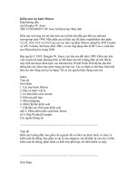
Ⅵ Speed
— Torque Characteristics (The characteristics shown below are only applicable for the motors only.)
0
0.5
0.4
0.3
0.2
0.1
0
1000
2000 3000
300
0
10
20
30
40
50
60
70
Torque
Speed [r/min]
Continuous Duty Region
Limited Duty Region
Starting Torque
Rated Torque
[oz-in]
[N•m]
0 30002000
1000300
0.4
0.3
0.2
0.1
0
Torque
Speed [r/min]
Continuous Duty Region
Limited Duty Region
Starting Torque
Rated Torque
0
10
20
30
40
50
[oz-in]
[N•m]
FBL5120AW-Ⅺ/FBL5120CW-Ⅺ/FBL5120SW-
□
FBL5120AW-A/FBL5120CW-A/FBL5120SW-A
FBL575AW-Ⅺ/FBL575CW-Ⅺ/FBL575SW-Ⅺ
FBL575AW-A/FBL575CW-A/FBL575SW-A
ⅷLimited Duty Region
This region is used primarily when accelerating. When a load
that exceeds the rated torque is applied continuously for
approximately 5 seconds, overload protection is activated and
the motor comes to stop.
ⅷContinuous Duty Region
Continuous operation is possible in this region.
B-38
ORIENTAL MOTOR GENERAL CATALOG 2003/2004
Specifications B-36
Characteristics B-37
System Configuration B-35Features B-34
Specifications B-36
Characteristics B-37
System Configuration B-35Features B-34
Speed Control Systems
Ⅵ Dimensions Scale 1/4, Unit = inch (mm)
Mounting screws are included with the combination type. Dimensions for screws➝ Page B-133
Enter the gear ratio in the box (Ⅺ) within the model name.
ⅷ Motor/Gearhead
FBL575AW-Ⅺ, FBL575CW-Ⅺ, FBL575SW-Ⅺ (Combination Type)
Motor:
FBLM575W-GFB
Gearhead: GFB5GⅪ
Weight: 6.6 lb. (3.0 kg) included gearhead
d A204A (GFB5G5ϳ20)
A204B (GFB5G30ϳ100)
A204C (GFB5G200)
ⅷ Motor/Gearhead
FBL5120AW-Ⅺ, FBL5120CW-Ⅺ, FBL5120SW-Ⅺ (Combination Type)
Motor:
FBLM5120W-GFB
Gearhead: GFB5GⅪ
Weight: 8.8 lb. (4.0 kg) included gearhead
d A205A (GFB5G5ϳ20)
A205B (GFB5G30ϳ100)
A205C (GFB5G200)
FBL575AW-A, FBL575CW-A, FBL575SW-A
(Round Shaft Type)
Motor:
FBLM575W-A
Weight: 3.3 lb. (1.5 kg)
d A206
FBL5120AW-A, FBL5120CW-A, FBL5120SW-A (Round Shaft Type)
Motor:
FBLM5120W-A
Weight: 5.5 lb. (2.5 kg)
d A207
2.24 (57)
0.39 (10) 0.20 (5) 0.98
(25)
L
1.65 (42)
1.57
(
40)
0.335 (
8.5) Ϫ4 Holes
□
3.54 (
□
90)
Housing: 5557Ϫ12R (MOLEX)
Cable
0.31 (
8),
20 inch (500 mm) Length
1.30
(33)
0.55
(14)
1.06
(27)
0.71 (18)
(
18
Ϫ
0.018
)
0
Ϫ0.0007
0
0.7087
4.09
Ϯ0.02
(104
Ϯ0.5
)
GFB5G5ϳ20: L = 1.77 (45)
GFB5G30ϳ100: L = 2.28 (58)
GFB5G200: L = 2.52 (64)
ⅷKey and Key Slot
(
Scale 1/2
)
(The key is provided with the gearhead.)
0.984
Ϯ0
.008
(25
Ϯ0.2
)
0.2362Ϫ0.0012
(6
Ϫ0.03
)
0
0
0.2362
ϩ0.0016
(6
ϩ0.040
)
0
0
0.2362Ϫ0.0012
(6
Ϫ0.03
)
0
0
0.138
ϩ0.004
(3.5
ϩ0.1
)
0
0
0.35 (9)
□
3.54 (
□
90)
2.24 (57)
1.46 (37)
1.18
(30)
0.39 (10)
0.08
(2)
0.335 (8.5) Ϫ4 Holes
Housing: 5557Ϫ12R (MOLEX)
Cable
0.31 (
8),
20 inch (500 mm) Length
1.06
(27)
1.30
(33)
0.55
(14)
(
10
Ϫ
0.015
)
0
Ϫ
0.0006
0
0.3937
(
83
Ϫ
0.035
)
0
Ϫ
0.0014
0
3.2677
4.09
Ϯ0.02
(104
Ϯ0.5
)
3.15 (80)
0.39(10)
L
1.65 (42)
1.57
(
40)
0.71 (18)
0.20(5) 0.98
(25)
Housing: 5557Ϫ12R (MOLEX)
Cable
0.31 (
8),
20 inch (500 mm) Length
1.30
(33)
0.55
(14)
(
18
Ϫ
0.018
)
0
Ϫ
0.0007
0
0.7087
GFB5G5ϳ20: L = 1.77 (45)
GFB5G30ϳ100: L = 2.28 (58)
GFB5G200: L = 2.52 (64)
0.335 (8.5) Ϫ4 Holes
□
3.54 (
□
90)
1.06
(27)
4.09
Ϯ0.02
(104
Ϯ0.5
)
ⅷKey and Key Slot
(
Scale 1/2
)
(The key is provided with the gearhead.)
0.984
Ϯ0
.008
(25
Ϯ0.2
)
0.2362Ϫ0.0012
(6
Ϫ0.03
)
0
0
0.2362
ϩ0.0016
(6
ϩ0.040
)
0
0
0.2362Ϫ0.0012
(6
Ϫ0.03
)
0
0
0.138
ϩ0.004
(3.5
ϩ0.1
)
0
0
3.15
(
80
) 1.46
(
37
)
0.43
(
11
)
1.18
(
30
)
0.39
(
10
)
0.08
(
2
)
1.30
(
33
)
0.55
(
14
)
1.06
(
27
)
(
12
Ϫ
0.018
)
0
Ϫ
0.0007
0
0.4724
(
83
Ϫ
0.035
)
0
Ϫ
0.0014
0
3.2677
□
3.54 (
□
90)
0.335 (8.5) Ϫ4 Holes
4.09
Ϯ0.02
(104
Ϯ0.5
)
Housing: 5557Ϫ12R (MOLEX)
Cable
0.31 (
8),
20 inch (500 mm) Length
ORIENTAL MOTOR GENERAL CATALOG 2003/2004
B-39
Dimensions B-38
Connection and Operation B-40
Motor and Driver Combinations B-43
Dimensions B-38
Connection and Operation B-40
Motor and Driver Combinations B-43
Speed Control Systems
Brushless DC Motor Systems
DC Input
AC Motor Systems
BX
FBL2
AXU
AXH
BHF ES
US
Introduction
Before Using a
Speed Control
System
AC Input
ⅷ Driver
FBLD75AW, FBLD75CW, FBLD75SW, FBLD120AW, FBLD120CW, FBLD120SW
Weight: 1.8 lb. (0.8 kg)
d A283
M3Ϫ4 Places
M3Ϫ12 Places
M4
0.39
(
10
)
0.98
(
25
)
5.28
(
134
)
0.24
(
6
)
1.77
(
45
)
5.91
(
150
)
2.32
(
59
)
0.98
(
25
)
0.39
(
10
)
0.39
(
10
)
4.72
(
120
)
0.67 max.
(
17
)
0.30
(
7.62
) P
itch
0.25
(
6.32
)
0.30
(
7.62
) P
itch
0.25
(
6.32
)
0.35
(
9
)
3.50
(
89
)
0.98
(
25
)
0.91
(
23
)
0.35
(
9
)
Metric Tap M3 P0.5
Ϫ7 Places
Metric Tap M3 P0.5
Ϫ2 Places
ⅷ External Speed Potentiometer (included) (Scale 1/2)
PAVR-20KZ
0.37
(
9.5
)
0.59
(
15
)
0.12
(
3
)
(
Screw
)
Knob
Dial plate
□
1.57 (
□
40)
t=0.02 (0.5)
Insulated sheet
□
1.57 (
□
40)
t=0.02 (0.5)
Potentiometer
1.57
(
40
)
0.30
(
7.5
)
0.49
(
12.5
)
1.57
(
40
)
Insulated sheet
0.12
Ϯ0.008
(
3
Ϯ0.2
)
0.37
Ϯ0.008
(
9.5
Ϯ0.2
)
1.18 min.
(
30
)
0.79
(
20
)
0.79
(
20
)
M4 P0.7ϫ
0.11
(
2.8
)
0.24
(
6
)
ⅷ Driver Base Mounting Bracket Tab
(1 set of 2 pieces included)
0.14
(
3.5
)
Ϫ2 Places Countersink
1.77
(
45
)
0.98
(
25
)
0.79
(
20
)
0.39
(
10
)
1.77
(
45
)
0.98
(
25
)
0.79
(
20
)
0.39
(
10
)
0.18
(
4.5
)
0.79
(
20
)
0.79
(
20
)
0.12
(
3
)
ⅷ Driver Back Mounting Tab (included)
0.14
(
3.5
)
Ϫ4 Places Countersink
1.77
(
45
)
0.39
(
10
)
0.98
(
25
)
0.39
(
10
)
0.18
(
4.5
)
7.87
(
200
)
0.39
(
10
)
0.39
(
10
)
1.22
(
31
)
5.28
(
134
)
1.38
(
35
)
B-40
ORIENTAL MOTOR GENERAL CATALOG 2003/2004
Specifications B-36
Characteristics B-37
System Configuration B-35Features B-34
Specifications B-36
Characteristics B-37
System Configuration B-35Features B-34
Speed Control Systems
Ⅵ Connection and Operation
Built-in Potentiometer
Display Function
For Motor Connector
Power Supply Terminal Block
POWER
ALARM
Power
Indicator
Alarm
Indicator
LED Display
Display Function
Lights when the power is ON.
Lighting Condition
EXT.
INT.
I/O Power Supply Switch
Display
When controlling from a programmable controller or
other external power supply. (Factory setting)
When controlling with a relay or switch.
(Driver built-in power supply)
Function and Operation
✽ When the switch is set to EXT., the input circuit is insulated by the
photocoupler. However when the switch is set to INT., the input
circuit is not insulated, so the system will not work, even if an input
signal is input, unless GND is connected to a controller.
●When a load exceeding the rated torque is
applied to the motor for 5 seconds or more.
●When the temperature of the heat sink
inside driver exceeds approximately 194°F
(90°C).
●When the motor is driving a load inertia
exceeding the permissible load inertia, or
when the motor shaft is turned by the load
(during lowering operations).
●When an input voltage to the driver is less
than the specified voltage (Ϫ10%).
●When the sensor wire inside the motor cable
is disconnected.
Alarm Signal Output
(Open-Collector Output)
Input/Output Signal Terminal Block
Display Signal Function and Operation
External power supply ϩ24 VDC
A connection is not necessary
when using the driver's built-in
power supply.
Input signal for selecting built-in
or external speed potentiometer.
Input signal for selecting CW
rotation/stop.
Input signal for selecting CCW
rotation/stop.
Input terminal for decelerating
the motor to a stop.
Not used.
Used when controlling the speed
by an external potentiometer or
DC voltage.
Common ground terminal for
input/output signals.
Used when monitoring the rate
of rotation; 12 pulses are output
for each motor rotation.
This signal is output when a
protection function is activated.
The ALARM LED lights and the
motor comes to a stop. To reset,
turn off the power for 5 seconds,
then turn the power on again.
Power Supply for
Input Signals
Speed Potentiometer
Selection Input
CW Rotation Input
CCW Rotation Input
Deceleration Input
—
Speed Control Input
Ground
Speed Signal Output
(Open-Collector Output)
INPUT COM
EXT. VR.
CW
CCW
SLOW DOWN
N.C.
H
M
L
GND
SPEED OUT
ALARM OUT
Built-in Speed Potentiometer
Potentiometer for
Acceleration Time
0.5ϳ15 sec. (at 3000 r/min)
Potentiometer for
Deceleration Time
0.5ϳ15 sec. (at 3000 r/min)
SPEED
SS
SD
ORIENTAL MOTOR GENERAL CATALOG 2003/2004
B-41
Dimensions B-38
Connection and Operation B-40
Motor and Driver Combinations B-43
Dimensions B-38
Connection and Operation B-40
Motor and Driver Combinations B-43
Speed Control Systems
Brushless DC Motor Systems
DC Input
AC Motor Systems
BX
FBL2
AXU
AXH
BHF ES
US
Introduction
Before Using a
Speed Control
System
AC Input
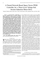
ⅷ Connection Diagrams
v FBL575AW, FBL575CW, v FBL575SW, FBL5120SW
FBL5120AW, FBL5120CW
●
Motor cable should be no more than 34.4 feet (10.5 m) in length. The motor comes with 20 inch (500 mm) long connector-equipped cable which can be extended by using an
accessory extension cable (sold separately).
●
There are six different length extension cables. Also there are flexible extension cables.
[Length: 3.3 ft. (1 m), 6.6 ft. (2 m), 9.8 ft. (3 m), 16.8 ft. (5 m), 23 ft. (7 m), 32.8 ft. (10 m)]
●
Extension Cables➝ Page B-44
●
Signal wires and motor wires should be kept away from equipment, power cables and other sources of magnetic noise.
20 inch ͑500 mm͒
POWER
ALARM
S.S.
MOTOR
S.D.
SPEED
INPUT
COM
1
2
3
4
EXT.VR.
CW
CCW
5
6
7
8
SLOW
DOWN
N.C.
L
10
11
H
M
9
3
2
1
20 kΩ 1/4 W
12
FG
L3
L2
L1
GND
SPEED
OUT
ALARM
OUT
Motor
Driver
Motor cable w/connector
Speed Potentiometer
Ground
Speed Signal Output
Alarm Signal Output
(included)
Three-phase
200-230 VACϮ10%
50/60 Hz
EXT INT.
CW Signal Input
CCW Signal Input
Protective Earth (P.E.)
Cross sectional area: AWG18 (0.75 mm
2
min.)
ϩ24V
Connection is not necessary
when using the driver's built-in
power supply.
Slow Down
Signal Input
Speed
Potentiometer
Selection Input
ON: External Potentiometer
OFF: Internal Potentiometer
͒ ͑
ON: CW Rotation
OFF: Stop
͑
͒
ON: CCW Rotation
OFF: Stop
͒ ͑
ON: Slow Down
OFF: Normal
͒ ͑
20 inch ͑500 mm͒
POWER
ALARM
S.S.
MOTOR
S.D.
SPEED
INPUT
COM
1
2
3
4
EXT.VR.
CW
CCW
5
6
7
8
SLOW
DOWN
N.C.
L
10
11
H
M
9
3
2
1
20 kΩ 1/4 W
12
FG
N.C
N
L
GND
SPEED
OUT
ALARM
OUT
Motor
Driver
Motor cable w/connector
Slow Down
Signal Input
Speed Potentiometer
Ground
Speed Signal Output
Alarm Signal Output
͑included͒
Single-phase
100-115 VACϮ10%
50/60 Hz
Single-phase
200-230 VACϮ10%
50/60 Hz
EXT INT.
ϩ24V
Connection is not necessary
when using the driver's built-in
power supply.
Speed
Potentiometer
Selection Input
ON: External Potentiometer
OFF: Internal Potentiometer
͒ ͑
ON: CW Rotation
OFF: Stop
͑
͒
ON: CCW Rotation
OFF: Stop
͒ ͑
ON: Slow Down
OFF: Normal
͒ ͑
CW Signal Input
CCW Signal Input
Protective Earth (P.E.)
Cross sectional area: AWG18 (0.75 mm
2
min.)
v Terminals
● Round Terminal with Insulation ● U-Shape Terminal with Insulation
0.24 inch (6.2 mm) max.
0.13 inch (3.2 mm) min.
0.35 inch (9 mm) min.
0.24 inch (6.2 mm) max.
0.13 inch min.
(3.2 mm)
0.35 inch (9 mm) min.
ⅷ Signal Input Timing Chart
CW
CCW
SLOW DOWN
EXT.VR.
CW
CW
CW
CW
CW
CW
CCW
Motor
Input Signal
Run/Speed-
Select/Stop
Run/
Brake
Change Direction/
Quick Reverse
Acceleration/
Deceleration
Brake
Signal
Input
ON
OFF
ON
OFF
ON
OFF
ON
OFF
●
All operations of run, stop, direction change, deceleration and instantaneous
stop can be controlled by the input signals of CW, CCW and SLOW DOWN.
●
If the CW input is set to ON, the motor rotates in a clockwise direction as viewed
from the shaft end of the motor; if the CW input is set to OFF, the motor stops. If
the CCW input is set to ON, the motor rotates in the counterclockwise direction
as viewed from the shaft end of the motor; if the CCW input is set to OFF, the
motor stops. If both of the CW and CCW input are set to ON, the motor rotates
in the clockwise direction. The acceleration time is set by the built-in
acceleration potentiometer (S.S.).
●
If the SLOW DOWN input is set to ON, the deceleration time is the value set by
the built-in deceleration potentiometer (S.D.); if this input is set to OFF, the
motor stops instantaneously.
●
If the EXT. VR. input is set to ON, the external speed potentiometer or external
DC voltage can be selected; if this input is set to OFF, the built-in speed
potentiometer is selected.
Notes:
●
Pay attention to the temperature rise of the motor when used in applications requiring short cycles or bi-directional operation.
●
Operate the motor so that the temperature of the motor case remains below 194°F (90°C) and the temperature of the driver remains below 176°F (80°C). If the temperature of the
heat sink in the driver exceeds 194°F (90°C), the overheat performing protection activates and stops the motor.
●
Precautions should be taken to ensure that while lowering the load or other operations in which the load exerts a rotational force on the motor shaft, the inverter's primary voltage
does not exceed permissible levels, which could damage the driver.
B-42
ORIENTAL MOTOR GENERAL CATALOG 2003/2004
Specifications B-36
Characteristics B-37
System Configuration B-35Features B-34
Specifications B-36
Characteristics B-37
System Configuration B-35Features B-34
Speed Control Systems
ⅷ Input Signal Circuit
v Input Circuit
Common to EXT.VR., CW, CCW, SLOW DOWN
INPUT COM
GND
4.8 kΩ
EXT.
INT.
I/O power supply switch (Front panel)
INPUT
Reinforced insulation
photocoupler
ⅷ Output Signal Circuit
v Output Circuit
Common to SPEED OUT and ALARM OUT
GND
External use
condition
26.4 VDC max.
10 mA max.
Driver
Internal circuit
Reinforced insulation
photocoupler
OUTPUT
v Connection Example for Input Signals
• Control by Small Capacity Relays
Flip the I/O power supply switch to "INT.".
Use a small capacity contact point type relay capable of switching 24 VDC, 0.5
mA.
Driver
EXT.VR.
CW
CCW
SLOW DOWN
ON
OFF
OFF
OFF
ON
ON
OFF: Internal
ON: External
OFF: Stop
ON: CW Rotation
OFF: Stop
ON: CCW Rotation
OFF
ON
OFF: Brake
ON: Slow down
GND
v Connection Example for Output Signals
ALARM OUT
SPEED OUT
GND
R
Driver User's controller
Vcc
• Control by Transistor Output Type PLC
Flip the I/O power supply switch to EXT. position (factory
setting).
ϩ 24 V
GND
EXT.VR.
CW
CCW
SLOW DOWN
DriverController
User's
Transistor
INPUT
GND
INPUT
COM
Note:
● Since the signal output is an "Open Collector" output, an external power supply
(Vcc) is necessary. For the external power supply, use 26.4 VDC or less and
connect a limit resistance (R) not exceeding 10 mA. This connection is not
necessary when the speed output or the alarm output functions are not used.
✽ To check the motor speed visually, connect a speed indicator SDM496
(sold separately). See page A-214 for more information.
Speed signal output:
Motor speed ϭ
Alarm signal output:
Output at a rate of 12 pulses per motor
rotation.
Output when the protection function for
overload, overheat, overvoltage, under voltage
or out-of-phase has been activated. When
output, the current flows between ALARM
OUT and GND terminal.
ϫ 60 [r/min]
Speed output cycle rate [Hz]
12
Precautions to observe when using a controller with an
internal clamp diode: When using a controller with an internal
clamp diode, be sure to set the I/O power supply switch on
the front panel to the EXT. (external DC power supply)
position. If the I/O power supply switch is in the INT. (built-in
power supply) position, the current will flow as indicated by
the arrows in the diagram, thereby causing the motor to run
abnormally.
Driver
INPUT
COM
INT.
EXT.
GND
INPUT
2.4 kΩ
Controller
Clamp
Diode
Transistor
ϩ24V
ORIENTAL MOTOR GENERAL CATALOG 2003/2004
B-43
Dimensions B-38
Connection and Operation B-40
Motor and Driver Combinations B-43
Dimensions B-38
Connection and Operation B-40
Motor and Driver Combinations B-43
Speed Control Systems
Brushless DC Motor Systems
DC Input
AC Motor Systems
BX
FBL2
AXU
AXH
BHF ES
US
Introduction
Before Using a
Speed Control
System
AC Input
ⅷ Method of Speed Setting
v Speed Control by Built-in Potentiometer
Motor speed is adjusted by using the built-in potentiometer located on the front panel. The built-in potentiometer is selected when
the EXT. VR. input has been set to OFF.
v Speed Control by External Potentiometer
To control the speed of the motor with an external
potentiometer, connect the external potentiometer provided
with the motor as follows. The EXT. VR. input should be set
to ON.
v Speed Control by External DC Voltage
To control the speed of the motor by DC voltage, connect the
DC power supply as follows. The EXT. VR input should be
set to ON.
Driver
I/O
6
7
8
9
H
M
L
10
11
12
GND
SPEED OUT
ALARM OUT
N.C.
External DC Power Supply
0ϳ5 VDC
1 mA min.
Ϫ
ϩ
Ϫ
ϩ
Signal Wire 3.3 feet (1 m)
Ϫprovided
Shielded Wire
Driver
I/O
6
7
8
9
Hቤ
Mባ
Lቢ
10
11
12
GND
SPEED OUT
ALARM OUT
N.C.
Signal Wire 3.3 feet (1 m)
- provided
Shielded Wire
High Speed
External Potentiometer
1
2
3
1
3
1000
2000
3000
012345
DC Voltage ͓VDC͔
Speed ͓r/min͔
DC voltageϪspeed characteristics
(Representative Values)
3000
2000
1000
020406080100
Speed ͓r/min͔
External speed potentiometer dial scaleϪspeed characteristics
(Representative Values)
Dial Plate Value
Notes:
● Signal wires provided should be used. (0.13 in. dia. 3.3 ft. length)
The shielded wire of the signal line should be connected to the GND terminal. Also ensure that the shielded wire does not come into contact with other terminals on the
external potentiometer or DC voltage source.
● Do not allow the voltage to exceed 5V, and be sure that there are no errors in polarity when making the connections.
Ⅵ List of Motor and Driver Combinations
Model name for motor, driver and gearhead combinations are shown below.
ⅷ Combination Type
● Enter the gear ratio in the box (Ⅺ) with the model name.
ⅷ Round Shaft Type
1/10
1/6
75
120
FBLM575W-A
FBLM5120W-A
FBL575AW-A
FBL575CW-A
FBL575SW-A
FBL5120AW-A
FBL5120CW-A
FBL5120SW-A
FBLD75AW
FBLD75CW
FBLD75SW
FBLD120AW
FBLD120CW
FBLD120SW
Driver ModelMotor ModelModel
Output Power
WHP
Driver ModelGearhead ModelMotor ModelModel
Output Power
HP W
1/10
GFB5GⅪ
FBLM575W-GFB
FBLM5120W-GFB
1/6
75
120
FBLD75AW
FBLD75CW
FBLD75SW
FBLD120AW
FBLD120CW
FBLD120SW
FBL575AW-Ⅺ
FBL575CW-Ⅺ
FBL575SW-Ⅺ
FBL5120AW-Ⅺ
FBL5120CW-Ⅺ
FBL5120SW-Ⅺ
B-44
ORIENTAL MOTOR GENERAL CATALOG 2003/2004
Specifications B-36
Characteristics B-37
System Configuration B-35Features B-34
Specifications B-36
Characteristics B-37
System Configuration B-35Features B-34
Speed Control Systems
Ⅵ Accessories
(Sold separately)
ⅷ Extension Cable
● Max. extended length: 34.5 feet (10.5 m)
● Max. extended length: 34.5 feet (10.5 m)
ⅷ Flexible Extension Cable
Model
CC01FBL
CC02FBL
CC03FBL
CC05FBL
CC07FBL
CC10FBL
Length: L [ft. (m)]
3.3 (1)
6.6 (2)
9.8 (3)
16.4 (5)
23.0 (7)
32.8 (10)
Motor Side
Driver Side
Housing
5557Ϫ12R (MOLEX)
L
Housing
5559Ϫ12P (MOLEX)
Model
CC01FBLR
CC02FBLR
CC03FBLR
CC05FBLR
CC07FBLR
CC10FBLR
Length: L [ft. (m)]
3.3 (1)
6.6 (2)
9.8 (3)
16.4 (5)
23.0 (7)
32.8 (10)
Motor Side
L
Driver Side
5559Ϫ12P (MOLEX)
Housing
5557Ϫ12R (MOLEX)
Housing
0.41 inch (
10.5 mm)
v
Precautions for use of the Flexible Extension Cables
(1) Do not bend the cable at the cable connector location.
OK
Avoide
(3) The motor cable itself is not designed to be bent. When
bending is necessary, be sure to bend at the flexible
extension cable.
Motor cable
(It must be fixed.)
Motor
Flexible extension cable
(Bendable)
Driver
(2)
Use the product with a minimum bend radius of 2.36 inch (60 mm).
Avoide
OK
ORIENTAL MOTOR GENERAL CATALOG 2003/2004
B-45
Dimensions B-38
Connection and Operation B-40
Motor and Driver Combinations B-43
Dimensions B-38
Connection and Operation B-40
Motor and Driver Combinations B-43
Speed Control Systems
Brushless DC Motor Systems
DC Input
AC Motor Systems
BX
FBL2
AXU
AXH
BHF ES
US
Introduction
Before Using a
Speed Control
System
AC Input