Bài giảng thiết kế bể bùn hoạt tính
Bạn đang xem bản rút gọn của tài liệu. Xem và tải ngay bản đầy đủ của tài liệu tại đây (582.93 KB, 71 trang )
Activated Sludge Process
Design
2
Information Checklist
1. Select the type of biological treatment process.
2. Conduct a material mass balance and determine expected
range of flows (minimum, average, and peak) and
loadings (COD, TSS, nutrients, etc.).
3. Determine biological kinetic coefficients (lab studies).
4. Develop a preliminary site plan, piping layout, and
location of collection boxes, return sludge pumps, etc.
5. Obtain design criteria.
6. Obtain effluent quality criteria (BOD
5
, TSS, TN and TP).
7. Develop data on settling characteristics of the biological
solids.
8. Obtain list of equipment manufacturers and provide
equipment selection guide.
3
Biological Reactor
Design Criteria
1. Design a BNR process with anaerobic, anoxic, and aerobic
reactor.
2. Anaerobic will receive influent and returned sludge from clarifier.
Anoxic will receive effluent from anaerobic and recycle from
aerobic.
3. The effluent will have BOD
5
/TSS/TN/NO
3
-
-N/NH
4
+
-N/TP of
10/10/10/8/1/1 mg/L or better, respectively.
4. Provide four independent process trains in parallel.
5. Anaerobic and anoxic must be deep, square and θ>1.5 hr.
6. Provide equipment for measuring raw wastewater flow, return
activated sludge, waste sludge, and air supply.
7. Blowers shall be capable of delivering max. air requirements
considering the largest single unit out of service.
8. Aeration equipment shall provide complete mixing of MLSS
and shall be capable of maintaining a min. of 2.0 mg/L DO.
4
Design Criteria - continued
9. Diffusers and piping shall be capable of delivering 150% of
the average air requirements.
10. The sludge pump and piping for RAS shall be designed to
provide capacity up to 150% of average design flow.
11. Internal recycle between aeration and anoxic basins will have
a capacity 200% of the average design flow.
12. All sidestreams from the sludge-handling facilities (thickeners,
digesters, and dewatering units) shall be returned to the
aeration basin.
13. The sludge wasting shall be achieved from the common
collection box containing the effluent MLSS from aeration
basins.
14. The basin hydraulics shall be checked at peak design flow plus
the design return sludge flow when only three basins are in
operation.
5
Design Criteria - continued
12. The biological kinetic coefficients and operational parameters
shall be determined from laboratory studies.
Sludge age, θ
c
= 12 days
Y= 0.6 mg VSS/mg BOD
5
; k
d
= 0.06 day
-1
Y
N
= 0.2 mg VSS/mg NH
4
+
-N; k
d,N
= 0.05 day
-1
(N=nitrification)
MLVSS = 3000 mg/L; MLVSS/MLSS = 0.8
RAS concentration = 10,000 mg TSS/L
BOD
5
= 0.68 BOD
L
Biological solids are 65% biodegradable.
13. Other conditions
Q
peak
= 1.321 m
3
/sec, Q
ave
= 0.44 m
3
/sec
BOD
5
, S
0
= 250 mg/L, Org-N= 17 mg/L, NH
4
+
-N= 19 mg/L,
NO
3
-
-N= 0 mg/L, TN= 36 mg/L, TP= 6 mg/L
TSS, X
0
= 260 mg/L; primary sludge VSS/TSS = 0.74
Anaerobic digester solids content = 0.06
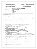
Schematic Flow and
Piping Arrangement
6
7
Design Strategy
1. Conduct a material mass balance
2. Calculate θ of anaerobic zone
3. Calculate θ
c
, biomass increase, and θ of anoxic zone
4. Calculate θ
c
, biomass increase, and θ of aerobic zone
5. Calculate the dimensions of anaerobic, anoxic, and
aerobic reactors
6. Design the required mixing equipment
7. Design aeration system
8. Select influent and effluent structure, develop
hydraulic profile
8
Design Calculations
First iteration
1. Calculate influent flow (stream 1)
Flow = 0.44 m
3
/sec × 86,400 sec/d = 38,016 m
3
/d
BOD
5
= 38,016 m
3
/d×250 g/m
3
×kg/1,000 g = 9,504 kg/d
TSS = 38,016 m
3
/d×260 g/m
3
×kg/1,000 g = 9,884 kg/d
Org-N= 646 kg/d, NH
4
+
-N= 722 kg/d,
NO
3
-
-N= 0 kg/d, TN= 1,369 kg/d, TP= 228 kg/d
2. Calculate primary sludge characteristics (stream 3)
BOD
5
(34% removal) = 9,504 kg/day × 0.34 = 3,231 kg/d
TSS (63% removal) = 9,884 kg/day × 0.63 = 6,227 kg/d
Org-N (30% removal)= 194 kg/d
NH
4
+
-N (0.36% removal)= 2.6 kg/d
NO
3
-
-N= 0 kg/d
TN (14.4% removal)= 197 kg/d
TP (16% removal)= 37 kg/d
Solids concentration = 4.5%
Specific gravity = 1.03
Sludge flow rate = 6,227 kg/d × 1,000 g/kg ÷ 0.045 g/g ÷1.03 ÷ 1 g/cm
3
÷
10
6
m
3
/m
3
= 134 m
3
/day
9
Design Calculations - continued
3. Calculate primary treated effluent (stream 4)
Q = 38,016 m
3
/d - 134 m
3
/d = 37,882 m
3
/d
BOD
5
= 9,504 kg/ - 3,231 kg/d = 6,273 kg/day
= 6,273 kg/d ÷ 37,822 m
3
/d × 1000 g/kg = 166 mg/L
TSS = 9,884 kg/d - 6,227 kg/d = 3,657 kg/day
= 3,657 kg/d ÷ 37,822 m
3
/d × 1000 g/kg = 97 mg/L
Org-N = 452 kg/d → 12 mg/L
NH
4
+
-N = 720 kg/d → 19 mg/L
NO
3
-
-N= 0 kg/d
TN = 1172 kg/d → 31 mg/L
TP = 192 kg/d → 5 mg/L
4. The characteristics of streams 2 and 5 are the same as those for
streams 1 and 4, respectively.
5. Effluent standards (stream 6) were given as design criteria
6. Calculate WAS (stream 7)
Eff. BOD
5
= Eff. sol. BOD
5
+ BOD
5
of eff. biological solids
Eff. sol. BOD
5
= 10 mg/L – 10 mg/L × 0.65 ×1.42 × 0.68 = 3.7 mg/L
10
Design Calculations - continued
Increase in TVSS due to overall BOD
5
removal = Y/(1+k
d
·θ
c
) (S
0
- S
1
) Q
= 0.6/(1+0.06×12) (166 – 3.7) g/m
3
× 37,882 m
3
/d× kg/1000 g
= 2,144 kg/d
Increase in TVSS due to nitrification = Y
N
/(1+k
d
,
N
·θ
c
) (S
0,N
- S
1,N
) Q
= 0.2/(1+0.05×12) (19* – 1**) g/m
3
× 37,882 m
3
/d× kg/1000 g
= 85 kg/d
*NH
4
+
-N in stream 4
**Design criteria
Increase in TSS = (2,144+85) kg/d ÷ 0.8 = 2,789 kg/d
TSS in WAS = Increase in TSS - TSS lost in the effluent
= 2,789 kg/d - [10 g/m
3
× (37,882 - Q
WAS
***) m
3
/d ×kg/1000 g]
= 2,410 kg/d
MLSS concentration = 3,000 mg/L ÷ 0.8 = 3,750 mg/L
Q
WAS
= 2,410 kg/d ÷ 3,750 mg/L × 10
6
kg/mg × 10
-3
L/m
3
= 643 m
3
/d
***first iteration assumes that Q
WAS
=0
BOD
5
in WAS =2,410 kg/d × 0.65 g/g × 1.42 g/g × 0.68 g/g = 1,513 kg/d
Sol. BOD
5
= 3.7 g/m
3
× 643 m
3
/d × kg/1000 g = 2.4 kg/d
Total BOD
5
in WAS = 1,513 kg/d + 2.4 kg/d = 1,515 kg/d
11
Design Calculations - continued
Compute Org-N, NH
4
+
-N, NO
3
-
-N, TN in WAS
Org-N = 0.122* kg Org-N/kg TVSS ×2,410 kg TSS/d × 0.8= 235 kg/d
NH
4
+
-N = 1** g NH
4
+
-N/m³ × 643 m³/d × 10
-3
kg/g= 0.64 kg/d
NO
3
-
-N = 8** g NO
3
-
-N /m³ × 643 m³/d × 10
-3
kg/g= 5.1 kg/d
TN = 235+0.64+5.1= 241 kg/d
* Based on chemical formula C
60
H
87
O
23
N
12
P
** Design criteria
Compute TP in WAS
TP = TP in influent – TP in effluent
= 192*** kg/d – 1 mg P/L × 37,882 m
3
/d× kg/1000 g = 154 kg/d
*** From stream 4
7. Q
r
into anaerobic zone (mass balance)
10,000 g/m³ × Q
r
m³/d = 3,750 g/m³ × (Q+Q
r
) m³/d
Q
r
= 22,729 m³/d
Q
r
/Q = 22,729 ÷ 37,882 = 0.6
8. Q
recycle
into anoxic zone
Total NO
3
-
-N lost by denitrification = TN influent (stream 4) - TN effluent - TN
WAS
= 1172 – 379 – 241 = 552 kg/d
12
552 kg/d = (22,729 m³/d + Q
recycle
m³/d )× 8 g NO
3
-
-N /m³ × 10
-3
kg/g
Q
recycle
= 46,271 m³/d
Q
recycle
/Q= 46,271 ÷ 37,882 = 1.22 ≈ 1.25
9. This design considers a stripping of P from WAS (stream 8). In order to
reduce the P buildup in the BNR system, PO
4
3-
ions are released under anaerobic
condition, thus alum precipitation of PO
4
-P as AlPO
4
and denitrification of
NO
3
-
-N in WAS are achieved. A summary of how this process affect the whole
process performance is shown below:
.
Design
Calculati
ons -
continued
Stream Flow
m³/d
BOD
5
kg/d
TSS
kg/d
Org N
kg/d
NH
4
+
-N
kg/d
NO
3
-
-N
kg/d
TN
kg/d
TP
kg/d
7 643 1515 2410 235 0.6 5.1 241 154
8 648 1515 2921 235 0.6 0 236 154
Increase in flow rate is caused by addition of alum, increase in TSS is
caused by precipitation of AlPO
4
and Al(OH)
3
, biodegradable fraction =
0.54, organic fraction = 0.66. This example only considers the first iteration
13
10. Calculate combined sludge (stream 3 + stream 8)
Q = 134 m
3
/d + 648 m
3
/d = 782 m
3
/d
BOD
5
= 3,231 kg/d + 1,515 kg/day = 4,746 kg/d
TSS = 6,227 kg/d + 2,921 kg/d = 9,148 kg/d
11. PS and WAS are mixed and blended. Dilution water is needed to maintain
hydraulic loading in the thickener (9.8 m³/m²-d). Final effluent is used as
dilution water. It is assumed a solid loading of 46.9 kg/m²-d
Thickener area= 9,148 kg/d ÷ 46.9 kg/m²-d = 195 m²
Flow to the thickener= 9.8 m³/m²d × 195 m²= 1911 m³/d
Flow of dilution water= 1,911 – 782 = 1,129 m³/d
12. Characteristics of blended sludge (stream 9)
BOD
5
and TSS in dilution water = 379 kg/d×1,129 m³/d÷37,882 m³/d = 11 kg/d
BOD
5
in stream 9 = 3,231 + 1,515 + 11 = 4,757 kg/d
TSS in stream 9 = 9,148+11 = 9,159 kg/d
Biodegradable fraction of TSS = 4,757 kg/d ÷ (9,159 kg/d×1.42 ×0.68) = 0.54
TVSS/TSS= (0.74 × 6,227
(stream 3)
+0.66 × 2,921
(stream 8)
+ 0.8×11) ÷ 9,159 = 0.72
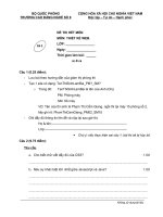
Design
Calculati
ons -
continued
#5 #6 #5
14
10. Calculate combined sludge (stream 3 + stream 8)
Q = 134 m
3
/d + 648 m
3
/d = 782 m
3
/d
BOD
5
= 3,231 kg/d + 1,515 kg/d = 4,746 kg/d
TSS = 6,227 kg/d + 2,921 kg/d = 9,148 kg/d
11. PS and WAS are mixed and blended. Dilution water is needed to maintain
hydraulic loading in the thickener (9.8 m³/m²-d). Final effluent is used as
dilution water. It is assumed a solid loading of 46.9 kg/m²∙d
Thickener area= 9,148 kg/d ÷ 46.9 kg/m²∙d = 195 m²
Flow to the thickener= 9.8 m³/m²∙ d × 195 m²= 1911 m³/d
Flow of dilution water= 1,911 m
3
/d – 782 m
3
/d = 1,129 m³/d
12. Characteristics of blended sludge (stream 9)
BOD
5
and TSS in dilution water = 10 mg/L × 1,129 m³/d = 11 kg/d
BOD
5
in stream 9 = 3,231 + 1,515 + 11 = 4,757 kg/d
TSS in stream 9 = 9,148 + 11 = 9,159 kg/d
Biodegradable fraction of TSS = 4,757 kg/d ÷ (9,159 kg/d×1.42×0.68) = 0.54
TVSS/TSS= (0.74 × 6,227
(stream 3)
+0.66 × 2,921
(stream 8)
+ 0.8×11) ÷ 9,159 = 0.72
Design
Calculati
ons -
continued
#5 #6 #5
Schematic Flow and
Piping Arrangement
15
16
13. Calculate thickened sludge (stream 10)
TSS = 0.85
(efficiency)
× 9,159 kg/day = 7,785 kg/day
Q = 7,785 kg/d × 1,000 g/kg ÷ 0.06 g/g ÷ 1.03 ÷ 1 g/mL÷ 10
6
mL/m
3
= 126 m
3
/d
BOD
5
= 4,757 kg/d × 0.85 = 4,043 kg/d
Org N = (194
(stream 3)
+ 235
(stream 8)
) × 0.85 = 366 kg/d
NH
4
+
-N = (2.6
(stream 8)
+ 0.6
(stream 8)
+ 1.1
(dilution water)
kg/d) × 126 m³/d ÷
1,911 m³/d = 0.3 kg/d
NO
3
-
-N = 0 kg/d (complete denitrification)
TN = 366 (Slide #16) + 0 + 0.3= 366 kg/d
TP = 82
(non-AlPO4(s))
kg/d× 0.85 (70 kg/d) + 110
(AlPO4(s))
kg/d × 1
(100% efficiency)
=
180 kg/d
14. Stream 11 is calculated with respect to both streams 9 and 10
Design
Calculations -
continued
17
15. Characteristics of anaerobically digested sludge (stream 12 and
supernatant)
BOD
5
and TS in the supernatant = 3,000 and 4,000 mg/L, respectively; TS
in digested sludge = 5%; TVS reduced = 52%; BOD
5
stabilization = 60%,
Org N into to NH
4
+
-N = 15%, Org N into to soluble Org N = 10%, gas
production = 0.936 m
3
/kg TVS reduced (= 15 ft
3
/lb TVS)
TVSS
(stream 10)
=7,785 kg/d × 0.72
(TVSS/TSS stream 9)
= 5,605 kg/d
TVSS
(stabilized)
= 5,065 kg/d × 0.52= 2,915 kg/d
TVSS
(remaining)
= 5,605 – 2,915= 2,690 kg/d
TSS
(remaining)
= 7,785 kg/d – 2,915 kg/d= 4,870 kg/d
Q
(stream 10)
= Q
(stream 12)
+ Q
(supernatant)
126 m³/d = TSS
(stream 12)
÷ (0.05 × 1,030) + TSS
(supernatant)
÷ (0.004 × 1,000)
TSS
(supernatant)
= 4,870 kg/d - TSS
(stream 12)
Solving for TSS
(supernatant)
and TSS
(stream 12)
Design
Calculati
ons -
continued
18
TSS
(supernatant)
= 136 kg/d
TSS
(stream 12)
= 4,734 kg/d
Q
(supernatant)
= 34 m³/d
Q
(stream 12)
= 92 m³/d
Others components in stream 12
BOD
5
= 4,043
(stream 10)
kg/d × (1-0.6) – 3000 g/m³ × 34 m³/d ×10
-3
kg/g
= 1,515 kg/d
Org N = 366
(stream 10)
× (1- 0.1- 0.15) × (4,734 kg/d ÷ 4,870 kg/d) + 366 kg/d × 0.1×
(92 m³/d ÷ 126 m³/d) = 294 kg/d
NH
4
+
-N = 366 kg/d × 0.15 + 0.3
(stream 10)
kg/d × (92 m³/d÷ 126 m³/d) = 40 kg/d
NO
3
-
-N = 0 kg/d (complete denitrification)
TN = 294 + 40 + 0 = 334 kg/d
TP = 70 kg/d × (1-0.3) × (4,734 kg/d ÷ 4,870 kg/d) + 366 kg/d × 0.1 × (92
m³/d÷126 m³/d)= 63 kg/d
TP = 63
(non-AlPO
4
(s))
kg/d + 110
(AlPO
4
(s))
kg/d= 173 kg/d
Biodegradable fraction of TSS = 1,515 kg/d ÷ (4,734 kg/d×1.42×0.68)= 0.33
TVSS/TSS = 2,690 ÷ 4,870 = 0.55
Design
Calculati
ons -
continued
19
Design Calculations - continued
Others components in supernatant
BOD
5
= 3000g/m³ × 34 m³/d ×10
-3
kg/g = 102 kg/d
Org N = 366
(stream 10)
× (1- 0.1- 0.15)×(136 kg/d÷4,870 kg/d) + 366 kg/d × 0.1×
(34 m³/d÷126 m³/d)= 18 kg/d
NH
4
+
-N =366 kg/d × 0.15 + 0.3
(stream 10)
kg/d × (34 m³/d÷126 m³/d)= 15 kg/d
NO
3
-
-N = 0 kg/d (complete denitrification)
TN = 18 + 15 + 0 = 33 kg/d
TP = 7
(non-AlPO4(s))
kg/d
Gas produced = 0.936 m
3
/kg × 2,915 kg/d = 2,728 kg/d
16.Characteristics of dewatered sludge
The sludge dewatering facility consists of filter presses. It is assumed that
the sludge cake has 25% solids; dewatering facility captures 95% solids;
specific gravity of sludge cake is 1.06; organic polymers added to the sludge
for conditioning are 0.5% of sludge solids; and 80% added chemicals are
incorporated into the sludge cake. Total volume of belt wash water and
chemical dilution water = 35 L/kg TSS. No BOD
5
is added by chemical
conditioning.
20
Design Calculations - continued
Flow rate of belt wash and chem. dilution water = 4,734 kg/d × 35 L/kg ×
10
-3
m³/L = 166 m³/d
Others constituents in belt wash and chem. dilution water
BOD
5
= (379
(plant effluent)
kg/d ÷ 37,882 m³/d)× 166 m³/d = 1.7 kg/d
TSS = (379
(plant effluent)
kg/d ÷ 37,882 m³/d)× 166 m³/d = 1.7 kg/d
Org N = (38
(plant effluent)
kg/d ÷ 37,882 m³/d)× 166 m³/d = 0.2 kg/d
NH
4
+
-N = 0.2 kg/d
NO
3
-
-N = 1.3 kg/d
TN = 1.3 + 0.2 + 0.2 = 1.7 kg/d
TP = 0.2 kg/d
TSS removed = 4,734 kg/d × 0.95 = 4,497 kg/d
Organic polymer removed = 4,734 kg/d × 0.005 × 0.8 = 19 kg/d
Total TSS = 4,497 + 19 = 4,516 kg/d
Q sludge cake = 4,516 ÷ (0.25 × 1,060) = 17 m³/d
21
Others constituents in the sludge cake
BOD
5
= 1,515 kg/d × 0.95= 1,439 kg/d
Org N = 294 kg/d × 0.95= 279 kg/d
NH
4
+
-N = 40 kg/d × (17 m³/d÷92 m³/d)= 7.4 kg/d
NO
3
-
-N = 0 kg/d (complete denitrification)
TN = 279 + 7.4 + 0 = 286 kg/d
TP = 170 kg/d
Q filtrate = 92 m³/d + 166 m³/d - 17 m³/d = 241 m³/d
TSS in filtrate = 4,734 kg/d + 1.7 kg/d + 4,734 kg/d × 0.005×(1-0.8)
– 4,497 kg/d u= 243 kg/d
Total Q stream 16 = 1,785 m³/d + 34 m³/d + 241 m³/d= 2,060 m³/d
Total TSS stream 16 = 1,374 kg/d + 136 kg/d + 243 kg/d= 1,753 kg/d
Design
Calculati
ons -
continued
22
Design Calculations - continued
Final results
The previous computational procedure must be repeated for
several iteration to obtain a stable value of influent quality
(< 1% of fluctuation.)
The effluent quantity discharged from the plant will be slightly
less than the influent flow due to evaporation loss, loss of water in
production of digester gases, and moisture contained in the sludge
cake.
Next slide shows the characteristic of streams in final iteration of
material mass balance analysis
Stream Flow
m³/d
BOD
5
kg/d
TSS
kg/d
Org N
kg/d
NH
4
+
-N
kg/d
NO
3
-
-N
kg/d
TN
kg/d
TP
kg/d
1 38016 9504 9884 646 722 0 1369 228
2 38016 9504 9884 646 722 0 1369 228
3 134 3231 6227 194 2.6 0 197 37
4 37882 6273 3657 452 720 0 1172 192
5 40050 7210 5498 558 776 0 1333 216
6 39303 393 393 39 39 314 393 39
7 747 1760 2800 273 0.8 6.0 280 176
8 752 1760 3385 273 0.8 0 274 176
9 2011 5003 9623 468 4.4 0 482 214
10 132 4253 8180 398 0.3 0 398 201
11 1878 750 1444 70 4.1 0 74 13
12 97 1596 5008 320 44 0 364 193
13 35 105 140 19 16 0 35 7.4
14 18 1516 4778 304 8.2 0 312 190
23
Stream Flow
m³/d
BOD
5
kg/d
TSS
kg/d
Org N
kg/d
NH
4
+
-N
kg/d
NO
3
-
-N
kg/d
TN
kg/d
TP
kg/d
15 255 82 257 16 36 0 52 3.6
16 2168 937 1841 105 56 0 161 24
The influent to the BNR (stream 5) is characterized as:
BOD
5
= 180 mg/L
Org N = 13.9 mg/L
NH
4
+
-N = 19.5 mg/L
NO
3
-
-N = 0 mg/L
TN = 33.4 mg/L
TP = 5.4 mg/L
TSS = 137 mg/L
Q = 40,050 m³/d
Applying 5~10% as safety factor for the design of BNR
BOD
5
= 200 mg/L
Org N= 15 mg/L
NH
4
+
-N= 20 mg/L
NO
3
-
-N= 0 mg/L
TN= 35 mg/L
TP= 6 mg/L
TSS= 150 mg/L
Q = 42,000 m³/d
24
25
Design Calculations - continued
Dimensions of Anaerobic Zone
1. A minimum θ (HRT) of 1.5 h for anaerobic zone is generally used for
typical municipal wastewater.
V
anaerobic
= 1.5 h × 42,000 m³/d ÷ 24 h/d= 2,625 m³
Dimensions of Anoxic Zone
1. Calculate design θ
c
(SRT) for denitrification
max. specific growth under field condition (µ’
max
) = max. specific growth
rate (µ
max,DN
) × temp. correction (F
T
) × DO correction (F
DO
)
Typical values:
µ
max,DN
= 0.3 d
-1
F
T,DN
= 1.08
(T-20)
(T=15ºC)
F
DO,DN
= (1-DO
max
) (DO
max
=0.10 mg/L)
µ’
max,DN
= 0.184 d
-1