surveillance in a smart home environment
Bạn đang xem bản rút gọn của tài liệu. Xem và tải ngay bản đầy đủ của tài liệu tại đây (601.05 KB, 53 trang )
Surveillance in a Smart Home
Environment
A thesis submitted in partial fulfilment
of the requirements for the degree of
Master of Science
By
RYAN STEWART PATRICK
B.S., The College of New Jersey, 2008
2010
Wright State University
WRIGHT STATE UNIVERSITY
SCHOOL OF GRADUATE STUDIES
June 9, 2010
I HEREBY RECOMMEND THAT THE THESIS PREPARED UNDER MY SUPERVISION
BY Ryan Patrick ENTITLED Surveillance in a Smart Home Environment BE ACCEPTED
IN PARTIAL FULFILLMENT OF THE REQUIREMENTS FOR THE DEGREE OF
Master of Science
.
Nikolao s Bourbak is, Ph. D.
Thesis Director
Thomas Sudkamp, Ph. D.
Department Chair
Committee on
Final Examination
Nikolao s Bourbakis, Ph. D.
Soon Chung, Ph. D.
Yong Pei, Ph. D.
John A. Bantle, Ph.D.
Interim Dean, School of Graduate Studies
ABSTRACT
Patrick, Ryan. M.S. Department of Computer Science and Engineering, Wright State University,
2010. Surveillance in a Smart Home Environment.
A system for assisting the elderly in maintaining independent living is currently being designed.
When mature, it is exp ected that this system will have the ability to track objects that a resident may
lose periodically, detect falls within the home, and alert family members or health care professionals
to abnormal behaviors.
This thesis addresses the early s tages of this system’s development. It presents a survey of the
work that ha s previously been completed in the area of surveillance within a home environment,
information on the physical characteristics of the system that is being designed, early results re lated
to this system, and guidance on the future work that will have to be completed.
iii
Contents
1 Survey 1
1.1 Object Tracking in Smart Homes . . . . . . . . . . . . . . . . . . . . . . . . . . . . . 3
1.2 Methodology . . . . . . . . . . . . . . . . . . . . . . . . . . . . . . . . . . . . . . . . 3
1.3 Survey Elements . . . . . . . . . . . . . . . . . . . . . . . . . . . . . . . . . . . . . . 4
1.4 Discussion of Similar Systems . . . . . . . . . . . . . . . . . . . . . . . . . . . . . . . 6
1.5 Discussion of Generic Systems . . . . . . . . . . . . . . . . . . . . . . . . . . . . . . . 7
1.6 Conclusions . . . . . . . . . . . . . . . . . . . . . . . . . . . . . . . . . . . . . . . . . 9
2 Systems 10
2.1 Our System . . . . . . . . . . . . . . . . . . . . . . . . . . . . . . . . . . . . . . . . . 10
2.1.1 Our Hardware . . . . . . . . . . . . . . . . . . . . . . . . . . . . . . . . . . . 10
2.1.1.1 Image Acquisition . . . . . . . . . . . . . . . . . . . . . . . . . . . . 11
2.1.1.2 Synchroniza tion . . . . . . . . . . . . . . . . . . . . . . . . . . . . . 13
2.1.1.3 Image Quality . . . . . . . . . . . . . . . . . . . . . . . . . . . . . . 13
2.1.2 Background/Foreground Segmentation . . . . . . . . . . . . . . . . . . . . . . 13
2.1.2.1 Incompleteness . . . . . . . . . . . . . . . . . . . . . . . . . . . . . . 14
2.1.2.2 Background Over Time . . . . . . . . . . . . . . . . . . . . . . . . . 15
2.2 ICDSC Smart Homes Data Set . . . . . . . . . . . . . . . . . . . . . . . . . . . . . . 15
2.2.1 Image Quality . . . . . . . . . . . . . . . . . . . . . . . . . . . . . . . . . . . 15
2.2.2 Background/Foreground Segmentation . . . . . . . . . . . . . . . . . . . . . . 18
2.3 The TUM Kitchen Data Set . . . . . . . . . . . . . . . . . . . . . . . . . . . . . . . . 20
2.3.1 Background/Foreground Segmentation . . . . . . . . . . . . . . . . . . . . . . 21
3 Object Tracking 26
3.1 CAMShift Tracking of the Cutting Board . . . . . . . . . . . . . . . . . . . . . . . . 26
3.2 Template Matching Tracking of the Cutting Board . . . . . . . . . . . . . . . . . . . 26
iv
3.3 SURF Point Correlation . . . . . . . . . . . . . . . . . . . . . . . . . . . . . . . . . . 28
3.4 Good Features to Track . . . . . . . . . . . . . . . . . . . . . . . . . . . . . . . . . . 30
3.5 Indirect CAMShift Tracking . . . . . . . . . . . . . . . . . . . . . . . . . . . . . . . . 30
3.6 CAMShift in a Different Color space . . . . . . . . . . . . . . . . . . . . . . . . . . . 33
3.7 Kalman Filter . . . . . . . . . . . . . . . . . . . . . . . . . . . . . . . . . . . . . . . . 34
3.8 Particle Filter . . . . . . . . . . . . . . . . . . . . . . . . . . . . . . . . . . . . . . . . 35
3.9 Conclusions . . . . . . . . . . . . . . . . . . . . . . . . . . . . . . . . . . . . . . . . . 35
4 Future Work 38
4.1 Data Proces sing . . . . . . . . . . . . . . . . . . . . . . . . . . . . . . . . . . . . . . 38
4.2 Information from Multiple Cameras . . . . . . . . . . . . . . . . . . . . . . . . . . . 41
4.3 Sudden Lighting Changes . . . . . . . . . . . . . . . . . . . . . . . . . . . . . . . . . 41
References 42
v
List of Figures
1.1 Views from the ICDSC Smart Homes Data Set . . . . . . . . . . . . . . . . . . . . . 2
1.2 System Elements . . . . . . . . . . . . . . . . . . . . . . . . . . . . . . . . . . . . . . 4
2.1 Shadow in the Foreground . . . . . . . . . . . . . . . . . . . . . . . . . . . . . . . . . 14
2.2 Frame from ICDSC 2009 Smart Homes Data Set . . . . . . . . . . . . . . . . . . . . 16
2.3 Effects of Motion Blur . . . . . . . . . . . . . . . . . . . . . . . . . . . . . . . . . . . 17
2.4 Mug in the “Background” . . . . . . . . . . . . . . . . . . . . . . . . . . . . . . . . . 18
2.5 Magazine in the “Background” . . . . . . . . . . . . . . . . . . . . . . . . . . . . . . 19
2.6 Views from the TUM Kitchen Data Set . . . . . . . . . . . . . . . . . . . . . . . . . 20
2.7 Creation of a Background Image . . . . . . . . . . . . . . . . . . . . . . . . . . . . . 22
2.8 CAMShift Tracking Board . . . . . . . . . . . . . . . . . . . . . . . . . . . . . . . . . 23
2.9 CAMShift Tracking Cabinet . . . . . . . . . . . . . . . . . . . . . . . . . . . . . . . . 24
2.10 CAMShift Tracking Background . . . . . . . . . . . . . . . . . . . . . . . . . . . . . 25
3.1 CAMShift Tracking with Changing Scale . . . . . . . . . . . . . . . . . . . . . . . . . 27
3.2 Incorrect Template Matching . . . . . . . . . . . . . . . . . . . . . . . . . . . . . . . 28
3.3 Template Matching Based on All Views . . . . . . . . . . . . . . . . . . . . . . . . . 29
3.4 Segmentation of Skin and Cutting Board . . . . . . . . . . . . . . . . . . . . . . . . . 31
3.5 Determination of the Arms . . . . . . . . . . . . . . . . . . . . . . . . . . . . . . . . 32
3.6 Value - Saturation - Hue Image of Foreground . . . . . . . . . . . . . . . . . . . . . . 33
3.7 Particle Filter Tracking Pick-up . . . . . . . . . . . . . . . . . . . . . . . . . . . . . . 36
3.8 Particle Filter Tracking Movement . . . . . . . . . . . . . . . . . . . . . . . . . . . . 37
4.1 Video Frame . . . . . . . . . . . . . . . . . . . . . . . . . . . . . . . . . . . . . . . . 39
4.2 Same Frame after Foreground Segmentation . . . . . . . . . . . . . . . . . . . . . . . 40
vi
List of Tables
1.1 Element Importance . . . . . . . . . . . . . . . . . . . . . . . . . . . . . . . . . . . . 5
1.2 Object Locators . . . . . . . . . . . . . . . . . . . . . . . . . . . . . . . . . . . . . . . 6
1.3 Evaluation of Object Locator s . . . . . . . . . . . . . . . . . . . . . . . . . . . . . . . 6
1.4 Generic Tracking Systems . . . . . . . . . . . . . . . . . . . . . . . . . . . . . . . . . 7
1.5 Evaluation of Generic Tracking Systems . . . . . . . . . . . . . . . . . . . . . . . . . 8
2.1 Single Linksys Camera Transmission Rates . . . . . . . . . . . . . . . . . . . . . . . 12
3.1 Kalman Transition Matrix . . . . . . . . . . . . . . . . . . . . . . . . . . . . . . . . . 34
vii
ACKNOWLEDGEMENTS
I would like to acknowledge the many peo ple whose previous work and current assistance contributed
to this thesis. Whenever I hit a dead end and had no idea which direction to go next, Dr. Nikolaos
Bourbakis was there to make suggestio ns. When I was completely stumped by the inner workings
of Logitech’s WiLife camera system, Alexandros Pantelopoulos was able to lend his experience in
electrical engineering to help me understand the system’s operation. I would like to thank Alexandros
Karargyris for his suggestions on how improve the image acquisition and processing that was required
for this thesis. I would also like to express my gratitude to Brian Jackson for his suggestions on
tracking objects more reliably.
I would like to also thank the people who provided general support for my thesis. Without the
assistance of Donetta Bantle, navigating the bureaucracy of graduate school would have been much
more difficult; without the camaraderie of Rob Keefer, Athanasios Tsitsoulis, Mike Mills, Victor
Agbugba, Dimitrios Dakopoulos, Allan Rwabutaza, and Giuliano Manno , the ho urs spent in the lab
would have been more monotonous; without the technical support of Matt Kijowski, the setup of our
network of cameras would have b e e n much more frustrating; and without the support of the other
Computer Science and Engineering faculty, staff, and, especially, teaching assistants who helped me
adjust to life at Wright State.
I would es pecially like to thank my family. For two years, they put up with me living far from
home and starting conversations about my r e search with, “I tried something different, and thought I
fixed the problem, but ”. Without their unconditional support, the completion of this thesis would
not have been possible.
viii
1
Survey
As pa rt of this work, we evaluated similar sy stems tha t were designed in the last decade. We also
evaluated systems that were related to our area of work. That survey [Patrick and Bourbakis 2009]
is reproduced here.
In the last 10 years, resear ch in the field of automated multiple camera surveillance has grown
dramatically. [Stuart et al. 1999] beg an to experiment with methods for tracking objects within the
view of a camera and transferring infor mation about tra cked objects from one camera to another.
While [Stuart et al. 1999] only provided re sults on a simulation of a scene that was monitored by
several, non-overlapping cameras, several ideas, such as the notion of object “trajectories”, came
out of this work.
While the initial contributions of [Stuart et al. 1999] specifically addressed methods for the
surveillance of traffic in outdoor environments, interest in the auto mation of surveillance in indoor
environments grew from the prevalence of existing surveillance systems in public and private build-
ings. Indoor surveillance posed new challenges, and provided new benefits that were not present
in outdoor surveillance. Indoo r environments are ge nerally protected from fa c tors, such as wind
and water, that outdoor surveillance equipment would need to be robust to. However, the sudden
illumination changes that ar e not present in an outdoor environment, must be adequately dealt with
indoors.
A specialization of the indoor surveillance problem is the problem of surveillance in smart homes
and smar t rooms. While general surveillance systems attempt to use each camera to monitor a
broad area, thus limiting the number of required cameras, the goal of s urveillance in smart homes
and rooms is to efficiently capture details tha t may be important to the user. [Chen et al. 2008] and
[Aghajan 2009] illustrate this point well. In [Chen et al. 2008], five cameras ar e used to monitor two
hallways and one room. Only one pair of camera s has overlapping views, and that overlap is only
provided by an open door that is not guaranteed to be persistently open.
1
2
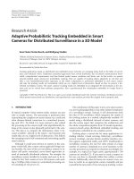
Alternatively, [Aghajan 2009] monitors one hallway and two rooms with a total of eight cameras.
Beyond the numerical difference, the systems in [Chen et al. 2008] and [Aghajan 2009], and envi-
ronments they monitor, are very different. [Chen et al. 2008] appears to use a system of cameras
that are mounted to the ceiling and, therefore, are located parallel to the ground. The ground plane
dominates the view that each camera has and each s c e ne is generally illuminated by artificial light.
Conversely, the scene and system in [Aghajan 2009] does not appear to be as predictable. While
many of the cameras appear to be mounted on the wall or ceiling and have a view of the scene that
is similar to the cameras in [Chen et al. 2008], camera 5 appears to be positioned a t an oblique
angle. The scene also appears to be lit by a c ombination of natural and artificial light. To further
complicate matters, both the natural and artificial light appea r to be intense enough to cause parts
of the scene to be washed out. In addition all of the other differences, very few of the cameras
in [Ag hajan 2009] have an adequate view of the ground plane. Many other planes (tables, chairs,
counter tops, cabinets, and a sofa) are visible, but many of the cameras have their view of ground
largely occluded. The eight camera views from [Aghajan 2009] are shown in Figure 1.1.
Figure 1.1: Views from the ICDSC Smart Homes Data Set
1.1. OBJECT TRACKING IN SMART HOMES 3
1.1 Object Tracking in Smart Homes
We focused our survey on video surveillance in smart homes around the central problem of monitoring
the location of items that an occupant may forget the location of. While this problem has been
worked on through the use of radio frequency identification (RFID) tags [Kidd et al. 1999], we
looked primarily a t systems that used vision to track items within a home. Due to the limited
number of systems that satisfy that narrow requirement, we also looked at systems that could be
extended to provide a more complete solution to this problem. That broader sc ope went on to
include systems that used a single camera to locate objects within a smart room and systems that
used multiple camera s to provide general indoor surveillance.
1.2 Methodology
We assigned values based on how much systems deviated from the ideal for each element. In the
cost element, more sophisticated hardware (PTZ cameras, stereo cameras, etc.) negatively affected
a system’s value. Likewise, systems whose expense incre ased be c ause of large storage or processing
requirements rec e ived lower values for cost. Friendliness was determined by the interface and images
that were presented to the user. Presentations that highlighted impo rtant information simply were
assigned higher values. Values for the range element were based on how much of a scene a system
was designed to cover. Systems that were confined to areas within rooms were assigned lower
values in that catego ry than systems that provided a view of a wide area. Calibration values were
assigned based on how easily a system could b e made ope rational. Systems that required the intricate
calibration of cameras or other hardware received lower values. System complexity had some relation
to system cost. More expensive systems gener ally had more sophisticated hardware. Systems that
required computational power that would be considered extraordinary to the average consumer were
assigned values tha t were lower than systems that could be run on hardware that a consumer can be
exp ected to already posse ss. Systems that could continue to work through physical problems that a
home environment may present, such as jostling, received higher values for the robustness element.
Systems that could be more easily reconfigured after the addition or subtractio n of cameras received
higher values for their scalability. Systems whose performance did not deteriorate over time, under
exp ected circumstances, had greater values in the lifetime category. The realtime value was arrived
at by how quickly a system would be expected to res pond to a request. A system that would need
certain conditions to be met first would not have a s high a value in that category as a system
that could respond immediately. Reliability was affected by how well the software could respond to
changes in the physical scene or the hardware. The number that was assigned for synthesis reflected
1.3. SURVEY ELEMENTS 4
how well a system joined information from multiple views. Thre e dimensional r e presentations would
receive higher values than two dimensional representations, and two dimensional representations
would receive higher values than systems with no synthesized representation.
1.3 Survey Elements
First, we proposed a number of elements that users, engineers, and software developers would be
concerned with in the production, deployment, and use of a surveillance system for a smart home.
Figure 1.2 defines each of the elements that were used in the evaluation and an example of how a
system would be ideal with respect to each element.
Figure 1.2: System Elements
Each element’s importance to a specific group that would interact with the system was assigned
1.3. SURVEY ELEMENTS 5
a number between 1 and 10. An assignment of 1 would indicate that the particular group did not
see the element as important in any way and an assignment of 10 would indicate that a particular
group saw the element as being of the utmost importance to them. Because a s urveillance system
in a smart home could potentially be used to monitor the well-being of an occupant and report
changes in their condition to a health care provider, each element was also assigned a value for how
impo rtant doctors and health care providers felt that element was to them. The averag e element
impo rtance was used to compare the r e lative impo rtance of ce rtain elements to others and to find
elements that had universal importance.
Element User Engineer Software Developer Doctor / Healthcare Professional Average
E1 10 8 7 2 6.75
E2 10 8 8 10 9
E3 10 10 5 8 8.25
E4 5 10 1 5 5.25
E5 7 10 6 8 7.75
E6 4 9 10 7 7.5
E7 10 10 10 10 10
E8 10 10 10 10 10
E9 10 9 7 10 9
E10 10 9 9 10 9.5
E11 10 10 10 10 10
E12 10 10 10 10 10
E13 6 9 10 10 8.75
E14 5 10 5 10 7.75
Average 8.71 9.43 7.71 8.57 8.61
Table 1.1: Element Importance
We then used a similar scale to evaluate the object loca ting systems and the general purpose,
multiple camera surveillance systems. Values of 1 to 10 indicate how close each system is satisfying
the ideal for a particular feature. Values of 0 correspond to features that none of the systems
exhibited and they were not included in the calculation o f the average value that was assigned to
each system. B e c ause all of the systems could not be prope rly evaluated together, the systems that
performed object tracking in a network of multiple cameras were separated from the systems which
performed general tracking with multiple ca meras. The systems that located objects are presented
in Table 1.2 and evaluated in Table 1.3, while the g eneral s urveillance systems are presented in
1.4. DISCUSSION OF SIMILAR SYSTEMS 6
Table 1.4 and evaluated in Table 1.5.
1.4 Discussion of Similar Systems
System Citation
S1 [Campbe ll and Krumm 2000]
S2 [Cucchiara et al. 2005 ]
S3 [Fleck et al. 2006]
S4 [Nelson and Green 2002]
S5 [Williams et al. 2007]
S6 [Xie et al. 2008]
Table 1.2: Object Locators
Element Average S1 S2 S3 S4 S5 S6
Cost 7.2 10 8 4 7 7 6
Friendliness 8 8 7 7 9 9 9
Range 6.6 1 9 9 5 9 9
Calibration 7.8 9 8 6 8 8 8
System Complexity 7.8 9 7 7 8 8 6
Software Complexity 8 10 7 7 8 8 8
Robustness 8 8 8 8 8 8 6
Scalability 5.8 1 7 5 7 9 9
Lifetime 8 8 8 8 8 8 8
Realtime 8.8 9 9 9 8 9 9
Reliability 8 8 8 8 8 8 7
Self-Start 0 0 0 0 0 0 0
Synthesis 5.2 1 8 9 1 7 7
Alternative Power 0 0 0 0 0 0 0
Average 7.43 6.83 7.83 7.25 7.08 8.17 7.67
Table 1.3: Eva luation of Object Locators
The single camera system presented in [Campbell and Krumm 2000] appear s to per fo rm excep-
tionally well for object tracking within one camera view. It effectively locates and hig hlights objects
1.5. DISCUSSION OF GENERIC SYSTEMS 7
that it has been instructed to track, and it does so with hardware that could be easily obtained
by the average consumer. Parameters that would be needed to tune the performance of the system
could be set in a user-friendly manner and the system can effectively learn the appearance of tracked
objects with minimal user interaction. Such a method appears to be a good base for a system that
tracks objects within a smart home. With the addition of some multiple camera cooper ation ele-
ments of from [Xie et al. 2008] and [Cucchiara et al. 2005], the benefits of the single camera tracking
in [Stuart et al. 1999 ] may have the ability to be enhanced.
Systems, such as tho se in [Nelson and Gree n 2002] and [Williams et al. 2007], that used Pan-Tilt-
Zoom (P T Z) cameras seem to be effective in the task of robustly tracking an object that is within
the camera ’s field of view, but are less than ideal because of the additional cost of each camera.
Furthermore, the decision in [Nelson and Green 2002] to restrict monitoring to small areas where an
object is expected to be is no t robust to the addition, or movement, of furniture. If a camera was
dedicated to monitor the location of objects that were placed on a table, and that table were moved
out of the camera’s view, the camera would have to be moved as well.
Because of the problems presented by creating systems tha t are exclusively designed with the
goal of tracking o bjects within a smart home, it would seem ideal that object tracking be done with
only the images that are used for the broader tracking tasks within a smart home. If methods were
developed for tracking relatively small objects with the same, static cameras that would be used for
tasks such as fall detection, object locating could become more robust to changes that are common
within a home environment.
1.5 Discussion of Generic Systems
System Citation
G1 [Black et al. 200 2]
G2 [Chen et al. 2008]
G3 [Khan and Shah 2003]
G4 [Krumm et al. 2000]
G5 [Nguyen et al. 2002]
G6 [Velipasalar and Wolf 2005]
Table 1.4: Generic Tracking Systems
In the broader context of tracking people and objects within a smart home, much can be learned
from the work presented in [Chen et al. 2008], [Velipasalar and Wolf 2005], and [Fleck et al. 2006].
1.5. DISCUSSION OF GENERIC SYSTEMS 8
Element Average G1 G2 G3 G4 G5 G6
Cost 7.83 8 8 9 6 8 8
Friendliness 7.17 7 8 7 7 7 7
Range 9 9 9 9 9 9 9
Calibration 7.83 7 8 9 7 7 9
System Complexity 8.5 7 9 9 8 9 9
Software Complexity 8.17 7 8 9 8 8 9
Robustness 7.67 8 8 8 7 8 8
Scalability 8.83 10 10 9 7 7 10
Lifetime 7.83 8 8 8 7 8 8
Realtime 8.17 8 8 8 8 8 9
Reliability 7.83 8 8 8 7 8 8
Self-Start 0 0 0 0 0 0 0
Synthesis 7.67 9 8 7 8 7 7
Alternative Power 0 0 0 0 0 0 0
Average 8.04 8 8.33 8.33 7.42 7.75 8.42
Table 1.5: Evaluation of Generic Tracking Systems
1.6. CONCLUSIONS 9
The entry/exit zones and methods for adapting to sudden changes in illumination are two proposals
from [Chen et al. 20 08] that appear to be directly applicable to tracking in smart homes. The
authors’ discussion of a priori initialization of known links between cameras and closed/ ope n links
in unmonitored regio ns see m directly applicable to the home. When a surveillance system is installed
in a home, this information is easily obta ined and ca n greatly reduce the time needed for a system
to become operational. The inclusion of informa tion ab out closed zones could also be used to refine
an o bject locating serv ic e ’s response if the exact location of an object is not known. If the system
can tell the user that the object is in a clos ed link between cameras, the are a that the user would
need to physically search in would be greatly reduced. If the methods for learning field of view lines
in [Chen et al. 2008] and [Fleck et al. 2006] were combined with the learning of entry/exit zones and
a tracking algorithm that did not necessitate an unobstructed view of the ground plane, immensely
robust tracking may be possible in all monitored areas of a smart home.
1.6 Conclusions
This paper reviewed systems that are currently used to for the specific task of tracking objects in a
smart home and systems whose methods could b e used to track objects within a smart home. While
no one sy stem has been ideal, many system c ontribute methods that can become important parts of
a more effective system. There is still research to be done into robustly tracking the wide variety of
possible o bjects that one camera may see , and into methods that would allow multiple cameras to
share the information that they gather amongst themselves. With advances in both research areas
and the integration of results, it may eventually be possible to provide the occupants of smart homes
with a near-ideal system for keeping track of the objects that they value the most.
2
Systems
Throughout our research, we encountered difficulties that required us to use different data sets.
2.1 Our System
We initially attempted to design, implement and use our own system to create data for our software.
2.1.1 Our Hardware
We initially thought to approach this problem by building a small- scale version of a smart room
within our lab. We purchased two Linksys WVC54GCA Wireless-G Internet Home Monitoring
cameras. The AC-powered cameras can produce individual JPEG-compr e ssed frames or an MJPEG
stream of multiple frames and transmit over a wired or wireless network. The cameras also contain
open-source firmware[Cisco 2010] [Pastor 2009] that could potentially be used to distribute vision
tasks that are currently centralized.
In addition to the two Linksys cameras, we wanted an infrared camera that could perform in a
dark environment when the conventional cameras would be hindered by the low lighting c onditions.
At firs t, we purchased a Logitech WiLife Indoor Security camera that we believed to have infrared
capabilities. The camera attached to an AC power supply via a camera cable that resembled a phone
line, and an additional AC-powered receiver was provided with a USB plug that would be connected
to a computer.
Unfortunately, the Logitech camera presented many problems. The camera did not have the
ability to capture infrared video built in to its hardware, and infrared video could only be captured
with an infrared illuminator that had to be purchased at an additional cost. Furthermore, the method
that was used to transmit video from the camera was not conducive to simple data acquisition.
10
2.1. OUR SYSTEM 11
Initially, we believed camera transmitted video wirelessly in the same way that the Linksys
cameras did. While the c amera’s documentation insisted that video could only be viewed in the
proprietary application that accompanied the camera (an assertion that was echoed by support
staff at Logitech), we believed that the video was between the power supply and the receiver, and
simply converted by the receiver to resemble video that would be received from a generic, USB
webcam. Monitoring of the transmissions between the power supply and receiver seemed to suggest
that this hypothesis was correct, and patents for the c amera[Willes et al. 2005] seemed provide more
evidence that the camera could transmit video wirelessly in the MJPEG fo rmat. Evidence that this
was untrue came when more information about technology related to Broadba nd over Power Lines
(BPL) was discovered[Logitech 2008]. The camera appeared to transmit its video through electrical
wiring.
With the desire to use an infrared, network camera that behaved in a similar manner to the
Linksys cameras that we were already using, we found the AirLink101 SkyIPCam500 W Wireless
Night Vision Network Camer a[AirLink 20 08]. Like the Linksys cameras, this camera had the ability
to transmit an MJPEG video stream wirelessly, or through a wired Ethernet connection. While it
functioned in a similar way to the Linksys cameras, it also had six built-in, infrare d sensors that
could be activated automatica lly by a low-lighting sensor.
2.1.1.1 Image Acquisition
Learning how to acquire ima ges and v ideo from the cameras in OpenCV was not as simple as
exp ected. While Ope nCV a llows for the creating of a C vCapture object that can be used attach
to a video and grab individual fra mes, we eventually concluded (contrary to some assertions) that
such an object could not be used on an MJPEG stream. After looking at the firmware of the
Linksys cameras, we found that individual JPEG frames could be requested from those cameras,
but OpenCV did not have built-in functions that would allow for a JPEG image that was stored in
memory to be converted to OpenCV’s IplImage format without saving the image to the disk and
loading back in to memory with cvLoadImage. Eventually, we found a way by which a compressed
JPEG image that was stored in memory could be converted to an IplImage through use of the
Independent JPEG Group’s JPEG Image Library[IJG 2010].
While conve rting a JPEG image to an IplImage object in memory saved time and fatigue on the
disk, only being able to request and receive individual frames from the Linksys cameras limited the
cameras that we could use and reduced our rate of capture from two Links ys cameras to about three
frames per second (from each camera). In order to increase that collection rate, we needed to reduce
the overhead of making one HTTP request for each fr ame that we wanted each camera to transmit.
2.1. OUR SYSTEM 12
Finding a simple method for obtaining the MJPEG streams did not have a simple solution. Our
first instinct was to use the program wget[GNU 2009b] to non-interactively begin downloading the
stream, then begin reading and parsing that file. Howe ver, downloading a stream to a named file,
then reading it simultaneously was not a viable solution. The pro gram curl[haxx 2010b] performed
many of the same tasks as wget, but its default action was to dump the downloaded data to stdout,
instead of to a named file. In addition, curl had a library (libcurl) that could be used to download
directly from within a C program, and a function that would generate C code for given command-line
execution[haxx 2010a]. Unfortunately, use of libcurl did not seem to solve the problem of parsing,
processing, and discarding the MJPEG stream as it was received.
Eventually, while searching through the stdio.h file of the GNU C Library[GNU 2009a], we
stumbled across the function popen[GNU 2009c]. T he function took two strings (a command and
an access mode) and returned a file pointer. The function forks a child process, has that process
execute system(command), and returns the output through a pipe to the file pointer. By executing
popen(<MJPEG stream URL>,r);
we were able to treat the MJPEG stream as if it were a normal video file, and parse out the individual
JPEG frames. Wher e requesting individual frames from the Linksys cameras only allowed us to
achieve a frame rate of approximately three frames p e r second (on both wired and wireless networks),
accessing the MJPEG stream increase d our data collection from one camera to approximately 10
frames per second on a wireless network and approximately 20 frames per second on a wired network.
Network Mo de Frames / Second
Wireless Snapshot Request 3.0157
MJPEG Stream 10.7181
Wired Snapshot Request 2.7382
MJPEG Stream 20.0803
Table 2.1: Single Links ys Camera Transmission Rates
Unlike the OpenCV function cvQueryFrame, this method, as implemented, could not simply
grab the most recent frame from the MJPEG stream. If a frame was requested several seconds after
the stream had been attached to, the frame r e tur ned would be the first fra me received from the
stream. A threaded implementation may behave more similarly to cvQueryCapture.
2.1. OUR SYSTEM 13
2.1.1.2 Synchronization
While popen allowed us to capture video in a simple manner, it required that a child process be
created for each video stream that was to be accessed. If the streams were accessed sequentially, by
the main program, n + 1 processes would be required to collect frames from n cameras. However, if
threads were used, to prevent one malfunctioning stream from disrupting the processing of the other
streams, 2n + 1 processes would need to be executing for the duration of the program’s execution.
We operated on the a ssumption that our system could not handle any malfunctioning stre ams
and the system would want to begin processing frames immediately. Therefore, after we began
capturing each video stream, we sequentially processed one frame that was parsed out o f each of
the streams. With only two cameras (requiring three concurrent proc esses), the usual delay between
the displaying images from the s ame instant in time was tolerable. However, with the addition of
a third camera (required the addition of another concurre nt process), the system could not provide
anything that resembled synchronization. While the first two camera streams that were accessed
appeared to be received within a reasonable time of one another, the third would lag far behind the
other two.
2.1.1.3 Image Quality
Some of the synchronization problems were likely the result of our demands for frames of the highest
quality and a maximum frame rate of 30 frames per second. These demands were made because
of how we wanted to track the movement of objects. Instead of waiting for activity in an area to
cease[Nelson and Green 20 02] or tracking through recognition[Xie et al. 2008] [Li et al. 2004], we
wanted to track objects continuously fr om an initial, standardized position. Continuo us tracking,
in a sizable, complex area, with cameras that did not have the ability to pan, tilt, or zoom, would
require both high resolution frames and a fairly fast frame rate.
To meet our demands, the Linksys cameras had to transmit individual frames that exceeded
60 kilobytes each, and the infrared camera had to transmit individual frames that exceeded 27
kilobytes each. Assuming that each camera could transmit only 10 frames per second over the
wireless network, the central node that processed the video would still have needed to process about
1,470 kilobytes of data for each second that the system was operational, just to acquire the video
frames.
2.1.2 Background/Foreground Segmentation
While many alg orithms have been proposed (and a few have been implemented by the develope rs
of OpenCV), most background/foreground segmentation algorithms require time to learn a scene’s
2.1. OUR SYSTEM 14
background from a fixed vantage point. Because we did not have a permanent, s tatic setup for
our system, we had to cobble to gether rough background subtraction and thresholding in order to
produce an approximation of background/foreground segmentation.
2.1.2.1 Incompleteness
Our implementation of background subtraction led to a tra de-off between segmenting every fore-
ground pixel as a member of the foreground and segmenting every background pixel (including
shadows and reflections on the background) as a a member of the background. Because our system
fo c used on tracking objects that began on a table in the center of the lab, where shadows that may
be cast on the floor were unlikely to be see n by the cameras, we erred on the side of including too
many pixels in the foreground. This led to occasions where a shadow would appear as a part of the
foreground.
Figure 2.1: Shadow in the Foreground
2.2. ICDSC SMART HOMES DATA SET 15
2.1.2.2 Background Over Time
Our background subtraction method was designed to solve one of the problems that modern fore-
ground segmentation algorithms create for our specific situation. Modern foreground segmentation
algorithms are designed to adjust to gradual changes in lighting in the scene a nd gradually incorpo-
rating stationary objects into their background model. While (with the gradual and sudden changes
in lighting in our scene) we find adjustments to lighting changes useful for segmenting foreground
objects from the background, our application centers around tracking objects that remain stationary
for long periods of time. By performing simple background subtractio n between a relatively static
scene and one background frame, we are able to include both moving objects and static objects that
are of interesting to us, over the duration of our video samples.
2.2 ICDSC Smart Homes Data Set
During our survey of existing surveillance systems in smart homes, we found the website of the
IEEE International Conference on Distributed Smart Cameras (ICDSC) 2009[”ICDSC” 2009]. The
conference organizers invited participants to submit papers that addressed ope n-ended problems
in one of two datasets. One of the datasets was a set of video s where one perso n was recorded
performing a number of common tasks. The videos were captured by eight synchronized (but
uncalibrated) cameras that were set up to monitor areas of a kitchen, a living room, and the hallway
connecting the two rooms. None of the pa per s that were submitted to the conference addres sed that
dataset.
2.2.1 Image Quality
The dataset, while synchronized and extensive, was flawed in many ways. The captured frames had
a width of 3 20 pixels and a height of 240 pixels. While that resolution may have been useful for a
number of vision tasks, the compression of the frames made them appear particularly blurred.
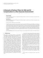
The combination of the quality of the cameras and the lighting of the environment also created
areas of some frames where interesting objects that could have been tracked had their initial positions
occluded by exceptionally bright lighting (such as the c offee mug on the counter). Beyond the
problems created by the quality of individual frames, the frame rate of 10 frames per second and
the quality of the cameras contributed to exceptional motion blur.
2.2. ICDSC SMART HOMES DATA SET 16
Figure 2.2: Frame from ICDSC 2009 Smart Homes Data Set
2.2. ICDSC SMART HOMES DATA SET 17
Figure 2.3: Effects of Motion Blur