NES5100 excitation regulator Hệ thống điều chỉnh kích từ NES5100
Bạn đang xem bản rút gọn của tài liệu. Xem và tải ngay bản đầy đủ của tài liệu tại đây (1.58 MB, 113 trang )
NES5100 Excitation
Regulator
User’s Guide
Electrical Control Branch, NARI Group Corporation
August 2008
Table of Contents
1. Overview 1
2. Hardware Configuration 8
3
.
Man-Machine Communication 20
4. Commissioning Procedure 69
5. Operation Procedure 75
6. Maintenance and Troubleshooting 92
NARI-ECC
1. Overview
1.1 Foreword
This Guide describes NES5100 excitation regulator.
This Guide consists of eight chapters and describes problems including
installation, maintenance and troubleshooting of the excitation regulator. The chapters
are described as follows:
1. Overview: installation engineer, commissioning engineer, operators and repair
and maintenance engineer must read Overview section of this Guide.
2. Configuration and setting: Commissioning engineer, repair and maintenance
engineer must read Configuration and Setting section.
3. Installation instruction: Installation engineer and repair engineer must read
Installation Instruction section.
4. Man-machine communication: Commissioning engineer, operator, repair and
maintenance engineer must read Man-Machine Communication section.
5. Commissioning procedure: Commissioning engineer, repair and maintenance
engineer must read Commission Procedure section.
6. Operating procedure: Operator must read operating procedure section.
7. Maintenance and troubleshooting: Operator, repair and maintenance engineer
must read Maintenance and Troubleshooting section.
8. Annex and drawings: Installation engineer, commissioning engineer, operator,
repair and maintenance engineer must read Annex and Drawings section.
The abovementioned documents constitute a collection of documents. This
Guide is intended to help users with correct installation, trail run, operation and
maintenance (including troubleshooting).
This Guide is available to users who have acquired adequate professional
1
NARI-ECC
knowledge of mechanical and electrical engineering.
Operators who carry out initial trial run and troubleshooting must be equipped
with professional technical knowledge, and refer to professional system hardware
drawings, and produce test and commissioning report.
Excitation regulator must be tested according to recognized test standard.
This Guide can help operator to discover failures.
Please replace failed modules (both board and power components) with spare
parts. Experts are usually required to carefully check system failure. Most of
important, the abovementioned documents must be kept complete and up-to-date in
order to ensure that all system information remain accurate and valid. Furthermore,
this Guide must be kept in a safe place.
1.2 The Purpose of this User’s Guide
Why you should read this Guide
Before putting Excitation System into operation, you should read this Guide because:
◆
Important notice related to operation and safety is available to you.
◆
You will find detailed technical information about excitation system and ways to
correctly complete operation.
◆
You will find ways to achieve stable operation and a prolonged service life of
system
1.3 How to Use this Guide
◆
Target user
This guide is targeted at operators and maintenance engineers of NES5100 excitation
regulator. Those who are responsible for operating and maintaining excitation
regulator should be well experienced in mechanical and electrical engineering. They
2
NARI-ECC
should attend excitation system-related training offered by Electrical Control Branch,
NARI Group. We suggest that repair engineer should regularly attend our training
course.
◆
Scope of this Guide
This Guide includes all information related to safety and correct operation of
NES5100 excitation regulator. Section 2 includes important information related to
operation and maintenance of excitation system.
This Guide consists of eight sections. This Guide will be supplied along with the
excitation regulator.
◆
Notice
Important notice always appears at the beginning of every paragraph or every
line in the paragraph
◆
Signs
Caution, danger! This caution sign indicates a possible source of
hazards that could cause serious personal injury or damage to the
equipment.
Caution: electric shock This caution sign indicates a possible
source of electrical hazards that could cause personal injury or
damage to the equipment.
Note This sign indicates all particularly important information.
Electrostatic charge This sign indicates that electrostatic charge may cause
damage to circuitry; do not touch electrical components
Caution, Hanging This caution sign indicates that hanging objects may
3
NARI-ECC
cause serious personal injury.
1.4 Safety Rules
Article 1 These Rules are established to ensure safety and health of staff and safe
operation of electrical system and equipment by summarizing and analyzing
experience in installation, operation, maintenance and repair of excitation equipment.
Leaders and electric engineers must strictly comply with these Rules.
Article 2 Safety is everybody’s business.
Article 3 These Rules apply to those who install, run, operate, repair and maintain the
excitation regulator. Various departments may establish complementary rules and
implement these rules upon the approval of executive in charge of production (chief
engineer).
Article 4 Electrical engineers must meet the following requirements:
◆
Without any disease that may impact their ability to work;
◆
With necessary electric knowledge, and be familiar with Working Regulation on
Power Safety and these Rules, dependent on their duties and nature of work;
◆
To have an intimate knowledge of how to prevent accidents; receive training on
first-aid and fire extinguishing system, and particularly first aid for electric shock.
Article 5 Those who install, run, operate, repair and maintain this excitation regulator
must study these Rules.
Those who perform electricity-related tasks should receive special training and work
upon the approval of the leaders.
New electrical engineers and practitioners and staff who temporarily (leader and
casual laborer) perform electricity-related tasks are not allowed to work until they
receive training on safety; they are not allowed to work independently; introduce
wiring of electrical equipment and safety to electricians who are sent to support a
temporary work program.
Article 6 If somebody has been found in breach of these Rules in a manner that is
4
NARI-ECC
serious enough to cause personal injury or damage to equipment, immediately prevent
him/her from doing so.
Article 7 Whenever service or work is performed on the equipment, please strictly
follow the safety rules.
Article 8 Whenever service or work is performed on the equipment, please follow the
lock-out/Tag-out procedure. Make sure that each of the following steps are taken.
◆
Disconnect power before servicing the equipment;
◆
Check to confirm that the equipment has no power by testing for voltage;
◆
Place a warning tag;
Article 9 Disconnect all electrical power to the equipment.
Article 10 Please test voltage with qualified electroscope; respectively test voltage on
both sides of the equipment. Before testing voltage, conduct a test in the equipment to
confirm that electroscope is in good working condition.
Article 11 Place a warning tag that reads, “UNDER REPAIR, DO NOT USE” on the
power source and on the equipment;
Article 12 A supervisor of electrical works should have practical experience in
electrical work.
Article 13 Keep test equipment away from equipment in operation; collision with
equipment could cause malfunction. Prevent the equipment from being vibrated or
collided when cleaning or operating it. Use insulated tools.
Article 14 In case of a fire where electrical equipment is present, immediately shut off
the electrical current and join the fight against fire.
1.5 Emergency Management
There is a danger of electric shock or short circuit when performing electrical
measurements in a high-voltage signal terminal of NES5100 excitation regulator.
Short circuit could cause malfunction of equipment and jeopardize the safety of
motors and electrical network. Maintenance engineer must perform electrical
measurements with caution. Never take a risk!
5
NARI-ECC
Such negligence could result in:
Serious personal injury or equipment damage.
1.5.1 Fire Management
All workers must know the location of fire extinguishers and
emergency exits and how to use a fire extinguisher. Fire extinguishers are
divided into the following categories: halogenated agent fire extinguisher,
Carbon dioxide fire extinguisher and foam fire extinguisher.
◆
Carbon dioxide fire extinguisher is used to extinguish a fire where electrical
equipment is present; Do not point carbon dioxide fire extinguisher at anyone
catching fire.
◆
Foam fire extinguisher
is used to extinguish a fire where electrical
equipment is absent. Foam fire extinguisher should not be used to extinguish a fire
where electrical equipment is present. You may point foam fire extinguisher at anyone
catching fire.
In case of a fire:
Disconnect all electrical power to excitation regulator by means of local or
remote control, and actuate emergency shutdown process (see Chapter 7: Operation
and Control for details), and shut off all equipment. Fires in current-carrying cabinet
can only be extinguished with carbon dioxide fire extinguisher. Never use water or
foam to extinguish a fire where electrical equipment is present!
1.5.2 First Aid for Electrical Injury
To give first Aid for electric shock, you must seize every minute and
second. At first, get the victim away from the source of the current as soon
6
NARI-ECC
as possible. The longer the current flows through the body, the more
serious the injury. Be extremely careful that you don’t become the next
casualty.
Do not touch the victim with your bare hands until you are sure that there is no
further danger to you or victim and the victim is no longer in contact with the
electrical source. As soon as the current is turned off, make sure that emergency lamp
is ready. New lamp must meet the requirements of fire and explosion prevention.
Make sure that current is immediately shut off, and first aid is immediately given.
If the victim is conscious, keep the person lying down and check for breathing
and pulse. Do not more the victim from his or her original position. If the victim is
unconscious, lay him or her down and keep his or her airway open. Spend 5 seconds
calling the victim or tap lightly on the shoulder in order to determine whether the
victim loses consciousness or not. Do not attempt to call the victim by shaking the
victim’s head. Administer proper first aid as needed. Summon help by calling
Emergency Medical Service.
1.6 Important Notice
According to our experience, following suggestions and instructions of this
Guide will greatly improve the reliability of our excitation regulator.
All information available on this Guide introduces our product and should not be
considered to have shown actual characteristics of our products. In order to meet
user’s requirements, we will continue to make every effort to keep us updated with the
latest technology trends. Therefore, there may be discrepancy between documents.
Although this Guide has been carefully examined, there are always glitches. Please
notify us immediately after you discover any mistakes in this Guide so that we can
make modification as soon as possible. It is impossible for this Guide to take into
consideration all possible problems with the use and installation of the equipment.
Therefore, please contact us immediately after you discover any problems that this
Guide fails to mention.
7
NARI-ECC
Follow this Guide and local safety rules to install, connect and commission the
equipment.
Such work as welding, moving jumper or resistance modification must be done
by trained professionals.
We hereby expressly declare that we will assume no responsibility or liability for
any damage caused by improper operation or installation even if this Guide fails to
specify this. We hereby point out that you must use original spare parts.
We reserve all rights for this Guide, including patent rights and other industrial
property rights. You must not use or copy this Guide to the third party.
1.7 Address of Manufacturerb
Electrical Control Branch, NARI Group Corporation
Address: 8 Nari Road, Nanjing
Post code: 210003
Tel: +86
(
0
)
25 58646173 Fax: +86
(
0
)
25 58646172
2. Hardware Configuration
2.1 Why you should read this Chapter
You will know about information related to main technical requirements of
NES5100 excitation regulator. In addition, this Chapter describes configuration and
settings of all equipment inside NES5100 excitation regulator.
8
NARI-ECC
2.2 Hardware Configuration of NES5100 Excitation
Regulator
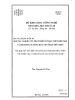
2.2.1 Block Diagram
Figure 2-1: Sketch Map of Card Connector of one NES5100 excitation regulator
Figure 2-1: Sketch Map of Card Connector of one NES5100 excitation regulator
See Table 2-1 for name of boards:
Board No. Board name
EX01 Pulse power board
EX02 System power board
EX03 CPU board
EX04 Analog board
EX05 Synchronizing voltage board
EX06 Digital board
EX07 Extended binary board
EX08 Pulse amplification board
Table 2-1: Name of single board
See Figure 2-2 for block diagram of hardware of NES5100 excitation regulator.
A channel is usually equipped with a set of transformers; the other set of transformers
are not shown in Figure 2-2.
9
NARI-ECC
Figure 2-2: Controller of automatic twin-channel and independent manual channel
See Figure 2-3 for Block Diagram of Local Area Structure of NES5100 Excitation
Regulator.
图
2-3 NES5100
图图器局域图图方图图
Figure 2-3: Block Diagram of local area structure of NES5100 Excitation Regulator
A
套:
Regulator A B
套:
Regulator B
图
CAN: Dual-channel CAN communication
交图机:
Exchanger
工控机:
Process control computer
图方图控:
Remote monitoring
10
NARI-ECC
2.2.2 Overview
The normal modes supplied for controlling excitation are automatic voltage
regulation (AVR) and field current regulation (FCR).
Automatic voltage regulation is abbreviated as AVR mode; field current
regulation is abbreviated as FCR mode. After field flashing of generator, two
regulation modes will track each other. Standby regulation mode tracks operating
mode. The basis for tracking is that two regulation modes have equivalent output and
this kind of tracking relationship can not be cancelled manually.
Two operating mode can be switched manually. Under certain circumstance such
as PT failure, two operating mode can be changed over automatically.
NES5100 is equipped with an independent manual channel. Both hardware
channel and configuration of software functions are independent. In case of automatic
channel failure or manual switch, regulator can operate under manual channel.
One channel is in on-line operation and the other is in hot standby. Both are
monitoring their functions without disturbing the operation.
2.2.3 Functions and Configuration of Hardware
2.2.3.1 EX01 Pulse power board
EX01 pulse power board is used to supply +24v power output by pulse. See
Figure 2-1 for block diagram and view.
11
NARI-ECC
Figure 2-1: Block Diagram and View of EX01 Pulse Power Board
In order to ensure reliability of excitation system, EX01 pulse power board is
manufactured by professional manufacturer according to military standard. In
addition, we take into consideration prevention of electromagnetic interference,
prevention of dust and heat radiation. It has passed strict EMC test and high-
temperature test.
2.2.3.2 EX02 System Power Board
EX02 system power board: EX02 system power board has double power source:
AC220V, DC220V (or DC110V) input, +5V and 24V output for digital board;
See Figure 2-2 for Block Diagram and View.
In order to ensure reliability of excitation system, EX01 pulse power board is
manufactured by professional manufacturer according to military standard. In
addition, we take into consideration prevention of electromagnetic interference,
prevention of dust and heat radiation. It has passed strict EMC test and high-
temperature test
12
NARI-ECC
Figure 2-2: Block Diagram of View of EX02 Pulse Power Board
2.2.3.4 EX03 CPU Board
◆
Basic features
EX03 CPU board is the central control board, with the following functions:
●
Convert analog signal into digital signal, and sample analog signal;
●
Compute and produce small pulse according to the results of A/D sampling
and input signal logics;
●
Send output signal to digital signal;
●
Measure frequency and detect pulse read-back;
●
Realize switch between regulator A and regulator B, and switch from
manual mode to automatic mode;
●
Communication function;
Please see Figure 2-3 for block diagram and view:
13
NARI-ECC
Figure 2-3: Block Diagram and View of EX03 CPU Board
◆
A/D converter
Convert analog signal regulated by EX04 analog board and EX05 synchronizing
voltage board into digital signal. Automatic channel uses 16-bit bi-polar multi-channel
analog-to-digital converter (ADC) manufactured by AD Corporation. This analog-to-
digital converter features low power consumption (160mW), which is 60% down as
compared with bi-polar analog-to-digital converter of its kind. The AD7656 analog-
to-digital converter contains a low-noise wideband track and hold amplifier so as to
process signal with input frequency being as high as 8Mhz. The AD7656 analog-to-
digital converter has high-speed parallel interface and serial interface, allowing
connection between the analog-to-digital converter and microprocessor or digital
signal processor.
Working in collaboration with MAX309 multiway switch manufactured by
Maxim Corporation, this analog-to-digital converter realizes synchronizing sampling
of one-way three-phase voltage and three-phase current, which ensures accurate
measurement of reactive power.
Manual channel is equipped with 12-bit analog-to-digital converter which
samples field current.
◆
Control chip
Automatic channel uses control core comprising 32-bit ARM chip and large-
scale programmable control chip (
FPGA)
. To control and compute according to A/D
sampling results and input signal logics, and send control pulse and output digital
14
NARI-ECC
signal, measure frequency and detect pulse read-back.
32-bit ARM chip has a powerful communication function and support
communication protocol including Ethernet 10/100M Base-T and USB2.0.
Automatic channel uses 16-bit DSP as control chip to complete analog signal
sampling and produce pulse.
◆ Pulse switch
When NES5100 excitation regulator operates normally, automatic channel and
manual channel will send control pulse according to computation, and then judge
whether the control pulse is from automatic channel or manual channel, and then send
the control pulse to pulse amplification board. Please see Figure 2-4 for block diagram
of pulse change-over.
图
2-4
图图切图图图
Figure 2-4: Block Diagram of Pulse Switch
自图通道图图:
Pulse from automatic channel
图图图出:
Pulse output
手图通道图图:
Pulse from manual channel
多路图图:
Multiway switch
图图切图图图:
Pulse change-over logic
◆
CAN communication hardware design
Dual-channel CAN communication is applied to communication between
excitation regulator A and excitation regulator B. CAN controller uses independent
CAN controller SJA1000 chip manufactured by Philips. SJA1000 chip is a bus
interface. Compared with ARM controller, Storage unit inside SJA100 chip is a data
storage device outside the chip. Therefore, operator can access register of SJA1000
chip in the form of data storage device outside extension chip. ARM controller uses
GAL address decoder to select the correct location on SJA1000 chip and uses address
15
NARI-ECC
bus to accomplish the selection, and locates registers of CAN controller. By reading
and writing external memory, operator can have an access to SJA1000 chip. P82C250
transceiver manufactured by Philips is used as CAN transceiver. PCA82C250
transceiver is the interface between CAN protocol controller and physical bus.
PCA82C250 transceiver makes bus a differential transmitter and CAN controller a
differential receiver. PCA82C250 transceiver makes it possible to control both CAN
networks and reach transmission speed as high as 1Mb/s.
◆ Ethernet hardware design
◆
Function setting
If you uncover the front cover board of EX03 board, you can see a DB serial
interface and four dial switch. Serial interface can be used to download program and
parameters. Functions of dial switch are described as follows:
●
Internal/external start
●
Automatic/manual
●
Selection of serial interface
●
Operation/commissioning
2.2.3.5 EX04 Analog Board
EX04 analog board can perform signal conditioning; EX04 analog board can
condition the following signals: terminal voltage, system voltage, synchronizing
voltage, stator current, rotor current, etc. Conditioning is to isolate and convert high-
peak voltage (100V) and high-peak current (5A) signal into ±10V voltage signal and
transmit the signal to CPU board; EX04 analog board also includes 4-channel 12-bit
D/A output;
Figure 2-5 shows Schematic Circuit Diagram of one-channel voltage signal;
UF1A-IN is 100V voltage signal which is converted into ±10V voltage signal after
circuit conditioning.
16
NARI-ECC
1 2 3 4 5 6
A
B
C
D
654321
D
C
B
A
Title
Number RevisionSize
B
Date: 11-Sep-2006 Sheet of
File: E:\oftenbrowser\NES5100\drawings\电电电电电电 \电电电电\an-v3.DdbDrawn By:
3
2
1
8 4
A
-12V
12V
1 3
2 4
SPT1
UF1A-IN
S1
Ufa
3
2
1
8 4
A
12V
-12V
XUFA
Figure 2-5: Schematic Circuit Diagram of Voltage Signal Conditioning
Figure 2-6 shows Schematic Circuit Diagram of Current Signal Conditioning;
IFA-IN is signal of high-peak current (maximum value: 5A); after circuit
conditioning, the current signal is converted into ±10V voltage signal.
1 2 3 4 5 6
A
B
C
D
654321
D
C
B
A
Title
Number RevisionSize
B
Date: 11-Sep-2006 Sheet of
File: E:\oftenbrowser\NES5100\drawings\电电电电电电\电电电电\an-v3.DdbDrawn By:
3
2
1
8 4
U1A
XIFA
SCT4
-12V
12V
IFA-IN
Figure 2-6: Schematic Circuit Diagram of Current Signal Conditioning
EX5100 excitation regulator also measures no-load electromotive force E; See
Figure 2-7 for schematic circuit diagram.
2.2.3.6 EX05 Synchronizing Voltage Board
EX05 Synchronizing Voltage Board: The main function of EX05 synchronizing
voltage board is to convert synchronizing voltage (high voltage: 100V) signal and
transmit it to CPU board. For different synchronizing frequency, select different
parameters of jumper and resistance capacity components;
17
NARI-ECC
2.2.3.7 EX06/EX07 Digital Board
There are 20-channel digital input through optical coupler isolation and 16-
channel digital output in EX06/07 digital board. Binary; after optical coupler
isolation, 16-channel binary output through relay contacts; binary board has powerful
display function; status of every digital can be indicated by lamp on the panel.
Therefore, you can observe status of digital board.
EX07 digital extension board has the same hardware and functions as EX06
binary board.
1 2 3 4 5 6
A
B
C
D
654321
D
C
B
A
Title
Number RevisionSize
B
Date: 11-Sep-2006 Sheet of
File: E:\oftenbrowser\NES5100\drawings\电电电电电电\电电电电\io.ddbDrawn By:
I1-IN
3
4
14
13
B
24VI
GNDI
I1-in
Figure 2-: Schematic Circuit Diagram of Digital Input
2.2.3.8 EX08 Pulse Amplification Board
The main function of pulse amplification board is to amplify and output small
pulse formed in CPU board by sending small pulse to 6 CMOS thyristor through
photoelectric isolation and level conversion. Pulse change-over relay primarily
controls whether to output pulse. Normally closed contacts can ensure that pulse can
still be output when operating power source is disconnected The other function of
pulse amplification board is to sample pulse and return it to CPU board to check to
see if pulse has been lost. Pulse amplification board also has functions of power
source test and failure detection. Function of power source test can test +5V, ±12V
and 24V power source; if power down or power failure is detected, immediately
remove the failure and switch two equipment so as to ensure reliability of the system.
18
NARI-ECC
Figure2-: Schematic Block Diagram and View of Pulse Amplification Board
图 2- 图图放大板的原理图图和图图
Figure 2-: Schematic Block Diagram and View of Pulse Amplification Board
小图图信图
: Small pulse signal
图图放大
: Pulse amplification
大图图信图
: Big pulse signal
功率图
: Power cabinet
图源图图
: Power source detection
图图回图图图
: Pulse read-back detection
主图图图
: Master/slave logic
图图放大板
: Pulse amplification board
CPU
板
: CPU board
2.3 Safety Precaution
Before touching single board, make sure that human body is properly grounded
in order to neutralize electrostatic charge. Electrical equipment is sensitive to
electrostatic charge. Follow safety rules at any time. Place single board in a bag with
function of electrostatic shield.
19
NARI-ECC
3
.
Man-Machine Communication
3.1 Why You should Read this Chapter
This chapter includes all information about man-machine communication of
NES excitation regulator. Please carefully read this Chapter before operating the
regulator.
Through man-Machine communication, operator can finish the following works:
◆
Display signal and operating data
◆
Display and set parameters
◆
Change operating mode of NES5100 excitation regulator
◆
Observe and record step test and step test waveform, failure waveform and
real-time signal waveform
◆
Modify application software
◆
Input and store parameters in the disk
Parameter setting and modification of application software requires user to have
an intimate knowledge of the system and can only be performed by those who have
received relevant training.
3.2 Man-Machine Communication Tools
3.2.1 Overview of NES_HMI
NES-HMI intelligent monitoring software system (hereinafter referred to as
20
NARI-ECC
NES_HMI) is developed by Electrical Control Branch under Nanjing Automation
Research Institute/Electrical Control Corporation under NARI Group Corporation for
NES5100 excitation regulator. This software system consists of intelligent excitation
monitoring software and communication middleware OPC Server for NES5100.
NES_HMI consists of the following modules: system topology view module,
failure log module, parameter setting module, over-excitation and under-excitation
curve module, waveform recording module, sampling oscilloscope, step response
module, parameter comparison module, communication variable configuration
module. NES_HMI can successfully fulfill the operation monitoring and
commissioning requirements of excitation regulator.
3.2.2 Installation and Operation of NES_HMI
3.2.2.1 Minimum System Configuration for NES_HMI
◆
CPU Pentium 166MHZ
◆
Memory: 64MB
◆
Hard disk: 1.0GB
◆
Display: VGA; 16-bit true color; 800*600DPI
◆
Operating system: WINDOWS 2000 or XP (Chinese version)
3.2.2.2 Recommended System Configuration for NES_HMI
◆
CPU Pentium II 300 MHZ
◆
Memory: 256MB
◆
Hard disk: 10GB
◆
Display: VGA, 16-bit true color; 800*600DPI
◆
Operating system: WINDOWS 2000 or XP (Chinese version)
21
NARI-ECC
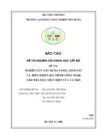
3.2.2.3 Installation and Operation of NES_HMI
NES_HMI intelligent excitation monitoring software system is installed as follows:
1. Run setup.exe, then window will pop up as shown in Figure 4-1.
Figure 4-1: Installation Process 1
2. Click “next” button
22
NARI-ECC
Figure 4-2: Installation Process 2
3. Read the Service Agreement, select “ I Accept” and click “next” button
图
4-3
安图图程
3
Figure 4-3: Installation Process 3
23