ss7 call flow diagraams
Bạn đang xem bản rút gọn của tài liệu. Xem và tải ngay bản đầy đủ của tài liệu tại đây (213 KB, 18 trang )
SS7 Call Flow Diagrams
Contents:
I. Intoduction to SS7 and general Mobile network Architecture
II. GSM & GPRS (2G, 2.5G & 3G) Call flows
1. Authentication & Location Update
2. Location Cancellation
3. MO call (Mobile to PSTN)
4. MT call (PSTN to Mobile)
5. a. SMS MO
b. SMS MT
II. Prepaid CAMEL Call flows
i) MO call (Mobile to PSTN)
ii) MT call (PSTN to Mobile)
2
I. Intoduction to SS7 and general Mobile network Architecture
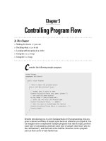
♦ SS7 signalling and its application parts are used to establish the communication
path between the operators. The SS7 protocol follows the OSI model. Refer to the
diagram below.
♦ SCCP (Signalling Connection Control Part) is the most suitably used for routing
of messages from a HPLMN network to a VPLMN network and vice versa in
GSM. SCCP provides advantage over MTP Level 3 routing. MTP L3 does routing
based on OPC and DPC which means it allows messages to be addressed to two
signalling points only. Whereas SCCP provides subsystem numbers to allow
messages to be addressed to specific applications (called subsystems) at these
signalling points.
SCCP also provides the means by which an STP can perform global title
translation (GTT), a procedure by which the destination signalling point and
subsystem number (SSN) is determined from digits (i.e., the global title) present
in the signalling message.
♦ TCAP is a transport layer protocol which uses SCCP to establish concurrent
dialogs between the same sub-systems on the same signaling points , using
Transaction IDs to differentiate these, similar to the way TCP ports facilitate
multiplexing connections between the same IP address on the internet
♦ In a Mobile network, TCAP is used to transport various application parts like
MAP, INAP and CAP.
3
SS7 Protocol Stack Functions of each layer
SCCP
MTP LEVEL 2
MTP LEVEL 3
TCAP
I
S
U
P
INAPCAPMAP
4
Defines the physical, electrical, and functional characteristics of
the digital signalling link. Physical interfaces defined include E-1
(2048kb/s; 32 64 kb/s channels), DS-1 (1544 kb/s; 24 64 kb/s
channels), V.35 (64 kb/s), DS-0 (64 kb/s), and DS-0A (56 kb/s).
Accurate end-to-end transmission of a message across a
signalling link. Implements flow control, message sequence
validation, and error checking. When an error occurs on a
signalling link, the message (or set of messages) is retransmitted
Provides message routing between signalling
Points in the SS7 network. MTP Level 3 re-routes traffic away
from failed links and signalling points and controls traffic when
congestion occurs.
MTP LEVEL 1
SCCP is a sub-part of other L4 protocols, together with MTP 3 it
can be called the Network Service Part (NSP), it provides end-to-
end addressing and routing, connectionless messages (UDTs),
and management services for the other L4 user parts.
The ISDN User Part (ISUP) provides the protocol and
procedures to set-up, manage, and release trunk circuits that
carry voice and data calls over the public switched telephone
network (PSTN) or ISDN network.
TCAP is used to create database queries and invoke
advanced network functionality, or links to intelligent networks
(INAP), mobile services (MAP), CAMEL Application Parts
(CAP) etc.
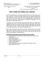
SGSN
GGSN
MSC/VLR
IP
Network
GPRS
Backbone
BG
BG
Other
PLMN
SGSN
GGSN
BG
BG
SS7
BSC/RNC
BTS/Node-B
HLR/AUC
2.5G & 3G Network. Only in the case of 3G, the
WCDMA radio access technology is used and a
BSC is called RNC and BTS is called Node-B
2.5G & 3G Network. Only in the case of 3G, the
WCDMA radio access technology is used and a
BSC is called RNC and BTS is called Node-B
5
♦ The Mobile network can be broadly divided into two parts: Core Network and
Radio Access network.
♦ The Core network does call control, call routing and call charging.It is also a
gateway to the external networks like PSTN and an interface to other services like
SMS, Voicemail and Billing etc.
♦ The Radio Network gives the Mobile Station (MS) the wireless access into the
network.
♦ The Voice Core network is the same whether it is 2G, 2.5G or 3G. For Data calls,
a Packet switched Core network is used but the Radio access differs. The entire
network Gs (generations) are basically classified on the basis of the rate of
data transfer over the radio interface. The slower the rate, the older the
generation!
♦ 2G: RAN consists of BSC and BTS and only circuit switched voice and data are
supported. TDMA is the access method used. 2G uses a carrier bandwidth of 200
KHz on the air interface. SS7 is widely used in Core and Radio networks. The
Voice and data are both circuit switched. The rate of a data call is maximum
9.6Kbps.
♦ 2.5G & 2.75G: To facilitate increased rate of data calls in a GSM network, two
technologies were evolved : GPRS and EDGE. GPRS has a separate core
network, all IP based, parallel to GSM Core. While GSM is responsible for
Circuit switched call routing, GPRS is based on packed switching and is used
explicitly for data calls and services like MMS, WAP internet. To accommodate
the packet switching, a minor hardware and software upgrade and configuration in
the existing GSM RAN (BSC and BTS) is all that makes it a 2.5G network! The
download data rate can be as high as 80Kbps.
Unlike GPRS, EDGE (2.75G) is an enhancement of 2G GSM circuit switch
technology and provides 3 times higher data rate than GPRS. Some minor
hardware and software modifications are required in the BTS.
♦ 3G: Also referred to as UMTS, the services associated with 3G provide the ability
to transfer simultaneously both voice data (a telephone call) and non-voice data
(such as downloading information, exchanging email, instant messaging and
video telephony).
3G uses 5 MHz channel carrier width to deliver significantly higher data rates and
increased capacity compared with 2G networks. Technically, W-CDMA is used in
3G. It is a wideband spread-spectrum mobile air interface that utilizes the direct
sequence Code Division Multiple Access signaling method (or CDMA) to achieve
higher speeds and support more users compared to the older TDMA signaling
method of GSM networks.
♦ IN & CAMEL: Intelligent Networks basically form an overlay to the core
network. Using IN, an operator can provide value added services in addition to
the GSM services to the customers. Examples of such services are Toll Free calls
and prepaid calls. The IN concepts, architecture and protocols were developed
6
originally as standards by the ITU-T. The aim of the IN is to enhance the core
telephony services offered by traditional telecommunications networks, which
usually amounts to making and receiving voice calls and call divert.
The main concepts surrounding IN services or architecture are:
Service Switching Point (SSP). This is co-located with the MSC and acts as the
trigger point for further services to be invoked during a call.
Service Control Point (SCP). It receives triggers from the SSP. It has the main
service logic and processes a call based on the logic as desired by the operator.
Service Data Point (SDP). This is a database that contains additional subscriber data,
or other data required to process a call. For example, the subscriber’s prepaid credit
which is remaining may be an item stored in the SDF to be queried by the SCP in real
time during the call. The SDF may be a separate platform, or is sometimes co-located
with the SCP.
Service Creation Environment (SCE). It’s the environment used to create the
services present on the SCP. It provides a front end to the operator.
Intelligent Peripheral (IP). This is a node, sometimes co-located with in the SSP,
which provides additional resource and services to an IN call like collect DTMF
(Dual Tone Multi Frequency) from user or play announcements.
In Mobile networks, CAMEL is the widely used IN application protocol. Camel
Application Part (CAP) of SS7 is used to implement the CAMEL function between
the SSP and the SCP. All other interfaces in an IN are usually IP based or proprietary
to the Vendor.
I. GSM & GPRS Call Flows
CAMEL
Intelligent NetworkIP
SS7
SCE
SSP
MSC
Internal
Protocol
Internal
Protocol
Internal
Protocol
SDP
SCE
7
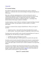
1) Authentication & Location Update
1. The MS sends a Location update request on the air along with its IMSI and last Location
Area Identity (LAI).
2. The request from the MS is forwarded to the MSC/VLR by the RAN.
3. If the IMSI data is loaded in the MSC/VLR, the MSC does a Global title translation i.e.
converts MCC+MNC to MGT to obtain the HLR address of the roaming subscriber. The
resulting translation is in the format E.214 and is used to address the HLR for requesting the
Authentication Information. The IMSI and the requesting VLR address are sent to the HLR.
4. On receipt of the request, the HLR obtains the Auth triplets (for 2G with MAPver2) or Auth
Quintuplets (for 3G with MAP ver3) from AUC and forwards it to the VLR.
Triplets RAND, SRES & Kc. Quintuplet RAND, SRES, CK, IK & AUTN
5. The VLR then requests the SIM, through the MSC & RAN, for the authentication.
6. The MS calculates the SRES and sends back to the network. If this SRES is same as the one
received by the VLR in the Triplets sent by HLR, the authentication succeeds and the
Location update request is sent back to the HLR. If Authentication fails, no LU request is
sent by the VLR to HLR.
7. After Authentication is successful, VLR sends LocUpd request to HLR.
8. HLR sends all the services like speech, SMS, APNs etc that are provisioned on the SIM in
“InsSubData” MAP message to VLR.
10.LocUp 10. UpdLocAck
3.SndAuthInfo
7.LocUpd
9 InsSubDataAck
8 .InsSubData
4.SndAuthInfoResp
6.AuthResp
5.AuthReq
2.LocUpReq
1.LocUpReq
10.UpdLocAck
6. AuthResp
5.AuthReq
RAN VMSC/VLR HLRMS GMSC
BSSAP
GSM MAP
8
9. The VLR inserts all the data into it and acknowledges the HLR
10. The HLR finally confirms the location update to the VLR. At the same time the HLR stores
the VLR address to keep track of the current location of the MS
Common causes for Authentication Failure:
1. SIM is unknown in HLR/AUC i.e., it is not activated.
2. Auth_Req to USIM with MAP ver2 fails since USIM stores only Quintuplets and can
authenticate on MAP ver3 only
Common causes for Location Update Failure:
1. “Roaming not allowed” cause received from HLR if IR is not
provisioned in the HLR.
The home carrier should provide the service before testing.
2. HLR sends some service in ‘Insert Sub Data’ which is not supported in VLR. This leads
VLR to abort the communication. Services like CUG, PLMN specific barring are mostly
rejected by VLRs. The HPLMN tester should be requested to remove such services on the
test SIM
9
2) Location Cancellation
1. This service is used between HLR and VLR to delete a subscriber record from the
VLR.
2. It may be invoked automatically when an MS moves from one VLR area to
another, to remove the subscriber record from the old VLR, or by the HLR
operator to enforce a location updating from the VLR to the HLR, e.g. on
withdrawal of a subscription.
2. LocUpdReq
2. UpdLocAck
2. Loc_CancelAck
2. Cancel_Loc
1. Cancel_Loc
1. Loc_ CancelAck
Old VLR New VMSC/VLR HLRMS GMSC
BSSAP
GSM MAP
10
3) Mobile Originated Call (Mobile to PSTN)
1. The MS requests the call setup for MOC. This request is also used for a channel allocation for
the call in the air and A interface. Request message contains the called party address.
2. MSC analyses the called party digits, obtains the route from the B-Number analysis table and
shoots Initial Address Message to the destination PSTN. The IAM contains Calling party, called
party and other info like CLIR etc.
3. The PSTN exchange analyses the B-number, if correct, then sends Address Complete Message
to the GMSC.
4. While the B-number is being alerted (ring) , a Call Progress may be sent back to the GMSC
5. When the PSTN answers the call, an ANswer Message is sent by the terminating PSTN
exchange. This is also the point when charging starts in the MSC.
6. If the MS disconnects the call, a RELease message is sent to the PSTN. If the PSTN disconnects
first, then REL is sent by the PSTN
7. To acknowledge the REL, a Release Complete message is sent. The pair REL and RLC is
required to clear the circuit connections currently held by the call.
8. Finally the air interface channel occupied by MS is released.
Common causes for MOC failure:
1. Outgoing call barring is active on SIM and hence MSC rejects the call.
2. B-number is not configured/routed in the MSC and hence MSC cannot route the call.
3. There is congestion in the national/International Network.
6. REL6. REL6 Disconnect
5. ANS 5. ANS 5. ANS
4. CPG4. CPG4. Alerting
3. call proceeding 3. ACM3. ACM
2. IAM2. IAM
1. Setup
VMSC/VLRMS GMSCRAN
PSTN
Exchange
8. Release 7. RLC 7. RLC
BSSAP
ISUP (circuit
related)
11
4) Mobile Terminated Call (PSTN to Mobile)
1.1. The calling PSTN sends IAM to the GMSC of the called MS. Regardless of the location of
PSTN in Home country or anywhere else is the world, the call is first routed to the Home
GMSC via intermediate exchanges/carriers by doing digit analysis of the called number. The
main components of IAM are OPC, DPC, Calling, Called and other optional parameters.
2.1 After receiving the IAM, the GMSC does a B-Number digit analysis to find the appropriate
HLR and send a MAP message SRI – Send Routing Info to the HLR. The SRI contains the
MSISDN, GMSC address and other parameters.
2.2 Once SRI request is received, the HLR checks the current VLR address in its dynamic data
table for the MS and sends MAP message PRN – Provide Roaming Number to the VLR. This
is a request to obtain the MSRN from the VLR
4.3. Release
1.5. RLC
1.4.REL
3.4. REL
3.3. ANM
4.2.PAGINGResp,setup
4.1.PAGINGReqst
3.2. ACM
3.1. IAM
2.4. SRIResp
2.3. PrvdRoamNumResp
2.2. PrvdRoamNum
2.1. SRI
1.2. ACM
1.1. IAM
PSTN(home n/w)MS GMSC(home n/w)RAN VMSC/VLR
1.3.ANM
3.5. RLC
ISUP (circuit related)
GSM MAP
BSSAP
12
HLR
(home n/w)
2.3 The VLR responds with an MSRN in PRN response MAP message to the HLR. It also stores
this MSRN against the IMSI for use in call setup.
2.4 The HLR forwards the same MSRN to the GMSC and closes the SRI procedure.
3.1 The GMSC now does a MSRN digit analysis and if found, routes IAM to the appropriate
VMSC. The IAM contains the MSRN as the Called party. Internationally, this call is handled
and routed by various intermediate carriers.
3.2 The VMSC, upon digit analyses, sends ACM- Address Complete Message to the Calling
GMSC.
4.1 The VMSC obtains the LAC of the MS from VLR, then sends a Paging Request to the relevant
BSC at which the MS is located currently
4.2 The BSC pages the MS and if the MS is attached to the network, it send back the Paging
Response to the BSC. The BSC inturn confirms that same to the GMSC. The call is then setup,
alerted and then connected when the MS answers the call.
3.3 An ANM – Answer Message is sent to the GMSC to confirm the connection and this is where
the conversation starts
1.3. An ANM is also sent simultaneously by the GMSC to the originally calling PSTN exchange.
1.4, 3.4. REL- RELease message is sent on both the ISUP legs once the call is released.
1.5, 3.5, 4.3. Once the call is released, RLC- ReLease Complete is returned and the call is also
cleared on the MS side.
4.3. The traffic channel held by the MS on the air is finally released.
Common Causes for MTC failure
1. The MSRN digit analysis is not done in the Home GMSC.
2. There are delays is International Network due to which the call timer expires causing
the call to be unsuccessful
13
5) a. SMS MO
b. SMS MT
a.1 The MS sends the SMS Submit request to the VMSC. This request contains the originating
MSISDN, the SMSC address to which it is submitted to, the destination MSISDN and the contents of
the Short Message.
a.2 VMSC forwards the Short Message to the SMSC in MO_FRW_SM MAP message. Once the SMS is
submitted successfully to the SMSC, the MS sees “message sent” report on the handset. This completes
the SMS MO request.
b.6. SM transfer
HLR
(home n/w)
a.1 SMS_SUBMIT
b.5. PAGINGResp
b.4. PAGING
b.3 MT_FRW_SM
b.2. SRI_Resp
b.1. SRI_FOR_ SM
a.2. MO_FRW_SM
VMSC/VLR GMSC (home n/w)RAN
SMSC-Gwy
(home n/w)
MSAMSB
GSM MAP
BSSAP
14
b.1 The SMSC sends the B-party MSISDN to the HLR for obtaining its routing information in MAP
SRI_FOR_SM request.
b.2 In SRI_Resp, the HLR returns the current VLR and MSC address of the B-Party to the SMSC.
b.3 SMSC now requests the MSC to forward the SMS to the MS through the MAP MT_FORW_SM
request.
b.4 MSC obtains the current LAC from the VLR and then sends Paging request to the BSC in whose area
the MS is located
b.5 MS responds to the paging and indicates its availability in the network.
b.5 Finally the SMS is delivered to the MS by the MSC.
Common Causes for SMS Failure
a. SMSMO:
1. The SMSC centre number in the MS is incorrect. Note that the SMSC centre number should
always be the home SMSC number and not the Visited network’s SMSC number.
2. The SMS MO service which is TS22 is not provisioned on the MS.
b. SMSMT
1. The HLR of the receiving MS has not configured the SMSC GT of the sender’s network.
This is required in order to return the SRI response to the originating SMSC.
2. If the MS memory capacity is exceeded then the SMS is delivered only when the memory is cleared.
3. If the MS is switched off or not in coverage, the SMS is kept stored within the SMSC and
forwarded again when the MS comes back to the network.
15
II. Prepaid CAMEL.
i) MO Call
2. IDP
6. ACH, CUE
16
MS GMSC/VLR/SSP
CAP (CAMEL)
ISUP (circuit related)
i) MT Call
17
PSTN VMSC/VLR GMSC/SSP
HLR
18