tekla tutorial lesson 11b assembly and single part drawings
Bạn đang xem bản rút gọn của tài liệu. Xem và tải ngay bản đầy đủ của tài liệu tại đây (1.36 MB, 43 trang )
Assembly and Single Part
Drawings
Tekla Structures 11.0 Basic Training
May 18, 2005
Copyright © 2005 Tekla Corporation
Copyright © 2005 Tekla Corporation TEKLA STRUCTURES BASIC TRAINING
i
Assembly and Single Part Drawings
Contents
11 Assembly and Single Part Drawings 3
11.1 Integration between Drawings and the Model 4
11.2 Create Drawings Using Drawing Wizards 5
11.3 Edit Drawing Properties 13
11.4 Create a New Drawing Wizard 27
11.5 Edit Drawings Manually 33
11.6 Update Drawings 37
11.7 Create Drawings Manually 41
Copyright © 2005 Tekla Corporation TEKLA STRUCTURES BASIC TRAINING
3
Assembly and Single Part Drawings
11 Assembly and Single Part
Drawings
We will introduce the creation of assembly and single-part drawings in Tekla
Structures.
We will first create single-part and assembly drawings by using predefined drawing
wizards (drawing wizards are an automatic way of creating single, assembly and
multi-drawings).
We will then edit the drawing properties and create a new drawing wizard. The
Drawing Wizard will use the edited drawing properties and the select filters that we
defined in an earlier lesson. Then we will show how the same drawings can be
created manually. We will also demonstrate how updating effects the drawings.
Revision control of all drawing types is presented in Lesson 10 Principles of
working with drawings.
In this lesson
Copyright © 2005 Tekla Corporation TEKLA STRUCTURES BASIC TRAINING
4
Assembly and Single Part Drawings
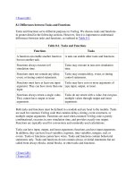
11.1 Integration between Drawings and the Model
Assembly and single-part drawings
Single-part drawings are workshop drawings of each of the individual steel parts in
the model. Assembly drawings are workshop drawings, in which details of an
assembly consisting of the steel parts are presented for fabrication.
All of the views in single-part or assembly drawings are current views of the
members as they are in the model.
When the model contains any identical members, the drawing is a view of one of
these members. The drawing, however, contains information about the quantity of
all of the identical members. If the "host" member of the drawing is modified or
deleted, it will get a new position mark at the next numbering. Tekla Structures will
then automatically assign the original drawing to another member with the original
position mark.
Tekla Structures integrates the drawings and reports with the model. This means
that, for example, dimensions and marks in the drawings are always correct.
Because the information in the drawings and reports comes directly from the model,
you cannot delete any of the parts or bolts from the drawings. You can, however,
filter out parts and bolts in the drawings, or make them invisible.
You can create drawings and reports at any stage of the project. If you change the
model, Tekla Structures updates the related drawings the next time you perform
numbering.
For more information, see
Help: Drawing > Introduction to drawings > Basics.
Copyright © 2005 Tekla Corporation TEKLA STRUCTURES BASIC TRAINING
5
Assembly and Single Part Drawings
11.2 Create Drawings Using Drawing Wizards
Once you have numbered the model, you can create assembly and single-part
drawings from the model. Drawing wizards are the most effective way to create
drawings in Tekla Structures.
Wizards automatically produce different types of drawings of different parts, such as
beams, columns, and braces. You can use wizards to create single-part, assembly, or
multi-drawings using the settings defined in the wizard files.
You can use the predefined wizard files, edit them, or create your own drawing
wizards. The
Wizard dialog box lists the available wizard files.
For more information on drawing wizards, see:
Help: Drawing > Getting started with drawings > Creating drawings > Using drawing
wizards
Help: Drawing > Getting started with drawings > Drawing reference > File>Wizard…
Drawing wizards cannot be used to create General
Arrangement (GA) drawings or cast unit (CU) drawings of
concrete structures.
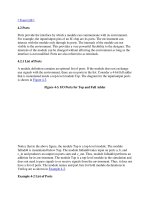
Functionality of drawing wizards
For each member type in the model, drawing wizards automatically perform the
following steps:
1. Define the drawing type to be created (single, assembly or multi)
2. Select the predefined drawing properties to be used
3. With the given select filter, select the parts from which to create drawings
4. Create drawings
Copyright © 2005 Tekla Corporation TEKLA STRUCTURES BASIC TRAINING
6
Assembly and Single Part Drawings
When you apply a wizard, you can choose whether the wizard creates drawings from
all parts of the model, or just from the selected parts.
By creating wizards that match the select filters and drawing
properties in the project you can automatically create all
single and assembly drawings of the parts using suitable
predefined properties.
Preconditions of using a drawing wizard:
• Numbering of the model must be up to date
• The appropriate wizard file must exist
• The saved drawing properties listed in the wizard file
must exist
• The saved select filters listed in the wizard file must exist
• Model members which will be selected by the select filter
must exist
Create single-part drawings of selected parts
We will now use a drawing wizard to create single-part drawings of selected steel
beams and plates.
1. Open the BasicModelCombined model.
2. Select the BEAM_STEEL filter from the drop-down list of available Select
filters
3. Select the whole model with an area selection
4. To see the creation of the drawings, open the drawing list by clicking the Open
drawing list icon.
5. Select File > Wizard… from the menu or click on the Wizard icon on the Standard
toolbar to open the
Wizard dialog box.
6. Select Single Drawings on the Wizards tab.
Create single-part
drawings of steel
beams
Copyright © 2005 Tekla Corporation TEKLA STRUCTURES BASIC TRAINING
7
Assembly and Single Part Drawings
7. Click the Create from selected button.
8. In the drawing list check that single-part drawings with the title BEAM were
created.
9. Open a few single-part drawings for viewing
You can view the next drawing on the list by clicking
Next or using the shortcut Ctrl + Page Down
Copyright © 2005 Tekla Corporation TEKLA STRUCTURES BASIC TRAINING
8
Assembly and Single Part Drawings
Following the procedure above, now create single part drawings of all plates.
1. Select the PLATE select filter.
2. Select the whole model with an area selection.
3. Select
Single Drawings on the Wizards tab in the wizard dialog box.
4. Click on the
Create from selected button.
5. In the drawings list check that single-part drawings with the title PLATE were
created.
6. Open a few single-part drawings for viewing
Create single-part
drawings from
plates
Copyright © 2005 Tekla Corporation TEKLA STRUCTURES BASIC TRAINING
9
Assembly and Single Part Drawings
Using the procedure outlined above, you could create single-part drawings from any
other selected steel parts in the model (columns, braces, angles, etc.).
It is advisable to create all the single and assembly drawings
with the wizard, even for a single part.
Tekla Structures displays a Cancel dialog box during the
creation of drawings. Click OK in the dialog box to stop
creating the drawings.
Create assembly drawings of all steel parts
Next, we will create assembly drawings of all the steel parts by using another
drawing wizard.
To create all assembly drawings at once:
1. Define a select filter to filter away the concrete parts, click OK.
2. Drag an area through the whole model to select all the steel parts
3. Click on the Wizard icon to open the Wizard dialog box
4. Select Assembly Drawings on the Wizards tab
Create assembly
drawings
Copyright © 2005 Tekla Corporation TEKLA STRUCTURES BASIC TRAINING
10
Assembly and Single Part Drawings
5. Click Create from selected
Use the Create from all button to create drawings from the
whole model at once.
6. In the drawings list check that the assembly drawings were created correctly
(sort the drawing list by Title).
7. Open a few assembly drawings (which are not named STANDARD) for viewing
Copyright © 2005 Tekla Corporation TEKLA STRUCTURES BASIC TRAINING
11
Assembly and Single Part Drawings
For parts that don't match with the drawing properties or
filters listed in the wizard file, the predefined wizards create
drawings using STANDARD properties.
1. Select drawings with the title STANDARD in the drawing list.
2. Click the
Filter - Select parts button
The parts associated with the selected drawings are now highlighted in the model.
You will find, e.g., that objects that don't have a request in the default wizard are
highlighted in the model.
1. Select one vertical brace on gridline A.
2. Click the
Display - All button to ensure that all drawings are shown in the list.
3. Click the Filter - By parts button.
Select parts with
drawing title
STANDARD
Open brace
drawing
Copyright © 2005 Tekla Corporation TEKLA STRUCTURES BASIC TRAINING
12
Assembly and Single Part Drawings
The drawing list shows now only the assembly drawing created from the brace
selected in the model. The brace drawing was created with
bracing properties.
4. Open the drawing
A drawing wizard will not create a duplicate drawing for any
member already having, e.g., a single-part or assembly
drawing.
Copyright © 2005 Tekla Corporation TEKLA STRUCTURES BASIC TRAINING
13
Assembly and Single Part Drawings
11.3 Edit Drawing Properties
We will now define specific drawing properties for both horizontal and vertical
bracing and save the properties to be used later in the drawing wizard.
As an example we will open one vertical brace drawing for editing. Using this
drawing we will save the properties for the horizontal bracing. We will then edit
some more properties and save them for the vertical bracing.
The editing actions we will do are just examples of using the drawing properties.
The final drawing you get depends on the environment you are using and may not be
identical to this example.
Study the Online help for information on each of the separate fields available in the
drawing properties.
Help: Drawing > Dimensioning
Help: Drawing > Drawing Properties
The drawings are created with the applied drawing properties
(wizard applies the correct predefined properties
automatically to parts).
The quality of the automatically created drawings depends on
the drawing properties used
Whenever there is a need to edit the drawings, you should
check if the result can be achieved by editing the drawing
properties.
As long as you can manage to create complete drawings by
using predefined drawing properties the creation / updating of
drawings will be automatic
Properties for horizontal bracing
1. Right-click on the drawing and select Properties… to open the Assembly
drawing properties
2. Load the predefined properties no_dimensions
3. Click Modify
Load properties
no_dimension
Copyright © 2005 Tekla Corporation TEKLA STRUCTURES BASIC TRAINING
14
Assembly and Single Part Drawings
The drawing was regenerated with no_dimension properties. It appears now without
any dimensions and only the main view is visible.
By default, Tekla Structures creates the additional views only if it is
necessary in order to show the dimensions in the drawing.
For our purposes, we want to have both the front and top views in the brace
drawings regardless of the dimensions that may be needed.
1. In the Assembly drawing properties dialog box click the
View… button.
2. Choose the option
on for the Front and Top views.
3. Click
Modify and then OK
Display both front
and top views
Copyright © 2005 Tekla Corporation TEKLA STRUCTURES BASIC TRAINING
15
Assembly and Single Part Drawings
The first dimension we will add is the main part overall dimension.
1. In the Assembly drawing properties dialog box click
Dimensioning… > Part
dimensions
.
2. Select
Once for Main part overall dimensions.
3. Click
Modify and then Apply
Main part overall
dimension
Copyright © 2005 Tekla Corporation TEKLA STRUCTURES BASIC TRAINING
16
Assembly and Single Part Drawings
The main part overall dimension appears.
We will next add the dimension between the extreme bolts.
1. On the
Bolt dimensions tab select Assembly for Extreme bolts.
2. Click
Modify and then Apply
Extreme bolts
Copyright © 2005 Tekla Corporation TEKLA STRUCTURES BASIC TRAINING
17
Assembly and Single Part Drawings
The distance between the extreme bolts appears.
We then continue by dimensioning the main part cuts.
To dimension the cuts in the main part:
1. On the
Part dimensions tab turn Main part shape: to On
2. Click
Modify and then Apply
Main part shape
Copyright © 2005 Tekla Corporation TEKLA STRUCTURES BASIC TRAINING
18
Assembly and Single Part Drawings
The dimensions of the cuts appear in absolute dimensions. This is due to the
dimension type defined in the
Assembly – Dimension properties tab.
We will next change the dimension type to relative.
1. In the Assembly drawing properties dialog box, click
Dimension…
2. Change the
Dimension types / In X direction to relative (see fig below).
Change
dimension type
from absolute to
relative
Copyright © 2005 Tekla Corporation TEKLA STRUCTURES BASIC TRAINING
19
Assembly and Single Part Drawings
3. Click Modify and then OK
The dimensions of main part cuts now appear as relative dimensions.
By commenting environment variable,
XS_NO_RELATIVE_SHAPE_DIMENSIONS, out the shape
dimensions would always be relative despite the option
chosen in the Dimension properties dialog box.
Copyright © 2005 Tekla Corporation TEKLA STRUCTURES BASIC TRAINING
20
Assembly and Single Part Drawings
By editing dimension planes table You can define how Tekla Structures
dimensions different profiles in drawings. For example, you can have
Tekla Structures always dimension rectangular hollow sections to the
middle of the profile or to the top.
See Help: Drawing > Dimensioning > Dimension planes
An example of dimensioning according the prof. type 8 (=rectangular
hollow sections) is set in dimension plane table by default so that Tekla
Structures dimension sections to the middle of the profile
8, -1.0, TRUE*, TRUE, TRUE, TRUE*, TRUE, TRUE
To change Tekla Structures to dimension rectangular hollow sections to
the left / top of the profile, set the dimensioning of prof. type 8 as shown
below:
8, -1.0, FALSE, TRUE*, TRUE, FALSE, TRUE, TRUE*
You can protect areas in drawings to prevent text or dimensions being placed there.
This way you can e.g. prevent the part mark (1014 in the fig. above) overlapping
with the part.
In cases where Tekla Structures can not find a free place for
an object the objects will overlap with each others despite the
switches in the protection dialog box.
1. In the Assembly drawing properties dialog box click
Protection.
2. Select the checkboxes shown below. These options define that dimension lines
may not overlap parts.
Protection
Copyright © 2005 Tekla Corporation TEKLA STRUCTURES BASIC TRAINING
21
Assembly and Single Part Drawings
3. Click Modify and then Apply
We will now save the properties that we have applied so far for horizontal bracing.
We will then continue to edit the drawing a little and save the properties for vertical
bracing.
1. Type bracing_H in the
Name: field of Assembly drawing properties dialog box
2. Type bracing_H_TR in the
Save as field, click the Save as button
Save as
properties for
bracing_H
Copyright © 2005 Tekla Corporation TEKLA STRUCTURES BASIC TRAINING
22
Assembly and Single Part Drawings
Properties for vertical bracing
For vertical bracing we want to see the secondary part bolt internal dimensions and
change the part mark frame a little as well as include the single part views of the
plates.
We will first add bolt dimensions to the vertical bracing.
1. On the Assembly - Dimensioning properties dialog, on the
Bolt dimensions tab,
select
Internal for Secondary part bolt internal dimensions.
2. Click
Modify and then Apply
Secondary part
bolt internal
Copyright © 2005 Tekla Corporation TEKLA STRUCTURES BASIC TRAINING
23
Assembly and Single Part Drawings
The bolt distance dimensions of the gusset plates appear.
We will next change the part mark frame to be rectangular.
On the
Assembly - part mark properties / General tab:
1. Change the Frame around mark to rectangular.
Change the frame
of part marks
Copyright © 2005 Tekla Corporation TEKLA STRUCTURES BASIC TRAINING
24
Assembly and Single Part Drawings
2. Click Modify and then Apply
The frames of part marks change to rectangular.
We will now include single-part views of the individual part components that form
the assembly.
1. In the Assembly drawing properties dialog box, click Layout > Other.
2. Set
Include single parts to Yes. This activates also the Single part attributes field
allowing you to choose any predefined single part attributes.
Include single
parts to the
brace_V drawings