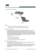
tekla tutorial lesson 6 profiles and materials
Bạn đang xem bản rút gọn của tài liệu. Xem và tải ngay bản đầy đủ của tài liệu tại đây (651.59 KB, 25 trang )
Profiles and Materials
Tekla Structures 11.0 Basic Training
March 17, 2005
Copyright © 2005 Tekla Corporation
Copyright © 2005 Tekla Corporation TEKLA STRUCTURES BASIC TRAINING
i
Contents
Contents
6 Profiles and Materials 3
6.1 Create Your Own Parametric Profile 4
6.2 Manage Library Profiles 17
6.3 Add a New Material 21
Copyright © 2005 Tekla Corporation TEKLA STRUCTURES BASIC TRAINING
3
Profiles and Materials
6 Profiles and Materials
This lesson explains how to view and modify the catalogs. You will learn how to
create a new parametric profile with the sketching tool, how to add a profile to the
library profiles and how to group library profiles with rules.
After updating the profile catalog we will use the new profile in the model to create
the crane beams.
In this lesson you will also learn how to add a new material type and a new grade to
the material catalog. We will use this new defined material for the silos in the
model.
Catalogs are databases containing detailed information about profiles, materials and
bolts, which are available for use in your project. For example, the bolt catalog
contains a library of standard bolts and bolt assemblies used in structural steelwork.
Catalogs can also contain project or company-specific information. Catalogs can
also be imported and exported.
See more in Tekla Structures
Help: System > Catalogs > Things you should know
See more for profile import and export in Tekla Structures
Help: System > Catalogs >
The profile catalog > Merging profile catalogs
.
See more about material catalogs in Tekla Structures
Help: System > Catalogs > The
material catalog.
In this lesson
Introduction
Copyright © 2005 Tekla Corporation TEKLA STRUCTURES BASIC TRAINING
4
Profiles and Materials
6.1 Create Your Own Parametric Profile
In this exercise we will define a new cross section to be used for a crane beam.
We will create the crane beam as a parametric profile using the Tekla Structures
cross section sketch editor.
Sketch a cross section
We are going to open the Cross section sketch editor and then sketch a rough outline
of the shape shown above. It doesn’t matter if the lines are exactly horizontal or
vertical, or if they touch at the ends. Neither the dimensions are important at this
stage. We will connect the ends of the poly-line and force the lines to be horizontal
or vertical later.
1. Select Sketch parametric cross section from File > Catalog > Profiles >
Sketch parametric cross section
to open the sketch editor.
The sketch editor opens showing the sketch editor view with toolbar, Variables
dialog box and Sketch browser.
Open sketch
editor
Copyright © 2005 Tekla Corporation TEKLA STRUCTURES BASIC TRAINING
5
Profiles and Materials
1. Click on the
Sketch polyline icon.
2. Sketch the profile shown below and click the middle mouse button.
The yellow circles represent "chamfers" in the sketch editor.
Sketch a cross
section
Copyright © 2005 Tekla Corporation TEKLA STRUCTURES BASIC TRAINING
6
Profiles and Materials
3. Click on the
Coincident constraint icon.
4. Pick the ends of the lines one by to connect the ends
1. Click on the
Horizontal constraint icon.
2. Select all the lines you want to be horizontal.
3. Click on the
Vertical constraint icon.
4. Select all the lines you want to be vertical.
Force the lines to
horizontal /
vertical
Copyright © 2005 Tekla Corporation TEKLA STRUCTURES BASIC TRAINING
7
Profiles and Materials
Add dimension constraints to the cross section
We will now add the needed dimension parameters to the cross section.
Some of the dimension parameters in the parametric profile (the red ones in the
figure below) will be user definable and some (the black ones) will be tied to the
user definable parameters with equations.
1. Click on the
Sketch horizontal distance icon.
2. Select 2 points (shown in red) and then the dimension line position.
A dimension is then added and a variable is added to the variables table.
3. Repeat adding dimensions for the edge fold thicknesses (b2, b3) and the web
thickness (b4).
Add horizontal
dimensions
Copyright © 2005 Tekla Corporation TEKLA STRUCTURES BASIC TRAINING
8
Profiles and Materials
4. In the variables table, change parameter b3 to be
= b2. B3 is then automatically
hidden.
5. Add a dimension b5 as shown.
Take care not to add too many dimensions to the profile or the
constraints will work against each other.
6. In the variables table, change parameter b5 to be9
7.
This will result the upper flange to be horizontally symmetrical
Copyright © 2005 Tekla Corporation TEKLA STRUCTURES BASIC TRAINING
9
Profiles and Materials
8. Add a dimension to the lower flange width and to the left cantilever.
9. Add the equation =(b6-b4)/2 to the cantilever.
This will result in the left and right cantilevers being symmetrical.
Copyright © 2005 Tekla Corporation TEKLA STRUCTURES BASIC TRAINING
10
Profiles and Materials
1. Click on the
Sketch vertical distance icon.
2. Add a dimension for the profile height.
3. Add dimensions for edge fold heights.
Add vertical
dimensions:
Copyright © 2005 Tekla Corporation TEKLA STRUCTURES BASIC TRAINING
11
Profiles and Materials
4. Add the equation h3 =h2.
5. Add dimensions for the upper flange thicknesses.
6. Add the equation h5 =h4
7. Add dimensions for the lower flange thicknesses.
Copyright © 2005 Tekla Corporation TEKLA STRUCTURES BASIC TRAINING
12
Profiles and Materials
8. Add equation h8=h7
Now the profile is symmetric.
1. Select
Show for Visibility for the variables that can be user defined. Edit the
labels of the shown parameters.
Edit the labels
Copyright © 2005 Tekla Corporation TEKLA STRUCTURES BASIC TRAINING
13
Profiles and Materials
2. Save the profile.
3. Type the prefix "CRANE" into the
User profile cross section dialog box.
4. Click
OK.
5. Close the profile.
6. Reply
No to the question about saving the sketch.
The parametric profile is now ready to be used in the profile catalog.
Modify the parametric profile – edit chamfers
We will next complete the cross section shape by modifying two inner corners of the
crane beam profile, which require a radius.
Copyright © 2005 Tekla Corporation TEKLA STRUCTURES BASIC TRAINING
14
Profiles and Materials
1. Open the component catalog (Ctrl + f) and select the category
Sketches or select
File > Catalog > Profiles > Modify sketched parametric cross section to access the
profile you created in the catalog.
2. Double-click on the sketch CRANE that you just created.
3. Add chamfers to the profile: double-click on a circle highlighted in red, select
curved chamfer type, and enter radius values as shown,
Modify.
See more about chamfers in Tekla Structures Help: Modeling > Detailing >
Detailing commands > Chamfer.
4. Repeat editing the chamfer in the other highlighted corner.
5. Close and save the sketch.
Reopen the profile
for editing
Add rounding to
the contour plate
corners
Copyright © 2005 Tekla Corporation TEKLA STRUCTURES BASIC TRAINING
15
Profiles and Materials
6. Click
Yes to update the existing profiles in the model.
1. Double-click on the
Create beam icon. Tekla Structures opens the Beam
properties
dialog.
2. Click on the
Select… button on the right side of the Profile field. The Select
profile
dialog opens.
3. Select
Parametric profile as the category and User-defined, parametric as the
profile type.
4. On the
Profile subtype list, select the CRANE profile that you just created.
5. Create a beam to the model and test the profile with different parameters.
Test the
parametric profile
Copyright © 2005 Tekla Corporation TEKLA STRUCTURES BASIC TRAINING
16
Profiles and Materials
Copyright © 2005 Tekla Corporation TEKLA STRUCTURES BASIC TRAINING
17
Profiles and Materials
6.2 Manage Library Profiles
Add an instance of a parametric profile to the profile library
In case you often need to use specific size parametric profiles, it might be a good
idea to add them as standard (fixed) profiles to the profile catalog. The dimensions
of a library profile are fixed and can be changed only in the
Modify profile catalog
dialog box.
This makes it faster and easier to select the necessary profile and also reduces the
risk of incorrect user-defined parameters.
See more information about the profile catalog in Tekla Structures help System >
Catalogs > The profile catalog.
1. Select
File > Catalog > Profiles > Modify… on the menu to open the Modify profile
catalog
dialog box.
2. Right-click in the tree structure and select
Add profile.
A new profile will be created with the name
PROFILE (number).
3. Change the profile name to
CRANE400.
4. Choose the
Profile type, User defined, parametric from pull-down list and the
Profile subtype CRANE.
5. Enter dimensions for the profile as shown below.
Add profile
Set profile
properties
Copyright © 2005 Tekla Corporation TEKLA STRUCTURES BASIC TRAINING
18
Profiles and Materials
6. Click
Update to insert the values to the profile.
You could now easily continue adding crane profiles of any other sizes
(Crane 500, Crane 600, etc.) to the library.
7. Click
OK to save the values.
8. Click
OK to Confirm the save of the profile to the model folder
The profile can now be found among the library profiles and is ready for use.
Add a rule to the profile catalog
In the profile catalog, the library profiles are grouped according to rules such as
profile type (e.g. I profiles) and profile sub-type (e.g. HEA).
We will now add a rule for the CRANE profiles in the profile catalog. See more
about rules in Tekla Structures Help: System > Catalogs > The profile catalog >
Working with rules.
1. Select
File > Catalog > Profiles > Modify… on the menu.
2. Right-click on the profile tree dialog and select
Add rule.
Add a rule
Copyright © 2005 Tekla Corporation TEKLA STRUCTURES BASIC TRAINING
19
Profiles and Materials
3. Type in the Rule name: CRANE profiles.
4. As the
Profile type, to which the rule will be applied, select All profiles.
5. As the
Name filter string, type "CRANE*".
See more about filters in Tekla Structures System > Catalogs > Things you should
know > The filter.
As a default, the wildcard symbol (*) is entered, meaning "all entries".
To group all catalog entries with names beginning with A, enter A* as
the Name filter string. To group all catalog entries with names
containing 100, enter *100*. The characters * and ? can also be used in
object names. If the object name you want to filter contains * or ?,
enclose * or ? in square brackets. E.g., to find the profile P100*10, enter
P100[*]10 in the filter field.
6. Click
OK to save the rule and close the dialog.
7. Confirm to save the profile to the model folder.
Copyright © 2005 Tekla Corporation TEKLA STRUCTURES BASIC TRAINING
20
Profiles and Materials
Use the profile in the model
1. Double-click on the
Create beam icon and select the profile CRANE400.
2. Create one crane beam from gridline 1 to 4. Start at the outer edge of the
supporting beam on gridline 1, and end at the middle of the supporting beam on
gridline 4.
3. Set the position in plane and position in depth fields to position the beam as
shown.
To get the right offset for the "on plane position", use the measuring
tool!
4. Select the crane beam and make a copy of it to go from gridline 4 to gridline 7.
5. Select both crane beams and copy them to the other side of the building on
gridline C.
Create the beams
Copyright © 2005 Tekla Corporation TEKLA STRUCTURES BASIC TRAINING
21
Profiles and Materials
We now have crane beams on both sides of the building.
6.3 Add a New Material
We will next add a new material to the Material catalog.
See more about the material catalog in Tekla Structures help System > Catalogs >
The material catalog.
Add a new material type
We will first create a new material type under which the new material will be
created.
Select
File > Catalog > Materials > Modify… on the menu to open the Modify material
catalog
dialog.
Open the material
catalog
Copyright © 2005 Tekla Corporation TEKLA STRUCTURES BASIC TRAINING
22
Profiles and Materials
If the material type you need is missing from the tree, you can create a new one.
1. Right-click on a material branch in the tree and select
Add miscellaneous branch.
Add a new material
We will next add a zero-weight material under the miscellaneous branch and use it
for the silos in the model.
2. Right-click on the
Miscellaneous branch in the tree and select Add grade.
3. Type Zero_weight for the material name in the tree.
Create a new
material type
Create a new
material grade
Copyright © 2005 Tekla Corporation TEKLA STRUCTURES BASIC TRAINING
23
Profiles and Materials
4. Add the material's density 0.00 for profiles and plates.
5. Save the new material type and grade by clicking
OK.
We will next use the new zero-weight material for the silos in order to exclude the
silos from the total weight of the model.
Select the two silos in the model and double-click on one of them while holding the
Shift button down to open the properties dialog.
1. Select
Zero_weight material from Select material list.
2. Close
Select material dialog by clicking OK.
3. Click on the
Modify button in the Column properties dialog to change the
material of the silos.
Change material
of the silos
Copyright © 2005 Tekla Corporation TEKLA STRUCTURES BASIC TRAINING
24
Profiles and Materials