tekla tutorial lesson 5 basic modeling 2 steel precast
Bạn đang xem bản rút gọn của tài liệu. Xem và tải ngay bản đầy đủ của tài liệu tại đây (1.6 MB, 49 trang )
Basic Modeling 2
Tekla Structures 12.0 Basic Training
September 20, 2006
Copyright © 2006 Tekla Corporation
Contents
Contents i
5 Basic Modeling 2 3
5.1 Start a New Model - BasicModel2 4
5.2 Setting Up Job Specific Information 7
5.3 Create Concrete Members 11
5.4 Create Steel Members 23
5.5 Combine Models 1 and 2 41
5.6 Define Your Own Select Filters 45
Copyright © 2006 Tekla Corporation TEKLA STRUCTURES BASIC TRAINING
i
Contents
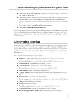
5 Basic Modeling 2
In this lesson we will cover some preliminary tasks that you need to do before starting to
model in a real project. We will create a new model and recap the basic functions introduced
in lesson 1. After that, you will learn some more about the basic functions.
You will learn how to:
In this lesson
• Set up project information
• Define part properties and numbering series
• Work in true planes (sloped, skewed)
• Use phases
• Combine separate models
• Create your own select filters
Copyright © 2006 Tekla Corporation TEKLA STRUCTURES BASIC TRAINING
3
Basic Modeling 2
5.1 Start a New Model - BasicModel2
Start a new model and name it BasicModel2.
Create new model
1. Pick the New icon.
Start a new model
2. Save in
C:\TeklaStructuresModels, type Model name "BasicModel2".
3. Click the
OK button and the model will be created.
Create grid
We will now create a grid for the model. In order to combine Basic Model 1 and Basic
Model 2 later, we will take into account the positioning of Basic Model 1 and define the
origin of Basic Model 2 grid to be 0,13900,0 in the global coordinates.
The grid is created according to the work plane, the current local coordinate system, of the
model. So before creating the grid we will temporarily position the work plane to the global
coordinates 0,13900,0.
The red coordinate arrow symbol indicates the work plane, which is the current
local coordinate system of the model. Most of the commands dependent on the
coordinate system use work plane coordinates.
You can create a skew grid by first setting the work plane to the desired skew
position.
Copyright © 2006 Tekla Corporation TEKLA STRUCTURES BASIC TRAINING
4
Basic Modeling 2
Set Work plane to
a new position
1. On the menu, select
View > Work plane > With one point.
2. Type 0,13900, click Enter or OK.
The work plane is positioned in global 0,13900,0
You can also create a grid and then move the grid with the Move command.
You can use the command Work plane > With one point to set the work plane
exactly to the desired position. This command keeps the work plane parallel to
the current work plane, but moves it to a new position using a single picked
point.
1. Delete the default grid (if there exists one).
Create the grid
2. Double-click on the
Create grid line icon.
3. Edit the grid, in the
Grid properties dialog box, according to the grids shown in the
figure above (coordinates and text).
4. Click
Create.
5. Enter GRID2 in the
Save as field and click the Save as button to save the grid values.
1. Click anywhere in the view.
Fit work area
2. Right-click and select
Fit work area.
The view should now look like the one below.
Copyright © 2006 Tekla Corporation TEKLA STRUCTURES BASIC TRAINING
5
Basic Modeling 2
Create plane views along gridlines
We will now create Elevation and Plan views along the gridlines.
1. Select the grid.
Create grid views
2. Right-click and select
Create view > Grid views from the pop-up menu.
3. Click the
Show… button on each view plane to open the View properties dialog box,
set the view properties the way you want and click
OK.
4. Click
Create in the Creation of views along grid lines dialog box.
Copyright © 2006 Tekla Corporation TEKLA STRUCTURES BASIC TRAINING
6
Basic Modeling 2
5.2 Setting Up Job Specific Information
Prior to adding any parts we will setup the model with the necessary job specific
information:
• Project properties
• Preferences
• Part properties and numbering series
Project properties
Project properties are common to all drawings and can be used to fill in typical information
in the title blocks.
1. Open the
Project properties dialog box by selecting Properties-> Project…
Set up project
properties
2. Fill in the information as shown in the dialog box below.
3. Press
OK.
Check preferences
Before starting the modeling we will check that preferences are set up correctly.
Help: System > Using Tekla Structures effectively > General > Preferences
Copyright © 2006 Tekla Corporation TEKLA STRUCTURES BASIC TRAINING
7
Basic Modeling 2
Check that your preferences are set up correctly before you start modeling. If
you change settings on the Preferences tab, Tekla Structures only applies the
new settings to connections you subsequently create. Connections you created
prior to changing the preferences are not affected.
1. Open Setup > Options…
Check
preferences
2. On the
Preferences tab check the values are as below, click OK.
Part properties and numbering series
You use a numbering series (numbering prefixes and start numbers) to divide parts,
assemblies (steel detailing) and cast units (concrete detailing) into groups. For example, you
can allocate separate numbering series to different phases or part types.
You can name the numbering series to which a part, assembly or cast unit belongs, by using
the part properties dialog box. The numbering series name consists of a prefix and a starting
number.
If you already know in the beginning of the project how the members should be numbered it
is a good idea to create the parts right from the start with the correct numbering series.
Copyright © 2006 Tekla Corporation TEKLA STRUCTURES BASIC TRAINING
8
Basic Modeling 2
Help: Modeling > Parts > Numbering parts > Defining numbers to be used for parts
In a later lesson you will learn the basics of numbering parts in Tekla Structures; how
numbering series result in different part / assembly /cast unit numbers, numbering settings
etc.
Go through each of the part properties dialog box (Beam properties, Column properties,
Contour plate properties, etc.) and set them up with the information shown in the tables
below and save each of them with a specific name. See the Adjust Beam properties example
below the tables.
Set the part
properties
Steel members
Parts/
command
Part
prefix
Part
start no.
Assembly
prefix
Assembly
start no.
Part name Material Class
Beam
command:
Beams PB 1 AB 1 BEAM S355JR 6
Vertical
braces
PV 1 AV 1 BRACING_V S355JR 3
Horizontal
braces
PH 1 AH 1 BRACING_H S355JR 3
Rafters PR 1 AR 1 RAFTER S355JR 9
Purlins PP 1 AP 1 PURLIN S355JR 8
Column
command:
Columns PC 1 AC 1 COLUMN S355JR 7
Silos PX 1 AX 1 SILO S355JR 1
Contour
plate
command:
Plates 1001 A 1 PLATE S355JR 99
Concrete members
Parts/
command
Cast unit
prefix
Cast unit
start no.
Part name Material Class
Concrete
beam
command:
Beams CB 1 BEAM K40-1 6
Hollow-core
slabs
CH 1 HCSLAB K40-1 1
Concrete
column
command:
Columns CC 1 COLUMN K40-1 3
Pad footing
command:
Pad footings CP 1 FOOTING K40-1 2
Concrete
slab
Copyright © 2006 Tekla Corporation TEKLA STRUCTURES BASIC TRAINING
9
Basic Modeling 2
command:
Slabs CS 1 SLAB K40-1 4
1. Open the Beam properties dialog.
Example: Adjust
beam properties
2. Match the highlighted fields in the dialog box below.
Type the part name
BEAM in the save as field and click the Save as button.
Save defaults
After you have set up the properties, you must save the Project properties and Preferences
for this model with the
Save defaults command.
The
Save defaults command creates a set of standard files which also include the part
properties files. These standard properties are loaded when you open the model.
In other words, when you want specific properties to be loaded by default when you open a
model, set up and load the properties before using the
Save defaults command.
Help: System > Files and Folders > Customizing Tekla Structures > Save defaults
Click Setup > Save defaults.
Save Defaults
Copyright © 2006 Tekla Corporation TEKLA STRUCTURES BASIC TRAINING
10
Basic Modeling 2
5.3 Create Concrete Members
First we will create pad footings and columns on gridline 1 and then copy them to the other
gridlines.
We will then create beams on gridlines 1 and 3 and mirror them to the other side of the
structure. With a slab generation macro, we will then create TT slabs on top of the beams at
level 7175.
Finally we will create a sloped grouting on top of the TT slabs.
Pre-cast footings
We will now create foundations on gridline 1.
1. Double-click on the
Create pad footing icon.
2700*2700 footing
Copyright © 2006 Tekla Corporation TEKLA STRUCTURES BASIC TRAINING
11
Basic Modeling 2
2. Load the saved
FOOTING properties.
3. Enter the pad footing information in the dialog box for a 2700*2700 footing as shown in
the drawing.
4. Click
Apply.
5. Pick grid intersections C-1 and F-1.
While still in the command:
2100*2100 footing
6. Enter the pad footing information in the dialog box for a 2100*2100 footing as shown in
the drawing.
7. Click
Apply.
8. Pick grid intersections D-1 and E-1.
The footings should now look like those shown below:
Pre-cast columns
Now we will create the columns on gridline 1.
1. Double-click on the
Create Concrete column icon.
900*600 columns
2. Load the
COLUMN properties that you saved earlier.
3. According to the drawing shown above, enter the information in the
Concrete column
properties
dialog box for a 900*600 column, and click Apply.
4. Pick the intersections of grids C-1 and then F-1.While still in the command:
Complete the dialog for 600*600 columns and create them on grid intersections D-1 and E-1.
600*600 columns
Copyright © 2006 Tekla Corporation TEKLA STRUCTURES BASIC TRAINING
12
Basic Modeling 2
Copy the members
We will now copy the footings and columns to other gridlines.
1.
Select the footings and columns on gridlines C and F.
Copy the
members on
gridlines C and F
2. Right-click and select
Copy > Translate… on the pop-up menu.
3. Pick two points to show the translation vector (6000 in x direction).
4. Type in the number of copies (6).
5. Click
Copy.
1. Select the footings and columns on gridlines D and E.
Copy the
members on
gridlines D and E
2. Right-click and select
Copy > Translate… on the pop-up menu.
3. Pick two points to show the translation vector (12000 in x direction).
4. Type in the number of copies (3).
5. Click
Copy.
Copyright © 2006 Tekla Corporation TEKLA STRUCTURES BASIC TRAINING
13
Basic Modeling 2
Pre-cast ledger beams
We will now create the beams on gridlines 1 and 3 at level +7175.
Copyright © 2006 Tekla Corporation TEKLA STRUCTURES BASIC TRAINING
14
Basic Modeling 2
1. Double-click on the
Create concrete beam icon.
Create beams on
gridlines 1 and 3
2. Load the
BEAM properties that you’ve saved.
3. Enter the information in the
Concrete beam properties dialog box for gridline 1 beams
according to the drawing above, click
Apply.
4. In the 3D view pick the reference point of the column at C-7175 .
5. Still having the cursor snapping to the picked point, type z to lock the z coordinate and
then pick the top point of the column at D-7175.
Copyright © 2006 Tekla Corporation TEKLA STRUCTURES BASIC TRAINING
15
Basic Modeling 2
6. End the command by clicking the middle mouse button.
7. Still having the z coordinate locked, create the other two beams on gridline 1 in the same
way.
8. Enter the information for the beams on gridline 3 in the
Concrete beam properties
dialog box, click
Apply.
9. Create the gridline 3 beams.
10. Type z to unlock the z coordinate
The model should now look as shown below.
Mirror the beams
to gridlines 5 and
7
1. Select the beams just created on gridlines 1 and 3.
2. Copy special > Mirror the beams to the other end of the structure indicating two points
on gridline 4 as the mirror line.
Copyright © 2006 Tekla Corporation TEKLA STRUCTURES BASIC TRAINING
16
Basic Modeling 2
The model now looks as shown below.
Pre-cast TT slabs
We will now create precast TT slabs on top of the framework by using the Modeling of Slab
Area
macro (88).
3. Find the
Modeling of Slab Area macro (88) in the Component catalog.
Create the TT
slabs
4. Double-click on the component to open the component dialog box.
5. Complete the dialog box as shown and
Apply.
Copyright © 2006 Tekla Corporation TEKLA STRUCTURES BASIC TRAINING
17
Basic Modeling 2
6. In the PLAN +7175 view, pick positions 1 and 2 (the intersections of gridlines and the
column edges) as shown, click the middle mouse button.
7. Pick positions 3 and 4 as shown, click the middle mouse button.
8. Pick positions 5 and 6, click the middle mouse button.
9. Then, pick position 4.
Copyright © 2006 Tekla Corporation TEKLA STRUCTURES BASIC TRAINING
18
Basic Modeling 2
The slabs are created.
10. Select the macro symbol and copy it to the other spans.
Copyright © 2006 Tekla Corporation TEKLA STRUCTURES BASIC TRAINING
19
Basic Modeling 2
Second stage concrete / grouting
We will create grouting out of four symmetrical slabs. First, we create one slab, edit the
sloping for the slab, and then copy-mirror the rest of the slabs.
Create the
grouting
1. Double-click on the
Create concrete slab icon.
2. Load the
SLAB properties that you saved earlier.
3. Set the profile to 50 and the position in depth to Front and
Apply.
4. In the PLAN +7175 view, pick the four corners for the slab as shown.
(1) Outer corner of the column
(2) Intersection of the gridline and the column edge
(3) Mid point of the gridline
(4) Outer edge of the beam (Perpendicular snap)
5. Click the middle mouse button to create the slab.
Copyright © 2006 Tekla Corporation TEKLA STRUCTURES BASIC TRAINING
20
Basic Modeling 2
We will next set the sloping for the grouting by editing the dz values of the three chamfers
shown below.
Create the rest of
the slabs
1. Create the rest of the slabs (with Copy-Translate).
Copyright © 2006 Tekla Corporation TEKLA STRUCTURES BASIC TRAINING
21
Basic Modeling 2
Set the sloping for
the grouting
2. Double-click on the chamfer.
3. Set the Dz1 value to 150,
Modify.
4. Repeat this for the other two chamfers.
Copyright © 2006 Tekla Corporation TEKLA STRUCTURES BASIC TRAINING
22
Basic Modeling 2
5.4 Create Steel Members
First, we will create two columns on gridline 1 and then a rafter between them.
After that we will create the construction points needed to create the horizontal bracing and
purlins. We will copy-translate the completed portal frame and points.
We will then replace the concrete columns on gridlines 2, 4 and 6, combining them with the
upper steel columns so that they are turned into full-length steel columns.
Utilizing a sloping work plane and view planes, we will model the horizontal bracing and
purlins.
Finally, we will create vertical bracing on gridlines C and F.
Steel columns
We first create two columns on gridline 1.
1. Double-click on the
Create column icon.
Create columns
2. Load the
COLUMN properties.
Copyright © 2006 Tekla Corporation TEKLA STRUCTURES BASIC TRAINING
23
Basic Modeling 2