bs 5306-2-1990 fire extinguishing installations and equipment on premises
Bạn đang xem bản rút gọn của tài liệu. Xem và tải ngay bản đầy đủ của tài liệu tại đây (3.44 MB, 170 trang )
BRITISH STANDARD
BS5306-2:
1990
Incorporating
Amendment No.1 and
implementing
Corrigendum No.1
Fire extinguishing
installations and
equipment on
premises—
Part2: Specification for sprinkler
systems
ICS13.220.10
Licensed copy:RMJM, 30/08/2005, Uncontrolled Copy, © BSI
BS5306-2:1990
This British Standard, having
been prepared under the
directionof the Fire Standards
Policy Committee, was
publishedunder the authority
ofthe Board of BSI and
comesintoeffect on
31 July1990
© BSI05-1999
First published (as CP402, 201)
April1952
Second edition (as BS5306-2)
June1979
Third edition July1990
The following BSI references
relate to the work on this
standard:
Committee reference FSM/3
Draft for comment88/41076DC
ISBN 0 580 18560 5
Committees responsible for this
British Standard
The preparation of this British Standard was entrusted by the Fire Standards
Policy Committee (FSM/-) to Technical Committee FSM/13, upon which the
following bodies were represented:
Association of Metropolitan Authorities
British Automatic Sprinkler Association
British Fire Protection Systems Association Ltd.
British Fire Services’ Association
British Nuclear Fuels Ltd.
Chief and Assistant Chief Fire Officers’ Association
Convention of Scottish Local Authorities
Department of Health
Department of the Environment (Property Services Agency)
Department of the Environment (Building Research Establishment)
Department of Transport (Marine Directorate)
Electricity Supply Industry in England and Wales
Engineering Equipment and Materials Users’ Association
Fire Brigades Union
Fire Extinguishing Trades’ Association
Health and Safety Executive
Hevac Association
Home Office
Incorporated Association of Architects and Surveyors
Institution of Fire Engineers
Lloyds Syndicates Survey Department
London Fire and Civil Defence Authority
Loss Prevention Council
Ministry of Defence
Royal Institute of British Architects
Society of Fire Protection Engineers
Society of Motor Manufacturers and Traders Ltd.
United Kingdom Atomic Energy Authority
Warrington Fire Research Centre
Water Research Centre
The following bodies were also represented in the drafting of the standard,
through subcommittees and panels:
Copper Development Association
London District Surveyors Association
Amendments issued since publication
Amd. No. Date of issue Comments
9809 January1998
9985
CorrNo.1
April1998 Indicated by a sideline in the margin
Licensed copy:RMJM, 30/08/2005, Uncontrolled Copy, © BSI
BS5306-2:1990
© BSI 05-1999
i
Contents
Page
Committees responsible Inside front cover
Foreword vii
Section 1. General
0 Introduction 1
1 Scope 2
2 Definitions 2
Section 2. Planning
3 Initial considerations 9
4 Extent of sprinkler protection 10
5 Classification of occupancies and fire hazards 11
6 Selection of installation type, size and design 18
7 Hazard to personnel 22
Section 3. Contract arrangements
8 Contract drawings/information documents 24
9 Work on site 28
10 Commissioning and acceptance tests 28
11 Extension and alteration of sprinkler systems 30
Section 4. Water supplies
12 General 32
13 Types of water supply 32
14 Design density and AMAO for fully hydraulically
calculated installations 44
15 Water supply pressure-flow characteristics and velocity 48
16 Water storage capacity 52
17 Town mains, elevated private reservoirs, gravity tanks,
suction and booster pumps, and pressure tanks 52
18 Hydraulic calculation and pipe sizing tables 74
19 Pressure-flow tests on water supplies 77
Section 5. Components and installation design
20 Valves 79
21 Pipe and pipe fittings 84
22 Pipework supports 87
23 Pipework in cold-storage warehouses 92
24 Pipe sizing and sprinkler array design 92
25 Sprinkler, multiple control and sprayer design
characteristics and uses 108
26 Sprinkler spacing, arrangement and location 113
27 Alarms and alarm devices 132
28 Pressure gauges 136
Section 6. Signs, notices, information and colour coding
29 Block plan 137
30 Signs and notices 137
31 Marking and colour coding 137
Section 7. Upkeep of the system
32 General arrangements 140
33 Action following sprinkler operation 141
34 User’s programme of inspection and checking 142
35 Service and maintenance schedule 143
Licensed copy:RMJM, 30/08/2005, Uncontrolled Copy, © BSI
BS5306-2:1990
ii
© BSI 05-1999
Page
Appendix A Water supply pressure test 146
Appendix B Orifice plate design 146
Appendix C Precautions when carrying out hot work 147
Figure 1 — Main elements of a sprinkler installation 1
Figure 2 — Examples of range pipe arrays 4
Figure 3 — Hazard classification flow chart 15
Figure 4 — Typical statement of pressure loss calculations 27
Figure 5 — Typical pump data sheet 29
Figure 6 — Typical completion certificate and test data sheet 31
Figure 7 — Superior supply using town main 34
Figure 8 — Superior supply using elevated private reservoir 34
Figure 9 — Superior supply using gravity tank 35
Figure 10 — Superior supply using suction pumps 36
Figure 11 — Superior supply using pressure tank 37
Figure 12 — Duplicate supplies using two town mains 38
Figure 13 — Duplicate supplies using town main and pressure tank 38
Figure 14 — Duplicate supplies using selection from suction
pump/pressure tank/gravity tank 39
Figure 15 — Duplicate supplies using two gravity tanks 40
Figure 16 — Duplicate supplies using a private reservoir
and a pressure tank 41
Figure 17 — Duplicate supplies using two suction pumps from
riverorcanal(suction lift condition) 42
Figure 18 — Duplicate water supplies using two suction pumps
fromalimitedcapacity tank and a full capacity tank 43
Figure 19 — Examples of precalculated mixed ordinary and
high-hazard installations 51
Figure 20 — Typical installer’s pump data sheet 61
Figure 21 — Measurement of positive suction head 61
Figure 22 — Measurement of negative suction head 62
Figure 23 — Effective capacity of suction tanks 63
Figure 24 — Jackwells or suction pits 67
Figure 25 — Alarm valve and bypass arrangement
for life safety installations 80
Figure 26 — Duplicate alarm valve arrangement for life
safety installations 81
Figure 27 — Some common types of pipe hanger equipment 88
Figure 28 — Example of application of design points in a
light-hazard installation 95
Figure 29 — Example of application of design points in
an ordinary-hazard installation 97
Figure 30 — Example of application of design points in a high-hazard
installation with pipework sized from Table 60 and Table 62 98
Figure 31 — Example of application of design points in a high-hazard
installation with pipework sized from Table 60 and Table 63 99
Figure 32 — Example of application of design points in a high-hazard
installation with pipework sized from Table 62 100
Figure 33 — Area covered by individual sprinklers where less
thanfoursprinklers are in open communication 104
Figure 34 — Area covered by individual sprinklers (large arrays) 107
Licensed copy:RMJM, 30/08/2005, Uncontrolled Copy, © BSI
BS5306-2:1990
© BSI 05-1999
iii
Page
Figure 35 — Typical hydraulically most favourable/unfavourable
locationsofAMAO in an installation with terminal main
distribution piping 109
Figure 36 — Typical hydraulically most favourable/unfavourable
locationsofAMAO in an installation with looped distribution piping 109
Figure 37 — Typical hydraulically most favourable/unfavourable
locationsofAMAO in an installation with gridded piping 110
Figure 38 — Ceiling sprinkler spacing 116
Figure 39 — Sidewall sprinkler spacing 117
Figure 40 — Terminology for type S5 storage (beam pallet racking) 119
Figure 41 — Sprinkler locations for type S5 storage,
categoryI orII goods (beam pallet racking) 120
Figure 42 — Sprinkler locations for type S5 storage,
categoryIII goods (beam pallet racking) 121
Figure 43 — Sprinkler locations for type S5 storage,
categoryIV goods (beam pallet racking) 122
Figure 44 — Sprinkler locations for type S7 storage (shelved racks) 123
Figure 45 — Sprinkler locations for type S9 storage (potable
spirits in barrels in double racks with aisles and walkways) 124
Figure 46 — Sprinkler locations for type S10 storage (potable
spirits in barrels in racks with aisles and walkways) 125
Figure 47 — Sprinkler location relative to beams 128
Figure 48 — Protection of tiered conical plant, e.g.cyclone
dust collectors 130
Figure 49 — Typical installation notice for fully hydraulically
designed pipework 138
Figure 50 — Typical hot work permit 149
Table 1 — Classification of stacked goods and limitations on
storage methods 13
Table 2 — High-piled storage hazards showing typical examples
in goods categories 14
Table 3 — Typical examples of ordinary-hazard occupancies 16
Table 4 — Process high hazards showing examples of types 17
Table 5 — Connections for water for other services in low-rise systems 33
Table 6 — Combinations suitable for duplicate water supplies 37
Table 7 — Minimum design density and AMAO for light-ordinary- and
high-hazard (processes) roof or ceiling sprinklers 44
Table 8 — Minimum design density and AMAO for high-piled storage
hazards(goods), storage types S1 and S4 roof or ceiling sprinklers 45
Table 9 — Minimum design density and AMAO for high-piled storage
hazards(goods), storage types S2 and S5, roof or ceiling sprinklers 45
Table 10 — Minimum design density and AMAO for high-piled
storagehazards(goods), storage types S3, S6, S7 and S8, roof
or ceiling sprinklers 46
Table 11 — Minimum design density and AMAO for high-piled storage
hazards(goods), top tier protection by roof or ceiling sprinklers only 46
Table 12 — Minimum design density and AMAO for bonded spirit
stores,typeS8, roof or ceiling sprinklers 47
Table 13 — Number of sprinklers per row, and number of tiers per
rack,assumedto be in simultaneous operation 47
Licensed copy:RMJM, 30/08/2005, Uncontrolled Copy, © BSI
BS5306-2:1990
iv
© BSI 05-1999
Page
Table 14 — Number of racks, walkways or ranges and of total
rowsatalevelinsimultaneous operation 48
Table 15 — Pressure and flow requirements for
ordinary-hazard installations 48
Table 16 — Pressure and flow requirements for high-hazard
installations,with15mm sprinklers (precalculated), and pipe
sizes from Table 60 and Table 62 49
Table 17 — Pressure and flow requirements for high-hazard
installations,with15mm sprinklers (precalculated), and
pipe sizes from Table 60 and Table 63 50
Table 18 — Pressure and flow requirements for high-hazard
installations,with15mm sprinklers (precalculated), and
pipe sizes from Table 61 and Table 63 50
Table 19 — Pressure and flow requirements for high-hazard
installations,with20mm sprinklers (precalculated), and pipe
sizes from Table 61 and Table 63 50
Table 20 — Water source and design capacity 53
Table 21 — Design capacity, where tank is not dependent on
inflow, for light-hazard precalculated installations 54
Table 22 — Design capacity, where tank is not dependent on
inflow, for ordinary-hazard precalculated installations 54
Table 23 — Design capacity, where tank is not dependent
on inflow, for high-hazard precalculated installations 54
Table 24 — Design capacity, where tank is not dependent on
inflow, for fully hydraulically calculated installations 54
Table 25 — Design capacity, where tank is dependent on
inflow at refilling rate f, L/min 54
Table 26 — Pump pressure, flow and speed rating 56
Table 27 — Pump maximum power absorption for driver sizing 59
Table 28 — Pump pressure and flow for light- and ordinary-hazard
(precalculated) installations 60
Table 29 — Suction pipe size: positive suction head condition 62
Table 30 — Suction pipe size: suction lift condition 64
Table 31 — Pump priming tank capacity and pipe size 64
Table 32 — Suction pipe inlet clearances 65
Table 33 — Minimum width of settling chambers, suction pits,
openchannelsand weirs for various water depths 66
Table 34 — Minimum pressure at highest sprinkler when pressure
tankjustempties (precalculated installations) 73
Table 35 — Pressure tank minimum air pressures (P
f
=0.3bar)
(precalculatedinstallations) 73
Table 36 — Mean size and values of “k” of various pipes 75
Table 37 — Equivalent length of fittings and valves 76
Table 38 — BS specifications and size ranges for stop, test, drain
andflushingvalves 80
Table 39 — Minimum size of drain valves and pipe 82
Table 40 — BS specifications and size ranges for check valves 83
Table 41 — BS specifications and pipe and fittings 85
Table 42 — Installation pipework slope to drain 86
Table 43 — Length of welded outlets 87
Table 44 — Test loads for support assemblies 89
Licensed copy:RMJM, 30/08/2005, Uncontrolled Copy, © BSI
BS5306-2:1990
© BSI 05-1999
v
Page
Table 45 — Minimum dimensions of pipe clips 90
Table 46 — Sling rods and “U” bolts 90
Table 47 — Coach screw, coach bolt and bolt fasteners 90
Table 48 — Drill or non-drill fasteners in concrete, brickwork
or blockwork: drill or non-drill anchor minimum diameters 90
Table 49 — On-site test loads for fasteners 90
Table 50 — Maximum distance between pipe supports 91
Table 51 — Location of sprinklers alongside feed pipes larger
than65mmnominal size 93
Table 52 — Orifice plate thickness according to pipe nominal bore 93
Table 53 — Sprinkler protection of concealed spaces 94
Table 54 — Light-hazard range pipe and terminal distribution pipe sizes 96
Table 55 — Maximum pipe flow loss between installation control valve
setandeach design point in light-hazard installations 96
Table 56 — Pressure loss per unit length of pipe for design flow
rates in light-hazard installations 96
Table 57 — Range pipe nominal sizes for various pipe layouts in
ordinary-hazard installations 101
Table 58 — Distribution pipe nominal sizes in ordinary-hazard
installations, and maximum numbers of sprinklers downstream
of design point 101
Table 59 — Pressure loss per unit length of pipe for design flow
rates in ordinary-hazard installations 101
Table 60 — Range pipe nominal sizes for various pipe layouts,
for high-hazard installations with sprinklers of15mm nominal
size and pressure-flow characteristics as given in Table 16 or Table 17 102
Table 61 — Range pipe nominal sizes for various pipe layouts,
in high-hazard installations with sprinklers of15mm nominal size
andpressure-flow characteristics as given in Table 18, or
of20mmnominalsizeand pressure-flow characteristics as
given in Table 19 103
Table 62 — Distribution pipe nominal sizes feeding various
numbersofsprinklers downstream of the design point, in high-hazard
installations with sprinklers of15mm nominal size and pressure-flow
characteristics as given in Table 16 103
Table 63 — Distribution pipe nominal sizes feeding various numbers
ofsprinklers downstream of the design point in high-hazard
installationswithsprinklers of15mm nominal size and pressure-flow
characteristics asgiven in Table 17 or Table 18, or sprinklers of20mm
nominalsize andpressure-flow characteristics as given in Table 19 103
Table 64 — Pressure loss per unit length of pipe for design flow
rates in high-hazard installations 105
Table 65 — Minimum sprinkler discharge pressure for non-rack
sprinklers in fully hydraulically calculated installations 105
Table 66 — Sprinkler types and sizes for various hazard classes 111
Table 67 — Fusible link sprinkler temperature ratings and colour code 111
Table 68 — Glass bulb sprinkler temperature ratings and colour code 111
Table 69 — Sprinkler nominal threads, orifice sizes and k factors 112
Table 70 — Maximum coverage and maximum spacing for
non-sidewall sprinklers 114
Table 71 — Maximum coverage and maximum spacing for
sidewall sprinklers 115
Licensed copy:RMJM, 30/08/2005, Uncontrolled Copy, © BSI
BS5306-2:1990
vi
© BSI 05-1999
Page
Table 72 — Location of intermediate sprinklers in type S5
storage(beampalletracking) 115
Table 73 — Location of intermediate sprinklers in type S7
storage(shelvedracks) 122
Table 74 — Maximum nearest distance of sprinklers in standard
layout from a boundary perpendicular or parallel to range lines 126
Table 75 — Maximum nearest distance of sprinklers in a
staggered layout from a boundary perpendicular or parallel
to range lines 126
Table 76 — Maximum distance of non-sidewall sprinkler
deflector below roof or ceiling 127
Table 77 — Sprinkler location relative to beams and joists 127
Table 78 — Minimum distance of sidewall sprinklers from beams
underflatceilings 128
Table 79 — Orifice plates for50mm and65mm medium grade
pipescomplyingwith BS1387 146
Table 80 — Orifice plates for80,100,150 and200mm medium
gradepipescomplying with BS1387 147
Publications referred to 155
Licensed copy:RMJM, 30/08/2005, Uncontrolled Copy, © BSI
BS5306-2:1990
© BSI 05-1999
vii
Foreword
This Part of BS5306 is published under the direction of the Fire Standards Policy
Committee. It is a revision of BS5306-2:1979 which is superseded and
withdrawn.
The other Parts of BS5306 in preparation or published are as follows:
— Part0: Guide for the selection of installed systems and other fire equipment;
— Part1: Hydrant systems, hose reels and foam inlets;
— Part3: Code of practice for selection, installation and maintenance of
portable fire extinguishers;
— Part4: Specification for carbon dioxide systems;
— Part5: Halon systems;
— Section5.1: Halon1301 total flooding systems
1)
;
— Section5.2: Halon1211 total flooding systems;
— Part6: Foam systems — Section6.1: Specification for low expansion foam
systems;
— Section6.2: Specification for medium and high expansion foam systems;
— Part7: Specification for powder systems.
The foreword of the previous edition of this Part of this standard pointed out that
it should be read in conjunction with the “Rules for automatic sprinkler
installations” (29th edition), issued by the Fire Offices Committee (FOC) now
incorporated in the Loss Prevention Council (LPC), and used by the majority of
insurers in the UK.
With the agreement and active cooperation of the LPC, this revision, initially
prepared by a consultant funded by the Department of Trade and Industry under
the BSI/DTI consultancy scheme for Initial Draft Standards, includes all matters
previously dealt with by reference to the FOC Rules.
Full acknowledgment is given to the LPC for its agreement to incorporate
material from the FOC rules, and also texts of amendments to the FOC Rules as
yet unpublished, in this new edition of this Part of this British Standard.
It is the intention of the LPC to replace the29th edition of the FOC Rules by new
document “LPC Rules for Automatic Sprinkler Installations”.
That new document will incorporate the full text of this British Standard
specification and include additional material not suitable for inclusion in a
British Standard, related to the use of sprinkler systems installed primarily to
reduce loss of property by fire. It will be available from:
Loss Prevention Council
140Aldersgate Street
London
EC1A4HX
Arrangements have been made for the continual review of this specification and
the “LPC Rules for Automatic Sprinkler Installations” to ensure that, as far as
possible, amendments to the two documents are made simultaneously so that
they remain compatible. In consequence this standard will be reviewed on an
annual basis, more frequently than is usual for most other standards. In
particular it is intended as part of the first review to consider some proposals,
made as part of the public comment, related to applications of sprinkler systems
in multi-storey buildings which merit issue for public comment. However, some
new requirements and recommendations are included covering the installation of
sprinkler systems in high-rise buildings.
1)
Under revision.
Licensed copy:RMJM, 30/08/2005, Uncontrolled Copy, © BSI
BS5306-2:1990
viii
© BSI 05-1999
There is increasing use of sprinkler systems which, in addition to protecting
property, may serve for the protection of life, usually as an integral part of
measures approved by a fire authority. An example is in covered and enclosed
shopping centres, where automatic sprinkler systems can serve to prevent the
spread of fire and its products to adjacent exit routes. This revision includes new
recommendations together with those previously given in BS5306-1:1979 in an
appendix, to ensure that the reliability of such a sprinkler system is consistent
with its function as an essential life safety measure, in such particular
circumstances or where sprinkler systems may be called for in BS5588-10
2)
.
Although sprinkler systems are likely to provide some life safety protection to
occupants of the areas of buildings in which sprinklers are installed, additional
requirements may be necessary for systems specifically intended for life safety
protection, e.g.where smoke could accumulate so rapidly that the lives of some of
the occupants might be endangered before they could escape. It is intended to
cover this subject, which may include additional recommendations for sprinkler
sensitivity for life safety purposes, in a future revision of this specification.
Emphasis is given to the importance of ensuring that components of sprinkler
systems are of established reliability and durability and suitable for the
particular application and circumstances.
The requirements and recommendations are made in the light of the best
technical data known to the committee at the time of writing, but since a wide
field is covered it has been impracticable to consider every possible factor or
circumstance that might affect implementation of the recommendations.
The previous edition of this standard was written in the form of a code of practice,
but this revision is written as a specification to make it more suitable for
reference in designs and specifications for actual projects. To comply with this
specification, the user has to comply with all its requirements. He may depart
from recommendations, but this would be on his own responsibility and he would
be expected to have good reasons for doing so. It is a requirement of this
specification to have consulted the various authorities concerned with the system,
a procedure which allows for discussion and agreement of which
recommendations may be appropriate in any particular case.
It has been assumed in the preparation of this standard that the execution of its
provisions is entrusted to appropriately qualified and experienced people.
A British Standard does not purport to include all the necessary provisions of a
contract. Users of British Standards are responsible for their correct application.
Compliance with a British Standard does not of itself confer immunity
from legal obligations. In particular, attention is drawn to:
Health & Safety at Work etc.Act1974
Water Acts1989
Water (Scotland) Acts1946/67
Water Supplies and Sewerage Act (Northern Ireland)1945
Public Health Acts (Northern Ireland)1878–1955
2)
Under revision.
Licensed copy:RMJM, 30/08/2005, Uncontrolled Copy, © BSI
BS5306-2:1990
© BSI 05-1999
ix
Product Certification. Users of this British Standard are advised to consider the
desirability of independent certification of product conformity with this British
Standard based on testing and continuing surveillance, which may be coupled
with assessment of a supplier’s quality systems against the appropriate Part of
BS5750.
Summary of pages
This document comprises a front cover, an inside front cover, pagesi tox,
pages1to156, an inside back cover and a back cover.
This standard has been updated (see copyright date) and may have had
amendments incorporated. This will be indicated in the amendment table on the
inside front cover.
Licensed copy:RMJM, 30/08/2005, Uncontrolled Copy, © BSI
x
blank
Licensed copy:RMJM, 30/08/2005, Uncontrolled Copy, © BSI
BS5306-2:1990
© BSI 05-1999
1
Section 1. General
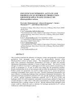
0 Introduction
A sprinkler system consists of a water supply (or
supplies) and one or more sprinkler installations;
each installation consists of a set of installation
main control valves and a pipe array fitted with
sprinkler heads. The sprinkler heads are fitted at
specified locations at the roof or ceiling, and where
necessary between racks, below shelves, and in
ovens or stoves. The main elements of a typical
installation are shown in Figure 1.
The sprinklers operate at predetermined
temperatures to discharge water over the affected
part of the area below, the flow of water through the
alarm valve initiating a fire alarm. The operating
temperature is generally selected to suit ambient
temperature conditions.
Only sprinklers in the vicinity of the fire, i.e.those
which become sufficiently heated, operate.
In some life safety applications an authority may
require sprinkler protection only in certain
designated areas and solely to maintain safe
conditions for the evacuation of persons from the
sprinklers protected areas. Such a system may not
provide protection against a fire which starts in a
non-sprinklered part of the premises and develops
to some size before spreading to the sprinkled parts,
and for more complete protection the sprinkler
system is extended throughout the premises with
only limited exceptions.
It should not be assumed that the provision of a
sprinkler system entirely obviates the need for other
means of fighting fires and it is important to
consider the fire precautions in the premises as a
whole.
Figure 1 — Main elements of a sprinkler installation
Licensed copy:RMJM, 30/08/2005, Uncontrolled Copy, © BSI
BS5306-2:1990
2
© BSI 05-1999
Structural fire resistance, escape routes, fire alarm
systems, particular hazards needing other fire
protection methods, provision of hose reels and fire
hydrants and portable fire extinguishers, etc.,safe
working and goods handling methods, management
supervision and good housekeeping all need
consideration. Advice on these matters may be
obtained from the fire authority, the Health and
Safety Executive or other enforcing authority under
the Health and Safety at Work etc.Act1974, and
the fire insurers. In addition, reference should be
made to BS5306-0 and as necessary to other Parts
of this standard.
It is essential that sprinkler systems should be
properly maintained to ensure operation when
required. This routine is liable to be overlooked or
given insufficient attention by supervisors. It is,
however, neglected at peril to the lives of occupants
of the premises and at the risk of crippling financial
loss. The importance of proper maintenance cannot
be too highly emphasized.
When sprinkler systems are disabled, extra
attention should be paid to fire precautions and the
appropriate authorities informed. Advice on fire
precautions is given in Appendix C, and is
particularly appropriate when hot work is being
carried out on a sprinkler system which in
consequence is not operational.
1 Scope
This Part of BS5306 specifies requirements and
gives recommendations for the design, installation
and maintenance of fire sprinkler systems in
buildings and industrial plant. It includes
particular requirements for sprinkler systems
which are integral to measures for the protection of
life.
It covers the classification of hazards; provision of
water supplies; components to be used; installation
and testing of the system; maintenance; and the
extension of existing systems; and identifies
construction details of buildings which are
necessary for satisfactory performance of sprinkler
systems complying with this specification.
NOTE 1This standard does not deal with water spray deluge
systems in detail.
NOTE 2Unless otherwise stated in this standard all pressures
are gauge pressures and are expressed in bars.
1bar=10
5
N/m
2
=10
2
kPa.
NOTE 3The titles of publications referred to in this standard
are listed on page155.
2 Definitions
For the purposes of this Part of BS5306 the
following definitions apply.
2.1
accelerator
a device that reduces the delay in operation of a dry
alarm valve, or composite alarm valve in dry mode,
by early detection of the drop in air pressure when a
sprinkler operates
2.2
alarm test valve
a valve through which water may be drawn to test
the operation of the water motor fire alarm and/or of
any associated electric fire alarm
2.3
alarm valve
a check valve, of the wet, dry or composite type, that
also initiates the water motor fire alarm when the
sprinkler installation operates
2.4
alarm valve, composite
an alarm valve suitable for a wet, dry or alternate
installation
2.5
alarm valve, dry
an alarm valve suitable for a dry installation; and/or
in association with a wet alarm valve for an
alternate installation
2.6
alarm valve, pre-action
an alarm valve suitable for a pre-action installation
2.7
alarm valve, recycling
an alarm valve suitable for a recycling installation
2.8
alarm valve, wet
an alarm valve suitable for a wet installation
2.9
arm pipe
a pipe, other than the last section of a range pipe,
feeding a single sprinkler
2.10
assumed maximum area of operation (AMAO)
the maximum area over which it is assumed, for
design purposes, that sprinklers will operate in a
fire
Licensed copy:RMJM, 30/08/2005, Uncontrolled Copy, © BSI
BS5306-2:1990
© BSI 05-1999
3
2.11
assumed maximum area of operation,
hydraulically most favourable location
the location in a sprinkler array of an AMAO of
specified shape at which the water flow is the
maximum for a specific pressure
2.12
assumed maximum area of operation,
hydraulically most unfavourable location
the location in a sprinkler array of an AMAO of
specified shape at which the water supply pressure
is the maximum needed to give the specified design
density
2.13
authority
an organization, officer or individual responsible for
approving sprinkler systems, equipment and
procedures (see3.1)
2.14
booster pump
an automatic pump supplying water to a sprinkler
system from an elevated private reservoir or a town
main
2.15
competent person
a person with the necessary training and
experience, and with access to the requisite tools,
equipment and information, accepted by the
authorities as capable of carrying out installation,
inspection and maintenance procedures
2.16
cut-off sprinkler
a sprinkler protecting a door or window between two
areas only one of which is protected by sprinklers
2.17
deluge installation
an installation or tail-end extension fitted with open
sprayers and either a deluge valve or a multiple
control arrangement so that an entire area is
sprayed with water on operation of the installation
2.18
deluge valve
a valve suitable for use in a deluge installation
NOTEThe valve is operated manually and usually also
automatically by a fire detection system.
2.19 design density
the minimum density of discharge, in mm/min of
water, for which a sprinkler installation is designed,
determined from the discharge of a specified group
of sprinklers, in L/min, divided by the area covered,
in m
2
2.20
design point
a point on a distribution pipe of a precalculated
installation, downstream of which pipework is sized
from tables and upstream of which pipework is sized
by hydraulic calculation
2.21
detector sprinkler
a sealed sprinkler mounted on a pressurized
pipeline used to control a deluge valve. Operation of
the detector sprinkler causes loss of air pressure to
open the valve
2.22
distribution pipe
a pipe feeding either a range pipe directly or a single
sprinkler on a non-terminal range pipe more
than300mm long
2.23
distribution pipe spur
a distribution pipe from a main distribution pipe, to
a terminal branched pipe array (see Figure 30)
2.24
drencher
a sprayer used to distribute water over a surface to
provide protection against fire exposure
2.25
drop
a vertical pipe feeding a distribution or range pipe
2.26
end-centre array
a pipe array with range pipes on both sides of a
distribution pipe (see Figure 2)
2.27
end-side array
a pipe array with range pipes on one side only of a
distribution pipe (see Figure 2)
2.28
exhauster
a device to exhaust the air from a dry or alternate
installation to atmosphere on sprinkler operation to
give more rapid operation of the alarm valve
2.29
fastener
a device for attaching pipe hanger components to a
building structure or racking
Licensed copy:RMJM, 30/08/2005, Uncontrolled Copy, © BSI
BS5306-2:1990
4
© BSI 05-1999
2.30
fire door
a door and frame of specified fire resistance
complying with either:
a) BS476-8:1972; or
b) BS476-22:1987
with respect to integrity
2.31
fire resistance
the ability of a component or the construction of a
building to satisfy for a stated period of time the
appropriate criteria specified in the relevant part of
BS476
Figure 2 — Examples of range pipe arrays
Licensed copy:RMJM, 30/08/2005, Uncontrolled Copy, © BSI
BS5306-2:1990
© BSI 05-1999
5
2.32
fire shutter
a shutter and frame of specified fire resistance
complying with either:
a) BS476-8:1972; or
b) BS476-22:1987;
with respect to integrity
2.33
(fully) hydraulically calculated
a term applied to pipework sized as specified
in18.1 a) or an installation in which all the
pipework downstream of the main installation
control valve set is sized as specified in18.1 a)
2.34
gridded configuration pipe array
a pipe array in which water flows to each sprinkler
by more than one route (see Figure 37)
2.35
hanger
an assembly for suspending pipework from
elements of building structure
2.36
high-rise system
a sprinkler system in which the highest sprinkler is
more than45m above the lowest sprinkler or the
sprinkler pumps whichever is the lower
2.37
hydraulic alarm, intermittent
sounding of an hydraulic water motor alarm gong
for intervals totalling less than the alarm period
2.38
installation (sprinkler installation)
part of a sprinkler system comprising a set of
installation main control valves, the associated
downstream pipes and sprinklers
2.39
installation, alternate
an installation in which the pipework is selectively
charged with either water or air according to
ambient temperature conditions
2.40
installation, dry (pipe)
an installation in which the pipework is charged
with air under pressure
2.41
installation, pre-action
dry or alternate in dry mode, installation in which
the alarm valve can be opened by an independent
fire detection system in the protected area
2.42
installation, recycling
a pre-action installation in which the alarm valve
can be opened and closed repeatedly by a heat
detection system
2.43
installation, wet (pipe)
an installation in which the pipework is always
charged with water
2.44
jockey pump
a small pump used to replenish minor water loss, to
avoid starting an automatic suction or booster pump
unnecessarily
2.45
life safety
a term applied to sprinkler systems forming an
integral part of measures required for the protection
of life
2.46
looped configuration
a pipe array in which there is more than one
distribution pipe route along which water may flow
to a range pipe (see Figure 36)
2.47
low-rise system
sprinkler system in which the highest sprinkler is
not more than45m above the lowest sprinkler or
the sprinkler pumps whichever is the lower
2.48
main distribution pipe
a pipe feeding a distribution pipe (see Figure 1)
2.49
mechanical pipe joint
a component part of pipework other than threaded
tubulars, screwed fittings, lead or compound sealed
spigots and socket and flanged joint, used to connect
pipes and to produce a seal both against pressure
and vacuum
2.50
multiple control
a valve, normally held closed by a
temperature-sensitive element, suitable for use in a
deluge system or for the operation of a pressure
switch
2.51
node
a point in pipework at which pressure and flow(s)
are calculated; each node is a datum point for the
purpose of hydraulic calculations in the installation
Licensed copy:RMJM, 30/08/2005, Uncontrolled Copy, © BSI
BS5306-2:1990
6
© BSI 05-1999
2.52
pipe array
the pipes feeding a group of sprinklers
NOTEPipe arrays may be looped (see2.46), gridded (see2.34)
or branched (see Figure 35).
2.53
precalculated
a term applied to pipework sized as specified
in18.1 b) or an installation in which pipes
downstream of the design point are sized as
specified in18.1 b)
2.54
range pipe
a pipe feeding sprinklers directly or via arm pipes of
restricted length
2.55
riser
a vertical pipe feeding a distribution or range pipe
above
2.56
rosette (sprinkler rosette)
a plate covering the gap between the shank or body
of a sprinkler projecting through a suspended
ceiling, and the ceiling
2.57
section
that part (which may be one or more zones) of an
installation on a particular floor fed by a particular
riser
2.58
sling rod
a rod with a sling eye or screwed ends for supporting
pipe clips, rings, band hanger etc.
2.59
sprayer
a sprinkler that gives a downward conical pattern
discharge
2.60
sprayer, high velocity
an open nozzle used to extinguish fires of high
flashpoint liquids
2.61
sprayer, medium velocity
a sprayer of sealed or open type used to control fires
of lower flashpoint liquids and gases or to cool
surfaces
2.62
sprinkler, (automatic)
a temperature-sensitive sealing device which opens
to discharge water for fire extinguishing
NOTEThe term “automatic sprinkler” is now rarely used. The
term “sprinkler” does not include “open sprinkler” (see2.72).
2.63
sprinkler, ceiling or flush pattern
a pendent sprinkler for fitting partly above but with
the temperature-sensitive element below, the lower
plane of the ceiling
2.64
sprinkler, concealed
a recessed sprinkler with a cover plate that
disengages when heat is applied
2.65
sprinkler, conventional pattern
a sprinkler that gives a spherical pattern of water
discharge
See also:
cut-off sprinkler(2.16);
detector sprinkler(2.21).
2.66
sprinkler, dry pendent pattern
a unit comprising a sprinkler and a dry drop pipe
unit with a valve, at the head of the pipe, held closed
by a device maintained in position by the sprinkler
head valve
2.67
sprinkler, dry upright pattern
a unit comprising a sprinkler and dry rise pipe unit
with a valve, at the base of the pipe, held closed by
a device maintained in position by the sprinkler
head valve
2.68
sprinkler, fusible link
a sprinkler which opens when a component provided
for the purpose melts
2.69
sprinkler, glass bulb
a sprinkler which opens when a liquid-filled glass
bulb bursts
2.70
sprinkler, horizontal
a sprinkler in which the nozzle directs water
horizontally
2.71
sprinkler, intermediate
a sprinkler installed below, and additional to the
roof or ceiling sprinklers
Licensed copy:RMJM, 30/08/2005, Uncontrolled Copy, © BSI
BS5306-2:1990
© BSI 05-1999
7
2.72
sprinkler, open
a device, otherwise like a sprinkler (automatic
sprinkler), not sealed by a temperature-sensitive
element
2.73
sprinkler, pendent
a sprinkler in which the nozzle directs water
downwards
2.74
sprinkler, recessed
a sprinkler in which all or part of the heat-sensing
element is above the plane of the ceiling
2.75
sprinkler, roof or ceiling
a sprinkler protecting the roof or ceiling
2.76
sprinkler, sidewall pattern
a sprinkler that gives an outward half-paraboloid
discharge
2.77
sprinkler, spray pattern
a sprinkler that gives a downward paraboloid
pattern discharge
2.78
sprinkler, upright
a sprinkler in which the nozzle directs water
upwards
2.79
sprinkler system
the entire means of providing sprinkler protection
in the premises comprising one or more sprinkler
installations, the pipework to the installations and
the water supply/supplies except town mains and
bodies of water such as lakes or canals
2.80
sprinkler yoke (arms)
the part of a sprinkler that retains the
heat-sensitive element in load-bearing contact with
the sprinkler head valve
2.81
staggered (sprinkler) layout
an off-set layout with the sprinklers displaced
one-half pitch along the range pipe relative to the
next range or ranges [see Figure 38(b)]
2.82
standard (sprinkler) layout
a rectilinear layout with the sprinklers aligned
perpendicular to the run of the ranges
(see Figure 38(a)]
2.83
suction pump
an automatic pump supplying water to a sprinkler
system from a suction tank, river, lake, or canal
2.84
suitable for sprinkler use
a term applied to equipment or components
accepted by the authorities as suitable for a
particular application in a sprinkler system, either
by particular test or by compliance with specified
general criteria
NOTEThe LPC publishes a list of components suitable for use
in sprinkler systems.
2.85
supply pipe
a pipe connecting a water supply to a trunk main or
the installation main control valve set(s); or a pipe
supplying water to a private reservoir, suction tank
or gravity tank
2.86
suspended open cell ceiling
a ceiling of regular open cell construction through
which water from sprinklers can be discharged
freely
2.87
tail-end alternate (wet and dry pipe)
extension
a part of a wet installation that is selectively
charged with water or air according to ambient
temperature conditions
2.88
tail-end dry extension
a part of a wet or alternate installation that is
charged permanently with air under pressure
2.89
terminal main configuration
a pipe array with only one water supply route to
each range pipe
2.90
terminal range configuration
a pipe array with only one water supply route from
a distribution pipe
2.91
toggle support
a swivel device for securing hangers to hollow
section ceilings or roofs
Licensed copy:RMJM, 30/08/2005, Uncontrolled Copy, © BSI
BS5306-2:1990
8
© BSI 05-1999
2.92
trunk main
a pipe connecting two or more water supply pipes to
the installation main control valve set(s)
2.93
user
the person responsible for or having effective control
over the fire safety provision adopted in or
appropriate to the premises or the building
2.94
zone
a subdivision of an installation fitted with a
subsidiary stop valve or multiple control
Licensed copy:RMJM, 30/08/2005, Uncontrolled Copy, © BSI
BS5306-2:1990
© BSI 05-1999
9
Section 2. Planning
3 Initial considerations
3.1 Consultation
Where a sprinkler system or an extension or
alteration to a sprinkler system is being considered
for new or existing buildings the following shall be
consulted at an early stage:
a) the fire authority;
b) the local water authority or local water
undertaker;
c) other appropriate public authorities;
d) the fire insurers.
COMMENTARY AND RECOMMENDATIONS ON 3.1.
Theremay be statutory or local bye-laws
requirements, life safety requirements and other
requirements of these authorities which should be
coordinated in the planning stages of the contract.
Local water authorities and local water undertakers
in England and Wales operate under the provisions
of the Water Acts1989, in Scotland under the Water
(Scotland) Acts1946/67 and in Northern Ireland
under the Water Supplies and Sewerage Act
(Northern Ireland)1945, the Public Health Acts
(Northern Ireland)1878–1955 or under Private Acts
and under Water Byelaws which may differ slightly
between undertakings.
Although there is a duty to supply water for domestic
purposes (subject to conditions), water supplies for
sprinkler installations are given only upon request
and on terms and conditions which are subject to
agreement. The usual conditions in Great Britain
and Northern Ireland include compliance with
Byelaw to prevent contamination and waste of
water. Attention is drawn to BS6920-1 which may
be relevant to systems using water drawn from town
mains.
Connections to a town main within the highway
remain the property of the water undertaking which
usually requires a valve under its own control on
each connection between the town main and the
highway boundary. Any valve on the town main will
be under the control of the water undertaking.
Branches for hose reels and for non-industrial
purposes may or may not be allowed in certain
circumstances.
Water authorities and undertakers will not normally
allow the use of booster pumps.
Water authorities and undertakers will not normally
allow any connection between their mains and
another source of water, whether by permanent
pipework or, for example, by means of a fire brigade
inlet even where a check valve is fitted.
The supply to any tank under atmospheric pressure
should be controlled by a float valve discharging
above the top level of the tank. There should not be
any connection between town mains and a discharge
pipe from such a tank.
3.2 Outline design
Consideration should be given to any benefits that
might be gained by changes in building design, work
procedures etc.,when preparing the outline design.
COMMENTARY AND RECOMMENDATIONS ON 3.2.
Inplanning site layout and building design,
particular consideration should be given to the
following:
a) the occupancy hazard class and goods category
which determine the water discharge density and
water supply pressure and flow;
b) the siting of any town main water supply
connection(s);
c) the siting of any water supply tank(s) or
reservoir;
d) the siting of any pump house;
e) the maximum quantity of water available and
maximum rate of supply (based on site tests at
periods of maximum demand) from the supply
source compared with the system requirements;
f) the location of sprinkler installation control
valves, together with the access thereto, indication
of their position (see section5), and the disposal of
drainage and water supply test water;
g) the source and means of supply of electric
power, etc.;
h) the protection of valve sets, pipework and
sprinklers against accidental damage.
It is important to consider building design in the
context of fire protection, e.g.choice of materials,
support of sprinkler pipework having regard to the
load imposed on structure by the weight of sprinkler
pipework and the contained water, building heating,
need for inbuilt drainage (which is strongly advised
for computer areas) or raising of base of stacked
goods above the floor where water damage may be
severe, etc. When storage of goods is involved it may
be appropriate to consider the height of the building
and of material stacks, and the height and type of
any storage racks, which may have a considerable
bearing on fire protection costs.
The design of double entry storage racks may be
influenced by the need to mount sprinklers therein.
Where sprinklers are fitted in racks additional rack
structural members may be needed to prevent impact
damage to the sprinkler head and pipework.
Licensed copy:RMJM, 30/08/2005, Uncontrolled Copy, © BSI
BS5306-2:1990
10
© BSI 05-1999
3.3 Interaction with other fire protection
measures
Account shall be taken of possible interaction
between sprinkler systems and other fire protection
measures.
COMMENTARY AND RECOMMENDATIONS ON 3.3.
Examples of possible adverse interaction between
sprinkler protection and other fire protection
measures are:
a) water damage to an inadequately shielded fire
alarm control panel in a sprinkler-protected area
with consequent possible failure of the fire alarm
system;
b) operation or failure of smoke detectors in zones
adjacent to one in which water discharge is taking
place because of the water spray mist travelling
into adjacent zones.
Such possible interactions need particularly careful
consideration in the case of systems which are part of
life safety measures.
4 Extent of sprinkler protection
4.1 Buildings to be sprinkler-protected
The sprinkler system shall provide protection to all
parts not specified as exceptions in4.2 of the
following:
a) the building under consideration;
b) any building communicating directly or
indirectly with the building under consideration.
COMMENTARY AND RECOMMENDATIONS ON 4.1.
Sprinkler protection should also be provided in any
neighbouring building which is of more than150m
3
capacity, and which is within10m of, and may
present an exposure hazard to, any building
protected by the system. Where there are unprotected
buildings the exposure hazard can be reduced by
using cut-off sprinklers over unsealed openings and
drenchers over combustible walls in the protected
building.
Other means of fire protection may be appropriate in
some instances. For protection of rooms and areas
containing oil-filled transformers etc.see5.4.5.
BS5655-1 specifies that lift wells shall not be
provided with sprinklers and to comply with both
that standard and this specification lift wells
complying with4.2.2.1 a) are essential.
4.2 Exceptions (buildings and parts of
buildings not sprinkler-protected)
4.2.1 Obligatory exceptions. Sprinkler protection
shall not be provided in the following parts of a
building or plant:
a) grain silos or grain bins inside buildings
forming part of a corn mill, distillery, maltings or
oil mill;
b) ovens, hovels and kilns in pottery,
earthenware, brick, tile and glass works;
c) areas, rooms or places where the water
discharged from a sprinkler may present a
hazard.
COMMENTARY AND RECOMMENDATIONS ON 4.2.1.
Sprinklers should not be fitted over salt baths, metal
melt pans or frying ranges, or in positions where
water may discharge into them or indirectly drain
into them nor should waterpipes be fitted in these
positions (see7.1).
4.2.2 Optional exceptions
4.2.2.1 General. Sprinkler-protection shall be
considered for, but need not be provided in, the
following parts of a building or plant:
a) stairs, spaces below stair headings (but not
rooms above a stair) and lift wells. Any part not
provided with sprinkler protection shall be
enclosed by walls, ceilings and floors with a fire
resistance of not less than2h, in which all doors
are of not less than1h fire resistance, and in
which all glazed areas either are of not less
than1h fire resistance or in the case of stairs are
protected by cut-off sprinklers. The area of
glazing in any part not provided with
sprinkler-protection shall not exceed1.5m
2
in
each storey;
b) washrooms, toilets and WCs (but not
cloakrooms). Any part not provided with
sprinkler-protection shall be enclosed by walls,
ceilings and floors with a fire resistance of not
less than2h, in which all doors are of not less
than1h fire resistance, and in which all glazed
areas are of not less than1h fire resistance or are
protected by cut-off sprinklers;
c) rooms or compartments containing electric
power distribution apparatus, such as switchgear
and transformers, and used for no other
purpose(s). Any part not provided with sprinkler
protection shall be enclosed by walls, ceilings and
floors of not less than2h fire resistance in which
all doors are of not less than1h fire resistance;
d) in papermaking machines, the undersides of
screens or of shields erected over the wet end
(where there is no other fire hazard);
Licensed copy:RMJM, 30/08/2005, Uncontrolled Copy, © BSI
BS5306-2:1990
© BSI 05-1999
11
e) areas containing oil or similar flammable
liquids.
4.2.2.2 Communicating buildings. Sprinkler
protection shall be considered for, but need not be
provided in, the following communicating buildings
or structures:
a) a building or storey separated from the
sprinklered building by walls of not less than6h
fire resistance in which each opening is protected
by two (arranged in series) fire doors or fire
shutters each of not less than2h fire resistance;
b) canopies of non-combustible construction, not
extending beyond2.3m from the building wall.
Any such canopy not provided with sprinkler
protection shall be fitted with cut-off sprinklers
under the canopy over each opening between it
and the sprinklered building. Any opening2.5m
or less in width shall be provided with a cut-off
sprinkler, positioned centrally over the opening.
Openings exceeding2.5m in width shall be
provided with cut-off sprinklers over the opening,
not more than2.5m apart and with a sprinkler
not more than1.25m from each side;
c) exterior loading docks and platforms either of
non-combustible construction or with the space
beneath closed off against accumulation of debris;
d) buildings used solely as offices and/or private
dwelling(s). Any part not provided with sprinkler
protection shall be separated from the
sprinkler-protected building by a wall of not less
than6h fire resistance in which any glazed areas
are of not less than1h fire resistance and are
provided with cut-off sprinklers, and in which all
door openings are protected by either:
1) single fire doors or single fire shutters of not
less than2h fire resistance; or
2) fire doors of not less than1h fire resistance
and cut-off sprinklers;
e) buildings, storeys or rooms of non-combustible
construction used mainly for wet processes;
f) stairs, washrooms and WCs external to the
sprinkler-protected building, in which all
openings to the sprinkler-protected building are
protected by doors of not less than1h fire
resistance;
g) staircases, washrooms, toilets and WCs
external or internal to the sprinkler-protected
building which form a means of communication
between the sprinklered building and a
non-sprinklered building. In any such part not
provided with sprinkler protection all openings
into the communicating area from the
sprinklered and from the non-sprinklered
building shall be protected by fire doors of not less
than1h fire resistance.
4.2.2.3 Life safety systems. Sprinkler protection
shall be considered for, but need not be provided in,
the following.
a) In general, rooms adjacent to areas where a life
safety sprinkler system is required by an
authority solely to maintain safe conditions for
the evacuation of persons from the
sprinkler-protected areas. Any part not provided
with sprinkler protection shall be enclosed by
walls, ceilings and floors with a fire resistance of
not less than1h in which any openings are fitted
with cut-off sprinklers on the non-sprinklered
side and either with a fire door or fire shutter
with a fire resistance of not less than30 min.
b) Auditoria in theatres with separated stages
(i.e.where there is a safety curtain between the
stage and auditorium) where a life safety
sprinkler system is required as a licensing
condition by an authority solely to maintain safe
conditions for the evacuation of persons from the
theatre. Where sprinkler protection is not
provided in the auditorium the safety curtain
shall be provided with a line of drenchers
controlled by a quick opening valve (e.g.a plug
valve) fitted in an accessible position. The water
supply for the drenchers shall not be taken
downstream of any sprinkler installation valve
set.
COMMENTARY AND RECOMMENDATIONS ON 4.2.2.3.
Intheatres with a separated stage it may be
necessary, in order to satisfy the requirements of
some licensing authorities, to provide sprinklers
throughout the stage and associated areas including
workshops, dressing rooms, scenery and other
storerooms but not in the auditorium, etc. The
licensing authorities will normally require
drenchers to be fitted as specified here.
Subject to the requirements of the authorities it is
recommended that life safety sprinkler systems be
extended to all areas except those specified
in4.2.1, 4.2.2.1 and4.2.2.2.
5 Classification of occupancies and
fire hazards
5.1 General
Occupancies or parts thereof shall be classified as:
light hazard; or
ordinary hazard; or
high hazard.
Ordinary- and high-hazard occupancies shall in
addition be assessed for any special variation to
normal requirements specified in5.5.
Licensed copy:RMJM, 30/08/2005, Uncontrolled Copy, © BSI
BS5306-2:1990
12
© BSI 05-1999
In storage areas the goods including any packaging
shall be categorized as categoryI,II,III orIV
(seeTable 1 and Table 2).
COMMENTARY AND RECOMMENDATIONS ON 5.1.
Hazard classification provides the basis for the
design of sprinkler systems and is a skilled operation
which is best carried out by the authorities (see2.13).
The range of occupancies and hazards encountered
is extremely large, and it may be necessary to classify
a particular case by analogy. The classification
affects the choice of installation, operational method,
water supply arrangements, components, pipework
design etc.
Although this specification deals mainly with
sprinkler systems which are installed primarily to
reduce loss of property in fire, some sprinkler systems
are installed which additionally may serve for the
protection of life. In particular circumstances these
may form an integral part of measures approved by
the fire authority for the protection of life, for
example in covered and enclosed shopping
complexes, where automatic sprinkler systems serve
to prevent the spread of fire and its products to
adjacent exit routes (see BS5588-10
3)
).
Where a system is a high-rise system or a life safety
system, additional safeguards are considered
necessary to ensure reliability although the hazard is
classified in the normal manner. These are detailed
under the heading “Life safety” in the appropriate
sections.
Figure 3 shows the relationship between classes and
may be used in the process of classification.
5.2 Light hazard
In non-industrial occupancies where the quantity
and combustibility of the contents are low, rooms
and corridors not more than126m
2
in area and
bounded by elements of construction with a fire
resistance of not less than30 min shall be classified
as light hazard.
COMMENTARY AND RECOMMENDATIONS ON 5.2.
Typical light-hazard occupancies are given in
Figure 3. No room may have more than six
sprinklers (see14.2).
Rooms larger than126m
2
or with walls of lower fire
resistance are classified as ordinary hazard, groupI.
5.3 Ordinary hazard
5.3.1 In non-industrial occupancies, rooms which
exceed the limits specified in5.2 for light-hazard
classification shall be classified as ordinary hazard,
groupI.
5.3.2 Commercial and industrial occupancies
involving the handling, processing and storage of
mainly ordinary combustible materials, which are
unlikely to develop intensely burning fires in the
initial stages, shall be classified as:
ordinary hazard, groupI; or
ordinary hazard, groupII; or
ordinary hazard, groupIII; or
ordinary hazard, groupIIIS (groupIII special).
COMMENTARY AND RECOMMENDATIONS ON 5.3.
Table 2 gives examples of goods categories.
Examples of the four ordinary-hazard occupancy
groups are given in Table 3.
Goods stored not higher than the eaves height of
roofs, or within 1 m of a flat ceiling, and not higher
than as specified in column3 of Table 1 for the
appropriate method of storage and goods category,
whichever is the lowest, and within the appropriate
limits of column5 of Table 1 in ordinary-hazard
areas, should be classified as ordinary hazard
groupIII.
To allow flexibility in change of use, warehouses and
high-rise buildings should be classified as groupIII.
See5.5 for occupancies for which special variation
may be needed.
5.4 High hazard
5.4.1 General. Commercial and industrial
occupancies having abnormal fire loads shall be
classified as high hazard, and subclassified as:
process high hazards; or
high-piled storage hazards; or
potable spirit storage hazards; or
oil and flammable liquid hazards.
COMMENTARY AND RECOMMENDATIONS ON 5.4.1.
See5.5 for occupancies for which special variation
may be needed.
5.4.2 Process high hazards. Processes using
materials mainly of a hazardous nature likely to
develop into rapidly and intensely burning fires
shall be subclassified as type1,2,3 or4.
COMMENTARY AND RECOMMENDATIONS ON 5.4.2.
Typical examples of the four types of process high
hazard are given in Table 4.
3)
In preparation.
Licensed copy:RMJM, 30/08/2005, Uncontrolled Copy, © BSI
BS5306-2:1990
© BSI 05-1999
13
Table 1 — Classification of stacked goods and limitations on storage methods
Type (and
storage
method)
Goods category
reference (see5.1 and
Table 2)
Maximum storage height for
protection by roof or ceiling
sprinklers only
Limitations (ordinary
and high hazard)
Design density
and stack
height given in
Ordinary
hazard
GroupIII
High hazard
m m
S1
free standing
or block
stacking
I 4.0 7.6 None Table 8 for
highhazard, or
Table 7 for
ordinary hazard
II 3.0 7.5
III 2.1 7.2
IV 1.2 4.4
S2
post or box
pallets in
single rows
I 3.5 6.8 Aisles shall be not less
than2.5m wide
Table 9 for high
hazard, or Table
7 for ordinary
hazard
II 2.6 6.0
III (except rubber tyres) 1.7 6.0
IV 1.2 4.4
S3
post or box
pallets in
multiple rows
I 3.5 5.7 No storage block shall
exceed150m
2
in plan area.
Each storage block shall
have aisles all round not less
than2.5m wide
Table 10 for
highhazard, or
Table 7 for
ordinary hazard
II 2.6 5.0
III (except rubber tyres) 1.7 3.2
IV 1.2 3.0
S4
open-bottom
post pallets
III (rubber tyres only) 1.7 7.2 None Table 8 for
highhazard, or
Table 7 for
ordinary hazard
S5
palletized rack
(beam pallet
racking)
I 3.5
see note1
6.8
see note1
Intermediate sprinklers
shall be fitted where the
aisles are less than1.2m
wide (see26.1.4)
Table 9 for
highhazard, or
Table 7 for
ordinary hazard
II 2.6 6.0
III 1.7 6.0
IV 1.2 4.4
S6
solid or slatted
shelves1m or
less wide
I 3.5
see note1
5.7
see note1
Gangways shall be not less
than1.2m wide, or storage
blocks shall be not more
than150m
2
with aisles all
round not less than2.5m
wide
Table 10 for
highhazard, or
Table 7 for
ordinary hazard
II 2.6 5.0
III 1.7 3.2
IV 1.2 3.0
S7
solid or slatted
shelves
over1m and
not more
than6m wide
I Note applicable Not applicable As S6 above. Intermediate
sprinklers should be fitted
under each shelf and shall be
installed where storage
blocks exceed150m
2
in plan
area or do not have aisles all
round not less than2.5m
wide
Table 10
II
III
IV
S8
solid or slatted
shelves
over1m wide
where
intermediate
sprinklers
cannot be
installed
I Not applicable 5.7
see note1
Continuous non-combustible
full height vertical
bulkheads shall be fitted
longitudinally and
transversely within each
shelf (see26.1.4)
No storage block shall
exceed150m
2
in plan area.
Each storage block shall have
aisles all round not less
than2.5m wide
Table 10
II 5.0
III 3.2
IV 3.0
NOTE 1Intermediate sprinklers shall be fitted under shelves where the maximum heights specified are exceeded.
NOTE 2See clause14 for design density and AMAO according to storage heights and goods category.
Licensed copy:RMJM, 30/08/2005, Uncontrolled Copy, © BSI