Bốn phương pháp cơ bản đo công suất cao tần
Bạn đang xem bản rút gọn của tài liệu. Xem và tải ngay bản đầy đủ của tài liệu tại đây (587.75 KB, 20 trang )
Application Note 64-4C
Agilent E4417A Power Meter
Agilent
4 Steps for Making Better
Power Measurements
2
Four steps for
making better power
measurements
Before you select a power meter
and its associated sensors, make
sure that you have taken the fol-
lowing four steps, each of which
can influence the accuracy, econ-
omy, and technical match to
your application:
1. Understand the characteris-
tics of your signal under test
and how they interact with
the power sensing processes.
2. Understand power measure-
ment uncertainties, and
traceability to a primary
power standard at a national
laboratory, such as the U.S.
National Institute of
Standards and Technology.
3. Understand the characteris-
tics and performance of
available sensor technologies
and operating features of
various power meters.
4. Make the performance
comparison and select the
right product for your
application.
Even a cursory analysis will
reveal that present power sensor
technologies have considerable
overlap in capabilities. Yet, new
system technologies, such as
wireless modulation formats and
their associated production test
requirements, will often require
some combined measurements
such as time-gated peak parame-
ters or computed data such as
peak-to-average ratios. And you
can be sure that all that data
will be required at speeds that
push the state-of-the-art.
Your analysis might also include
considerations of the installed
base of other sensors and power
meters in your organization’s
inventory. And, it should consid-
er the traceability chain of your
organization’s metrology lab to
national standards.
This application note will pro-
vide you with a brief review of
those four factors which influ-
ence the quality of your power
measurements. It will also offer
other suggested information
sources with more technical
details such as Agilent Applica-
tion Note, AN 64-1C, “Funda-
mentals of RF and Microwave
Power Measurements,” publica-
tion number 5965-6630E.
Power —
The fundamental RF and
microwave measurement
Power measurement is the fun-
damental parameter for charac-
terizing components and systems
at RF and microwave frequen-
cies. Above 30 to 100 MHz,
where the parameters of voltage
and current become inconve-
nient or more difficult to mea-
sure, microwave power becomes
the parameter of choice. Power
specifications are often the criti-
cal factor in the design, and ulti-
mately the performance, of
almost all RF and microwave
equipment.
Power specifications are also
central to the economic concept
of equity in trade, which simply
means that when a customer
purchases a transmission prod-
uct with specified power perfor-
mance at a negotiated price, the
delivered product must meet
that specified power when
installed and qualified at a
distant location. Accuracy and
traceability of your power instru-
mentation will help assure this
measurement consistency.
3
STEP 1.
Understanding your
signal under test
A world of signal formats
System technology trends in
modern communications, radar
and navigation signals have
resulted in dramatically new
modulation formats, some of
which have become highly com-
plex. The objective of this sec-
tion is to briefly examine a range
of typical formats to see how
their spectrum characteristics
interact with various power sen-
sor technologies.
Wireless and cellular systems
depend on digital I-Q (inphase-
quadrature) modulations at high
data rates and other spread-
spectrum formats. Because the
final transmitted signal com-
bines multiple carriers, there are
statistical processes working
which can create extremely high
peak power spikes, based on a
concept called crest factor,
described below and in the
section entitled “digital and
complex formats.”
Wireless systems also contain
frequency-agile local oscillators
which “hand-off” the vehicle’s
signal as it moves from ground
cell to cell and links up to each
new base-station frequency.
Sometimes the power perturba-
tions, which occur during the
frequency transition, need to be
characterized.
Some radar and EW (counter-
measures) transmitters have the
traditional pulsed formats but
many new systems also use
spread spectrum or frequency-
chirped and complex pulsed con-
figurations, which reveal more
precise data on the unknown
target returns.
Navigation systems such as the
Global Positioning System (GPS)
use complex phase-shift-keyed
(PSK) formats to yield precision
radiolocation. Other navigation
systems use pulsed formats for
distance or coded target identifi-
cation.
Some signals under test are com-
prised of multiple test tones and
others contain high harmonic
content. Still others are generat-
ed by frequency-agile synthesiz-
ers, which can simulate entire,
full-channel communications
traffic formats. These test sig-
nals are used to characterize the
real-life performance of trans-
mitters and receivers such as
satellite transponder systems.
To test overload and rejection
characteristics of a receiver, test
signals are created to be a com-
posite of out-of-channel interfer-
ence signals. Anytime such
multiple signals are present,
composite carriers can add in
random phase and create power
“spikes.” Thus, an application
analysis is crucial to understand
these effects on the power sen-
sor.
In the sensor technology section,
much more detail is given to
peak detection. But, the measur-
ing principle is that an averaging
sensor responds to the average
value of any format as long as
the signal peaks remain within
the sensor square-law range. But
driving ordinary diode sensors
into their linear-detection
ranges, even those with compen-
sation techniques will cause
errors. Peak and average diode
detectors, specifically designed
for peak excursions, generally do
not have problems with any type
of complex signal formats.
4
Pulsed formats
Design and production test for
pulsed systems often require
measurements of both peak
pulse power (pulse top) as well
as average power for the trans-
mitter and other system compo-
nents. Thermal sensors
inherently respond to total aver-
age power, as long as the peak
power excursions do not exceed
the ratings of the sensor. And
given a pulsed waveform with
fixed duty cycle (pulse width/
total pulse period), its peak
power can also be computed
using the average power from a
thermal sensor.
Diode-based sensors, and associ-
ated power meters, which are
designed for peak detection are
ideal when the pulse-top charac-
terization is required, or when
the pulse envelope must be pro-
filed. These peak sensors feature
wide-band amplification of the
detected envelope, and permit
digital signal processing (DSP) to
measure and display the pulse
shape and numerical parame-
ters. Most modern radar and EW
systems use complex and pseu-
do-random pulse-rate configura-
tions for immunity to jamming,
and thus can’t use simple com-
putations with duty cycle. They
require specific peak type sen-
sors.
Navigation systems such as air-
traffic control (ATC) or distance
measuring transceivers (DME)
also have non-traditional pulse
configurations, such as pulse
pairs or triplets. In that case,
peak detecting power meter/sen-
sor combinations such as the
Agilent E4416/17A meters and
E9320A sensors are indicated.
AM/FM formats
Not many systems are active
these days that are pure AM or
FM, other than commercial
broadcast, and perhaps amateur
radio or “shortwave” formats.
Frequency modulation, since its
carrier amplitudes are relatively
constant, can be measured with
simple averaging power sensors.
Amplitude modulation signals,
on the other hand, must be ana-
lyzed to assure that the peak
modulation swings always
remain below the limits of the
sensor’s “square-law” range,
since the modulation peaks
result in a (V
carrier
)
2
effect on
power.
5
Digital and complex formats
Terrestrial communication sys-
tems abound with design exam-
ples of the new digital phase
modulation formats. Some early
migrations of microwave terres-
trial links from traditional FDM
(frequency-division-multiplex),
used 64QAM (quadrature-ampli-
tude-modulation) formats. Later
wireless technologies combined
the digital formats with sophisti-
cated carrier switching of trans-
mit signals to permit time-
shared information from thou-
sands of mobile subscribers, who
were arrayed around cellular
geographical regions.
TDMA (time division multiple
access) is the technology for
time-sharing of the same base
station channel. Encoded voice
data and new high-data-rate
wireless links are modulated
unto the transmitted carrier in
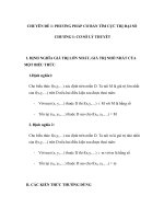
the phase plane. These create
“constellations” of bit symbol
locations such as shown in the
3π/8 shifted-8PSK configuration
of figure 1. This particular mod-
ulation format is used in the
emerging EDGE (Enhanced Data
Rates for GSM Evolution) sys-
tems which will offer high-data-
rate transfer over mobile
wireless channels. By packing
3 bits per symbol, it increases
data information rates, but
thereby increases amplitude
swings up to 16+ dB, making
amplifier saturation more likely.
Each TDMA wireless sub-
scriber’s share of time might
allow a useful data burst of
524.6 µS, during which it is cru-
cial for the power amplifier to
remain below its saturation
region. Driving the output stage
into non-linear amplification
causes the outermost phase
states to compress, thereby
increasing bit errors and lower-
ing system reliability.
Another competitive wireless
modulation technology is called
code division multiple access
(CDMA), such as used in IS-95
wireless systems. CDMA encodes
multiple data streams onto a sin-
gle carrier using a pseudo-
random code, with a resulting
transmitted power spectrum that
exhibits almost white-noise-like
characteristics.
But, just like white noise, the
average power of the transmitted
signal is only one of the impor-
tant parameters. Because of the
statistical way that multiple car-
rier signal voltages can add ran-
domly, instantaneous peak
voltages can approach ratios of
10 to 30 times the rms voltage,
depending on formats and filter-
ing. This ratio, calculated with
voltage parameters, is commonly
called crest factor, and is func-
tionally similar to a peak-to-aver-
age power ratio that is measured
by Agilent peak and average
power meters.
1
System designers handle this
crest-factor effect by “backing
off” the power amplifiers from
their maximum peak ratings to
assure that signal peak power
operation is always within their
linear range.
1. Accepted definition of crest factor (pulsed carrier): The ratio of the pulse peak (voltage) amplitude to the root-mean-square (voltage) amplitude.
Figure 1. This 3π/8 shifted 8PSK digital
modulation format is emerging for wideband
data transmission on wireless channels, such
as the EDGE technology.
6
Two-tone and full-channel formats
Two-tone (or three-tone) test sig-
nals are often used for charac-
terizing amplifiers for linearity
of their amplification. Amplify-
ing two pure input signals of
f
1
and f
2
results in intermodula-
tion signals at the output, of the
form 2f
1
– f
2
, 2f
2
– f
1
,
f
1
× f
2
, and many more.
Measuring power of such tones
needs analysis because the two
carrier’s phases add or cancel in
random. In a two-tone example,
of V
1
and V
2
, each with equal
power P, the constructive addi-
tion of tones results in a peak
carrier of 2V that is a peak
power of 4P. An average-
responding sensor would indi-
cate 2P but a peak-responding
sensor would indicate 4P.
Noise loading tests of microwave
amplifiers involve full-channel
signals, simulated with a white
noise input, except for a single
notched-out (slot-filter) carrier.
If there is non-linear amplifica-
tion, the amount of intermodula-
tion power in the notch at the
output, measures the perfor-
mance of the amplifier.
There are also many examples of
simple CW signal testing. Metro-
logy laboratories would be a typ-
ical application, such as power
sensor calibrators that are dri-
ven by CW test signals. Many
component tests use simple
unmodulated signals for test pro-
cedures.
These above examples are
intended to illustrate that
detailed knowledge of your
unknown signal and its spec-
trum and modulation content is
crucial to your selection of the
best power sensor. In some
cases, CW and averaging sensors
serve commendably. But others
require precise characterization
of the peak power performance
to yield peak-to-average power
ratios or time-gated parameters,
and assure conformity to speci-
fied industry standards.
7
Step 2.
Understanding
measurement uncertain-
ties and traceability to
national standards
The ultimate uncertainty of an
RF or microwave power mea-
surement is a set of national
power standards maintained by
the U.S. National Institute of
Standards and Technology
(NIST) in Boulder, Colorado,
USA. Many other countries also
maintain national power refer-
ences, and regularly perform
comparisons with other stan-
dards in sophisticated measure-
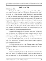
ment assurance processes. These
highly-sophisticated power stan-
dards are called microcalori-
meters (figure 2) and are the
basic reference for measurement
services in coax and waveguide,
with transfer techniques capable
of achieving uncertainties of sev-
eral tenths of a percent.
Figure 2. Schematic cross-section of the
NIST coaxial microcalorimeter at Boulder,
Colorado, U.S.A.
NIST and other country stan-
dards agencies offer fee-based
measurement services for trans-
ferring such standards to cus-
tomer primary labs. They
include comprehensive docu-
mentation of the procedures
with fee schedules and applica-
tion notes which provide
detailed technical descriptions
of the theory and practice of
their measurement processes.
Agilent power instrumentation
and sensor calibrations are
traceable to those NIST stan-
dards, and to certain other
national standards. Agilent per-
forms its sensor production tests
using automatic network analyz-
ers for improved accuracy, by
taking into account the complex
reflection coefficients of each
individual sensor. The sensors
are furnished with calibration
charts that include reflection
coefficient as well as calibration
factor data. With this individual-
ized test data, the user can
reduce measurement uncertain-
ties introduced by that sensor-to-
source mismatch.
8
In recent years, the world’s
metrology and quality communi-
ty has begun to accept and
implement a new process for cal-
culating and reporting the uncer-
tainties of measurement. The
process is based on a standard
promulgated by the International
Standards Organization, Geneva,
Switzerland, “ISO Guide to the
Expression of Uncertainty in
Measurement.”
The NCSL International (previ-
ously National Conference of
Standards Laboratories),
Boulder, Colorado, cooperating
with the American National
Standards Institute, adopted the
ISO document as a U.S. National
Standard, and introduced it in
the USA as an industry docu-
ment, ANSI/NCSL Z540-2-1996,
“U.S. Guide to the Expression of
Uncertainty in Measurement.”
[see reference literature]
Both of the uncertainty stan-
dards operate within a larger
metrology context, specified by
ISO Guide 25, “General
Requirements for the
Competence of Testing and
Calibration Laboratories.” This
document was adapted to a U.S.
version with the identical title,
ANSI/NCSL Z540-1-1994.
Recently, ISO announced the
replacement of ISO Guide 25
with ISO/IEC 17025.
In the U.S., the ANSI/NCSL
industry committee determined
that world metrology would be
best served with a single stan-
dard for general laboratory
requirements, and thus has
begun the process of adopting
the ISO/IEC 17025 document as
a U.S. National Standard in
cooperation with the American
Society of Testing Materials
(ASTM) and the American
Society for Quality (ASQ).
However, the ANSI/NCSL Z540-1-
1994 Standard will be main-
tained at this time to meet the
needs of some elements of U.S.
industry which are not covered
in ISO/IEC 17025. In the future
the continued existence of Z540-
1-1994 may depend on the
extent to which the ISO/IEC
17025 is strengthened through
revision.
The new processes provide more
rigor and standardization to the
combining of all the uncertain-
ties of power parameters from
the mismatch at measurement
and calibration time to the trace-
ability of the 50 MHz reference
source. An extended explanation
of the uncertainty calculation
process is detailed in Chapter 7
of Agilent Application Note
64-1C “Fundamentals of RF and
Microwave Power Measurements,”
literature number 5965-6630E.
In that example, twelve different
uncertainty elements are
combined.
Generally, the dominant mea-
surement uncertainty is the mis-
match between the source under
test and the sensor. Since the
reflection coefficient of the test
source is usually beyond the con-
trol of the user, it is desirable to
choose power sensors with the
lowest specified reflection coeffi-
cient. Agilent sensors are conser-
vatively specified, and the actual
reflection coefficient data for
each sensor is furnished with
the sensor, allowing smaller
uncertainties when the test engi-
neer performs some simple
analysis routines.
9
STEP 3.
Understanding Agilent
sensor technologies and
power meter features
In general, power sensors are
designed to match user signal
formats and modulation types.
Similarly, power meters are
designed to match the user’s
measurement data requirements.
Sensor technology has developed
over the years to better meet the
advancing needs of users. The
thrust has been to increase sen-
sitivity and dynamic range,
while improving the speed, accu-
racy and reliability demanded by
the fast-paced industry.
Power sensors are of two general
types:
1. heat-based
2. diode-detector based
Heat-based sensors such as ther-
mistors and thermocouples
depend on the process of absorb-
ing all (except for tiny inefficien-
cies and reflections) of the RF
and microwave signal energy,
and sensing the resulting heat
rise. Since the heat effect inte-
grates all the signal power, such
sensors are totally independent
of the waveforms and spectrum
content of the signal. Thus, they
respond to the true average
power of the signal, whether
pulsed, CW, AM/FM, or other
complex modulation, and includ-
ing spiked power effects such as
crest factor.
Diode-based sensors depend on
the rectifying characteristics of
their non-linear microwave
detection curve. Their ability to
detect and measure power down
to -70 dBm recommends them
for ultra-low signal detection
applications such as at the front
end of RF or microwave systems.
They are also ideal for wide-
dynamic-range measurements.
And they provide much faster
response times, making them
important for pulsed and high-
data-rate applications.
While basic diode sensors oper-
ate in their “square-law” range
from –70 to –20 dBm, Agilent has
extended the diode technology
into three other areas, extended-
range CW sensors, two-path-
diode-stack sensors for higher
power, and peak and average
sensors, which provide powerful
pulse-power characterization. All
will be described below.
Figure 3. Cross section of Agilent thermocouple
chip. Power dissipated in the tantalum-nitride
resistor heats the hot junction.
Thermocouple technology
Agilent thermocouple sensors
use a heat-based design with
–30 dBm sensitivity and the
high-stability offered by a
chopped-signal amplification
path for the tiny DC signal
generated by the thermal
element. Agilent’s silicon-web
technology (circa 1974), which
absorbs the RF/microwave heat
and drives the silicon/metal
thermocouple element, provided
a major advance in improved
impedance match. See figure 3.
This resulted in lower mismatch
uncertainties and better mea-
surement confidence. The chip
also features a rugged termina-
tion design that withstands
reasonable signal overloads.
Typical modern thermocouple
sensors achieve wide frequency
coverage with coaxial inputs, but
some are configured in wave-
guide up to 50 GHz. With their
dynamic power range of –30
to +20 dBm, they measure
convenient ranges of industry-
common system power.
Silicon
Oxide
SiO
2
Tantalum
Nitride
Ta
2
N
Hot
junction
Web
Diffused
region
Cold
junction
SiO
2
Frame
SiO
2
Gold
Au
Gold
Au
10
Thermocouple sensors depend
on a precise 50 MHz reference
power calibrator, which is resi-
dent in each power meter. Used
in conjunction with an associat-
ed calibration factor, the meter/
sensor combination then accu-
rately transfers traceable power
references to all frequencies of
the sensor bandwidth.
Agilent has also extended the
+20 dBm upper power range of
several families of coaxial ther-
mocouple sensors by including
internal attenuators for 3-watt
and 25-watt maximum inputs up
to 18 GHz. Conveniently, the
attenuator performance is
included in the calibration factor
data for better total accuracy.
The Agilent 8480A/B/H family of
sensors typify this powerful
thermocouple technology.
Thermocouple sensors are rec-
ommended for all systems with
CW, pulsed or complex modula-
tions, because when the signal
format lies within their dynamic
range, you can be assured that
the sensor is responding to total
aggregate (average) power.
For some tests, however, such as
a “mute” test on wireless power
amplifiers (–55 dBm), their lim-
ited sensitivity requires a second
sensor to be used, increasing
test times in some applications.
In addition, measurements at the
low-end of the specified range of
thermocouple sensors (typically
–25 to –30 dBm) sometimes
require time-averaging to pro-
duce an accurate, stable reading.
Diode technology
Diodes convert RF/microwave to
DC (or video in pulsed applica-
tions) by means of their rectifi-
cation properties, which arise
from their non-linear current-
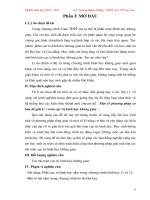
voltage characteristic. Figure 4
shows a typical diode detection
response curve starting near
their noise level of –70 dBm and
extending up to +20 dBm.
Figure 4. The diode detection characteristic
is square law from the noise level up to
–20 dBm, followed by a transition region and
then a linear range to +20 dBm. The lower
graph shows deviation from “square-law.”
In the lower “square-law”' region
the diode's detected output volt-
age is linearly proportional to
the input power (V
out
propor-
tional to V
in
2
) and so responds
linearly to power. Above
–20 dBm, the diode's transfer
characteristic transitions toward
a linear detection function (V
out
proportional to V
in
) , and the
square-law relationship is no
longer valid.
Traditionally, diode power
sensors have been specified to
measure power over the –70 to
–20 dBm range, making them
the preferred sensor type for
applications that require high
sensitivity measurements. In
applications that require fast
measurement speed, diode
sensors are chosen over thermo-
couple types because of their
quicker response to changes of
input power.
Diode sensors (Agilent’s 8480D-
family) average the effects of
complex and multiple signals
within their square-law range
from –70 to –20 dBm, with the
proviso that no peak energy can
exceed the –20 dBm level. This
limits their use considerably for
pulsed power measurement. The
diode elements have also been
designed into waveguide sensors,
with coverage from 26.5 to
110 GHz (8486-series).
–
70 –60 –50 –40 –30 –20 –10 0 +10 +20
100nv
10µv
1mv
100mv
10v
Detected Output –v
1µv
100µv
10mv
1v
Input Power -dBm
–60 –50 –40 –30 –20 –10 0 +10 +20
–14
–10
–6
–2
+2
Deviation from Square Law –dB
–12
–8
–4
0
Input Power -dBm
11
Extended dynamic-range
diode sensors
Agilent diode sensor technology
now permits measuring continu-
ous wave (CW) power over an
extended dynamic range from
–70 to +20 dBm, up to a frequen-
cy range of 26.5 GHz. Their
90-dB range makes them ideal
for wide-dynamic range applica-
tions such as high-attenuation
component measurements. When
these sensors are used with the
EPM series power meters, they
offer a fast measurement speed
mode – up to 200 readings/
second with the single channel
E4418B meter.
These E4412/13A sensors
employ a combination sensor-
meter architecture, whereby the
calibration factor is measured
and stored in an EEPROM with-
in each individual sensor, and
downloaded into the meter.
Since the correction factors are
derived from a CW source, they
do not provide an accurate aver-
age power reading for modulated
signals, such as CDMA, when the
signal peaks rise above the
diode’s square law region.
Two-path-diode-stack sensors
When power testing from
–70 dBm up to +20 dBm is nec-
essary, as has become increas-
ingly the case, the traditional
approach has been to use a
diode sensor to cover the low
range, and a thermocouple
sensor for the high end. In a
high-volume manufacturing
environment, this dual measure-
ment configuration consumes
too much test time, especially if
optimum accuracy must be
maintained.
The ideal averaging sensor
would combine the accuracy and
linearity of a thermal sensor
with the wide dynamic range of
the extended diode approach.
Agilent’s E-series sensors based
on a patented dual-path, diode-
attenuator-diode topology, have
the advantage of always main-
taining the sensing diodes within
their square law region and
therefore responding correctly to
complex modulation formats.
The E-series E9300 power
sensors are implemented as a
Modified Barrier Integrated
Diode (MBID). The MBID is com-
prised of a two-diode-stack pair
for the low power path, a resis-
tive attenuator and a five-diode-
stack pair for the high power
path, as shown in figure 5. Only
one path is active at a time, and
switching between paths is fast,
automatic and transparent to
the user, effectively producing an
80 dB dynamic range over –60 to
+44 dBm, depending on the
sensor model.
Figure 5. Simplified block diagram of the two-
path-diode-stack topology.
This innovative approach has the
important application advantage
of making the sensor capable of
handling higher power levels
without damage, than simple
diode sensors. This is particular-
ly useful with W-CDMA signals,
which exhibit high peak-to-aver-
age ratios.
These MBID sensors have a max-
imum average power specifica-
tion of +25 dBm and +33 dBm
peak (<10 µS duration). This
means that the full 80 dB
dynamic range can be used to
measure signals that simultane-
ously have both high peak power
and high average power.
The new sensor technology facil-
itates an inherently broadband
average power measurement
technique, limited by none of the
bandwidth or dynamic range
trade-off considerations found in
sampled techniques. These sen-
sors are an ideal fit for users
who need the flexibility to make
wideband average power mea-
surements.
Together with the new E-series
E9300 power sensors, the com-
panion Agilent EPM power
meters (E4418B/19B) are capa-
ble of accurately measuring the
average power of modulated sig-
nals over a wide dynamic range,
regardless of signal bandwidth.
Lsense -
Lsense +
Hsense +
Hsense -
RF in
12
Peak and average power sensors
The Agilent E9320 peak and
average sensors presently cover
the 50 MHz to 6/18 GHz frequen-
cy ranges and -65 to + 20 dBm
power range. They are optimized
for comprehensive measure-
ments on pulsed envelopes and
signals with complex modula-
tion. When teamed with the new
Agilent EPM-P series power
meters (E4416A/17A), the com-
bination can handle test signal
envelopes with up to 5 MHz
video
2
bandwidth.
Of particular utility for produc-
tion testing, the meters’ 20
Msamples/second continuous
sample rate permits fast mea-
surement speed, via the GPIB, of
up to 1,000 corrected readings
per second, ideal for use in auto-
matic test system applications.
Agilent peak and average sen-
sor/meters feature two-mode
operation, normal for most aver-
age and peak measurements
(with or without time gating),
and average only for average
power measurements on low
level or CW-only signals. Both
modes use the same micro-cir-
cuit diode-sensor element.
The signal processing is provided
by two amplification paths, each
optimized to their different data
requirements. The amplification
is distributed, with some in the
sensor unit and more in the
meter. In the average-only
mode, amplification and chop-
ping parameters are much the
same as in previous Agilent
diode sensors, with typical
dynamic power range of –65 to
+20 dBm.
Bandwidth considerations
In the normal mode, the sepa-
rate-path pulse amplifier pro-
vides maximum bandwidths of
300 kHz, 1.5 MHz or 5 MHz,
defined by the sensor model
number. This allows the user to
match the test signal’s modula-
tion bandwidth to the sophisti-
cated instrument data process-
ing. For example, the three maxi-
mum bandwidth choices match
up with these typical wireless
system requirements:
300 kHz TDMA, GSM
1.5 MHz CDMA, IS-95
5 MHz W-CDMA, cdma2000
To further optimize the system’s
dynamic range, the video band-
width can be user-selected inside
the meter amplifier to high,
medium, and low, as detailed in
table 1. Thus, when users need
to measure the power of multiple
signal types, within a single sen-
sor, by considering the dynamic
range of the bandwidth settings
shown, they can determine if
they require only one sensor or
need multiple sensors for their
application(s).
When instrumenting for peak
power measurements, it is cru-
cial to analyze the effect of the
instrumentation video band-
widths on the accuracy of the
resulting data. Agilent E4416/17A
meters have been optimized to
avoid degrading key specifica-
tions like linearity, mismatch,
dynamic range and temperature
stability. For further information
on this matter, see the following
article, “Power Measurements for
the Communi-cations Market.”
3
Measurement accuracy is
enhanced without compromise,
since the sensors store their
three-dimensional calibration
data in an EEPROM, resident in
each sensor. The data is unique
to each sensor and consists of
cal factor vs. frequency vs.
power input vs. temperature.
Upon power-up, or when the
sensor is connected, these cali-
bration factors are downloaded
into the EPM-P series power
meters.
2. Note that the video bandwidth represents the ability of the power sensor and meter to follow the power envelope of the input signal. The power envelope of the input
signal is, in some cases, determined by the signal's modulation bandwidth, and hence video bandwidth is sometimes referred to as modulation bandwidth.
3. Anderson, Alan. “Power Measurements for the Communications Market,” MW/RF Magazine, October 2000.
Table 1. E9320 sensor bandwidth versus peak power dynamic range (normal mode)
Sensor model Modulation bandwidth / Max. dynamic range
6 GHz/18 GHz
High Medium Low Off
E9321A/E9325A 300 kHz / –42 dBm 100 kHz /–43 dBm 30 kHz / –45 dBm –40 dBm to +20 dBm
to +20 dBm to +20 dBm to +20 dBm
E9322A/E9326A 1.5 MHz / –37 dBm 300 kHz /–38 dBm 100 kHz /–39 dBm –36 dBm to +20 dBm
to +20 dBm to +20 dBm to +20 dBm
E9323A/E9327A 5 MHz / –32 dBm 1.5 MHz /–34 dBm 300 kHz /-36 dBm –32 dBm to +20 dBm
to +20 dBm to +20 dBm to +20 dBm
13
Thermistor technology
Agilent maintains a line of coaxi-
al and waveguide thermistor
sensors and one thermistor
power meter. Thermistor sensors
are heat-based, and exploit a bal-
anced-bridge architecture using
the DC substitution method.
Thus, they are ideally suited for
metrology-type applications such
as transferring a reference
power level from the primary
standards of a national laborato-
ry, or for an industry intercom-
parison process called a Round
Robin.
The Agilent 432A power meter
and associated 478/86 sensors
and their role in traceability
processes is fully detailed in
Chapter 3 of AN 64-1C. Custom
versions of the thermistor sen-
sors, which feature selected low
reflection coefficients, are avail-
able for the lower uncertainties
they provide to reference power
transfer applications.
Agilent power meters
Agilent offers power meters in
four basic families. (See table 2.)
1.The E4416/17A series for peak
and average applications. They
have the highest functionality
and most versatile measure-
ment capability. Moreover,
they are backward compatible
with all Agilent thermocouple
and diode power sensors.
2.The E4418/19B series for
averaging power measure-
ments. They offer full
capabilities for average power
applications, thus utilizing all
but the E9320-series peak/
average sensors.
3.The 70100A (MMS) and
E1416A (VXI) system power
meters, which are compatible
with the 8480-series sensors.
4.The 432A/478/486 thermistor
family, which is preferred for
metrology applications such as
reference power transfer.
Table 2. Agilent’s family of power meters
Agilent model Name Remarks
Peak and average
power meters
EPM-P series
E4416A
Single-channel Digital, programmable, peak and average measure-
ments, uses E9320 series sensors. Innovative time-
gated pulse-power measurements. 20 Msamples/sec.
E4417A
Dual-channel Two-channel version of E4416A, plus measures and
computes parameters between the two sensors.
Averaging
power meters
EPM series
E4418B
Single-channel Digital, programmable, uses E-series and 8480 series
sensors, reads EEPROM-stored sensor calibration
factors of E-series sensors.
E4419B
Dual-channel Two-channel version of E4418B, plus measures and
computes parameters between the two sensors.
System
power meters
E1416A
VXI power meter Both have functional performance features of
70100A
MMS power meter previous model 437B. Both use all 8480-series
sensors
Thermistor
power meter
432A Thermistor power meter
DC-substitution, balanced-bridge technology, ideal for
reference power transfers
14
Peak and average meters
(EPM-P series)
The E4416/17A peak and aver-
age power meters (EPM-P series)
are Agilent’s most powerful mea-
surement tools for pulsed and
complex modulation formats. In
combination with the E9320 sen-
sors, they feature a user-friendly
interface and powerful display
controls.
Hardkeys control the most-fre-
quently used functions such as
sensor calibration and triggering,
while softkey menus simplify
configuring the meter for de-
tailed measurement sequences.
A save/recall menu stores up to
10 instrument configurations for
easy switching of test processes.
And, in its GPIB programming
mode, it can output up to 1,000
corrected readings per second.
The powerful DSP (digital signal
processing) mathematical pro-
cessing permits the meter to
measure burst-average and peak
power, to compute peak-to-aver-
age ratios, and display other
time-gated pulse power profiles
on the power meter's large LCD
screen. They can also measure
and display other complex wide-
band modulation formats whose
envelopes contain high frequen-
cy components up to 5 MHz.
For time-gated measurements,
the EPM-P series meters excel in
versatility. The power meters
measure peak and average pow-
ers at user-designated time-gates
and gate widths along a test
waveform. Figure 6 shows anoth-
er typical time-gated power mea-
surement on a GSM signal. Gate
2 provides the burst average
power over the “useful” GSM
time period and Gate 1 indicates
the peak power over the com-
plete timeslot. Thus, a peak-to-
average ratio measurement can
be obtained by subtracting Gate
1 - Gate 2 (in dB).
Figure 6. On this GSM pulse, powerful data
configuration routines during four gate times,
provide the feeds for the display.
This peak-to-average measure-
ment made as shown, was using
two different gate times and
should not be confused with the
peak-to-average ratio measure-
ment in a single gate. A pulse
droop measurement can be
obtained from the subtraction of
the two powers, Gate 3 - Gate 4.
With the 4-line numeric display,
all 3 of these measurements can
be simultaneously display on the
LCD screen, along with the peak
power from Gate 1.
Computation power
By configuring the data obtained
from the four gate periods, the
E4416/17A meters can present
computed data on their large
LCD displays. For example, fig-
ure 8 shows the data paths for
the four independent gate peri-
ods. Each gate can accumulate
three different parameters; aver-
age, peak, or peak-to-average
ratio.
Each gate can then manipulate
the selected parameter into two
computed parameters (F-feeds)
per measurement channel (maxi-
mum), such as F1 minus F2 or
F1/F2, to be displayed in one of
the four window partitions. This
computational power is particu-
larly valuable in TDMA scenarios
such as GSM, GPRS, EDGE, and
NADC where various simultane-
ous combinations of computed
parameters are required.
This computational power is fur-
ther enhanced in the E4417A
dual-channel power meter, which
can add data feeds from its sec-
ond sensor into the user-config-
ured display modes.
A large LCD display partitions
up to 4-line formats to help inter-
pret and compare measurement
results, or presents large charac-
ter readouts to permit viewing
from a distance. For example, the
4 lines could be configured to
display average power in dBm
and mW, peak power and peak-
to-average ratio. The user can
also set up a trace display as
shown in figure 7.
Gate 3
Gate 4
Gate 2
Gate 1
Figure 7. E4417A power meter configured to show a trace display (upper
window) and a dual numeric display (lower window).
15
Averaging power meters
(EPM series)
Average power meters respond
to all signals, whether CW, com-
plex modulation or pulsed. The
main application criteria is
whether the user needs to char-
acterize the modulation or pro-
file the envelope of those pulse
parameters or simply requires a
measurement of average power.
In some cases of traditional
pulsed signals, where the duty
cycle is known and fixed, system
peak powers may be computed
from a knowledge of the duty-
cycle value and an average
power measurement.
The E4418/19B power meters
and E-series sensor combination
provides measurement speeds of
up to 200 readings per second
over the GPIB bus. The E-series
sensors cover a 90-dB power
range from –70 to +44 dBm, with
frequency coverage to 26.5 GHz,
sensor dependent. For CW,
multi-tone and modulation appli-
cations, the E-series sensors can
make measurements using only a
single sensor rather than several
of the 8480 series as before.
Agilent EPM series meters oper-
ate with the entire line of 8480
series thermocouple and diode
sensors, to protect your equip-
ment investment. Programming
code, written for the previous
436A, 437B and 438A power
meters, is also directly usable
with the E4418B and E4419B
power meters.
System power meters
Agilent offers two models of
power meters, intended for sys-
tem applications, the industry-
standard VXI configuration, and
the MMS system configurations.
Both have the functional perfor-
mance and operating features of
the previous 437B power meter,
except they have no front panel.
Gates 1 to 4
Measurement feeds
(single or combined)
Display
12 measurement highway
Gate 1
Upper window
Upper measurement
Upper window
Lower measurement
Lower window
Upper measurement
Lower window
Lower measurement
Gate 2
Gate 3
Gate 4
Feed 1
Feed 2
Single
Feed 1 – Feed 2
Feed 1 / Feed 2
Combined
Feed 1
Feed 2
Single
Feed 1 – Feed 2
Feed 1 / Feed 2
Combined
Feed 1
Feed 2
Single
Feed 1 – Feed 2
Feed 1 / Feed 2
Combined
Feed 1
Feed 2
Single
Feed 1 – Feed 2
Feed 1 / Feed 2
Combined
Peak
Average
Pk-to-avg
Peak
Average
Pk-to-avg
Peak
Average
Pk-to-avg
Peak
Average
Pk-to-avg
Figure 8. User-configured data manipulations are one big feature of the EPM-P series power meters.
16
STEP 4.
Making the performance
comparison and selecting
the best product for your
application
By far, most power measure-
ments are made with averaging
power meters. Based on the pre-
vious comparison of sensor tech-
nology, and the selection guide
for sensors (see below), the user
can easily determine which sen-
sor model meets the power and
frequency range performance
required. The compatibility
table 3 shows which meters
operate with which
sensors.
For averaging applications, the
two EPM power meters are
prime alternatives, since not
only are they designed for the
E-series CW and E9300 sensors,
but they are also backwards-
compatible with the entire line
of 8480 thermocouple and diode
sensors (but not thermistors).
Consider-ing the large installed
base of Agilent sensors in most
organizations, this makes the
EPM meters far more versatile
and cost effective. Further, many
calibration laboratories are func-
tional with test systems which
are designed specifically to cali-
brate Agilent’s long line of power
sensors.
In spite of the popularity of aver-
aging meters, the rapid growth
of the wireless communications
industry has driven measure-
ment requirements into power
characterizations of peak power,
peak burst, peak-to-average
ratio, burst average power, and
other important parameters.
Agilent’s peak and average
E4416/17A EPM-P meters are
innovative solutions to the strin-
gent needs of the industry. If you
need peak power characteriza-
tion in your lab or production
line, the Agilent EPM-P meters
are your choice. They are func-
tionally the most versatile and
computational of our power
meter line.
In the benchtop or production
line environment, selecting
between single- and dual-channel
capability gives the next sort.
Agilent’s meters have means of
sensing the specified power
range of the individual sensor
attached, and thus assure the
correct power readout. This fea-
ture also disables the readout if
the user applies too much power
and drives the meter outside the
specified range, such as the
standard 8480 series diode
sensors which are limited to a
top level of –20 dBm.
In terms of GPIB programming
code, as well as complying to the
Standard Commands for
Programmable Instruments
(SCPI), the E4418B power meter
has been designed to be code-
compatible with the previous
436A and 437B. The E4419B
dual channel power meter is
code-compatible with the
previous 438A. This provides
a substantial saving in new pro-
gram- ming costs. Yet, the EPM
series power meters offer flexi-
bility, accuracy, and convenience
for manual applications in the
research lab.
For automated system use,
the fast measurement speed,
(EPM–200 readings per second,
EPM-P—1,000 readings per sec-
ond) make them ideal for pro-
grammed applications. Their
digital-signal-processing (DSP)
circuit architecture not only pro-
vides for powerful computation
and averaging routines, but also
results in the elimination of the
standard range switch-time
delays, thus speeding up the
overall measurement speed.
Thermistor-based sensors and
meter for metrology applications
Finally, Agilent offers a line of
coaxial and waveguide thermis-
tor sensors and a full DC-substi-
tution power meter, the 432A,
which serves metrology applica-
tions for the transfer of power
standards.
17
Selection guides
Power measuring equipment
for all applications
Power measuring equipment is a
key part of Agilent’s instrumen-
tation line of RF and microwave
measurement tools. Through the
decades, the power-meter line
has advanced with additions of
the newest sensor technologies
and the power of the micro-
processor for more capable and
flexible power meter products.
From the original drift-prone
thermistor sensors of the 1950’s,
to low-SWR thermocouple sen-
sors, Agilent has exploited the
latest technologies to take the
inaccuracies out of your power
measurements. The latest sensor
technologies that use planar-
doped-barrier diodes in various
configurations now offer the best
in sensitivity and low drift for
both average-power and peak-
power measurements. And
Agilent’s newest power meters
and E-series sensors give you
new speed and accuracy for
measurements over a dynamic
range of –70 to +44 dBm, sensor
dependent.
Table 3 presents a compatibility
overview of the entire Agilent
power measurement family,
including meters and sensors.
Table 3. Agilent power meter/sensor compatibility chart
Agilent power meters
EPM-P series EPM series System power Thermistor
peak, average and averaging meters power meter
time gating E4418B single Ch 70100A MMS 432A
Agilent
E4416A single Ch E4419B dual Ch E1416A VXI
power sensors
E4417A dual Ch
Thermocouple
8480A/B/
H-family •••
R/Q8486A W/G
(11 models)
Diode
8480D-family
8486A/D-W/
•••
G-family
(7 models)
Diode sensors
with extended
range
••
E4412A/13A
(2 models)
Two-path-
diode-stack
••
E9300 family
(7 models)
Peak and
average
sensors
•
E9320 family
(6 models)
Thermistor
sensors
478 coaxial
•
486 waveguide
(6 models)
18
Agilent’s family of versatile sensors
Table 4. Agilent's family of power sensors
Thermocouple sensors
Diode sensors
Extended range diode sensors
Thermocouple sensors
25 W, 0 to +44 dBm
3 W, -10 to +35 dBm
100 mW, -30 to +20 dBm
8482B
8482H
8481B
8481H
8481A
8483A .75 Ω
8485A
Opt 33
W/G
8487A
Q8486A
Frequency
100 kHz
10 MHz
50
100
500 MHz
1 GHz
2
4.2
18.0
26.5
33
40
50
75
110 GHz
8482A
W/G
Sensor family
8480 series
Technology
Thermocouple
Max. dynamic
range
50 dB
Frequency range
1
100 kHz to 50 GHz
Power range
1
Signal type
Max. measurement
speed (rdgs/sec)
-30 to +44 dBm
All signal types,
unlimited bandwidth
40 (x2 mode)
R8486A
Diode sensors
10 µW, -70 to -20 dBm
Frequency
100 kHz
10 MHz
50
100
500 MHz
1 GHz
2
4.2
18.0
26.5
33
40
50
75
110 GHz
8481D
8485D
Opt 33
8487D
R8486D
Q8486D
W8486A
-30 to +20dBm
W/G
W/G
W/G
-30 to
+20dBm
V8486A
W/G
Sensor family
8480 series
Technology
Diode
Max. dynamic
range
50 dB
Frequency range
1
10 MHz to 110 GHz
Power range
1
Signal type
Max. measurement
speed (rdgs/sec)
-70 to -20 dBm
All signal types,
unlimited bandwidth
40 (x2 mode)
100 mW, -70 to +20 dBm
Frequency
100 kHz
10 MHz
50
100
500 MHz
1 GHz
2
4.2
18.0
26.5
33
40
50
75
110 GHz
E4412A
E4413A
Sensor family
E-series: CW
E4412A
E4413A
Technology
Single diode pair
Max. dynamic
range
90 dB
Frequency range
1
10 MHz to 26.5 GHz
Power range
1
Signal type
Max. measurement
speed (rdgs/sec)
-70 to +20 dBm CW only 200 (fast mode)
100 mW, -70 to +20 dBm
Extended dynamic
range diode sensors
1. Sensor dependent
19
Two-path diode stack sensors
Peak and average sensors
100 mW, -60 to +20 dBm
Frequency
9 kHz
100 kHz
10
50 MHz
100 MHz
500
1 GHz
6
18.0
26.5
33
40
50 GHz
E9300A
E9301A
Sensor family
E-series:
average power
sensors E9300
Technology
Diode-attenuator-
diode
Max. dynamic
range
80 dB
Frequency range
1
9 kHz to 18 GHz
Power range
1
Signal type
Max. measurement
speed (rdgs/sec)
-60 to +44 dBm All signal types
unlimited bandwidth
200 (fast mode)
100 mW, -60 to +20 dBm
Two path diode
stack sensors
25 W, -30 to +44 dBm
25 W, -30 to +44 dBm
1 W, -50 to +30 dBm
1 W, -50 to +30 dBm
100 mW, -60 to +20 dBm
1 MHz
E9304A
E9300H
E9301H
E9300B
E9301B
100 mW,
Avg. only: –65/60/60 to +20 dBm
Normal –50/45/40 to +20 dBm
100 mW,
Avg. only: –65/60/60 to +20 dBm
Normal –50/45/40 to +20 dBm
Frequency
100 kHz
10
50 MHz
100 MHz
500
1 GHz
6
18.0
26.5
33
40
50 GHz
E9321A 300 kHz
E9322A 1.5 MHz
Sensor family
E9320-series
2
peak and average
E9321/22/23A
E9325/26/27A
Technology
Single diode
pair, two-path
Max. dynamic
range
85 dB
Frequency range
1
50 MHz to 18 GHz
Power range
1
Signal type
Max. measurement
speed (rdgs/sec)
–65 to +20 dBm
CW, avg, peak Up to 1000
1 MHz
E9323A 5 MHz
E9325A 300 kHz
E9326A 1.5 MHz
E9327A 5 MHz
1. Sensor dependent
2. Peak and average sensors must be used with an E9288A, B, or C sensor cable, and only operate with the E4416A/17A power meters
By internet, phone, or fax, get assistance
with all your test & measurement needs
Online assistance:
www.agilent.com/find/assist
Phone or Fax
United States:
(tel) 1 800 452 4844
Canada:
(tel) 1 877 894 4414
(fax) (905) 282-6495
Europe:
(tel) (31 20) 547 2323
(fax) (31 20) 547 2390
Japan:
(tel) (81) 426 56 7832
(fax) (81) 426 56 7840
Latin America:
(tel) (305) 269 7500
(fax) (305) 269 7599
Australia:
(tel) 1 800 629 485
(fax) (61 3) 9210 5947
New Zealand:
(tel) 0 800 738 378
(fax) 64 4 495 8950
Asia Pacific:
(tel) (852) 3197 7777
(fax) (852) 2506 9284
Product specifications and descriptions
in this document subject to change
without notice.
Copyright © 2000
Agilent Technologies
Printed in USA, December 28, 2000
5965-8167E
More information on Agilent
Technologies’ power meters and
sensors is available at:
www.agilent.com/find/powermeters
References
1. International Organization for Standardization, Geneva
Switzerland, ISBN 92-67-10188-9, 1995.
2. National Conference of Standards Laboratories, Boulder, CO,
ANSI/NCSL Z540-2-1996.
3. Anderson, Alan, Power Measurements for the Communications
Market, MW/RF Magazine, October, 2000.
For more information:
Choosing the Right Power Meter and Sensor, Product Note,
literature number 5968-7150E.
Fundamentals of RF and Microwave Power Measurements,
Application Note, literature number 5965-6630E.
Related Literature
EPM-P Power Meters and the E9320 Series Power Sensors,
Technical Specification, literature number 5980-1469E.
EPM and EPM-P Series Power Meters and E-Series Power Sensors,
Configuration Guide, literature number 5965-6381E.
EMP-P Series Single and Dual-Channel Power Meter-E9320 Family
of Peak and Average Power Sensors, Product Overview,
literature number 5980-1471E.