Menaa MS 05 1600 011 (pre stress cable construction plan) 2013 0918
Bạn đang xem bản rút gọn của tài liệu. Xem và tải ngay bản đầy đủ của tài liệu tại đây (15.14 MB, 156 trang )
AL MENAA SPORT COMPLEX – MAIN STADIUM
OWNER:
IRAQ MINISTRY OF YOUTH AND SPORTS
Ministry Headquarters
Baghdad-Iraq
CONSULTANT:
THREESISTY ARCHITECTURE, INC.
300 West 22
nd
Street
Kansas City, MO 64108-USA
STRUCTURAL ENGINEER:
THORNTON TOMASETTI
912Broadway Boulevard
Suite 100
Kansas City, MO 64105-USA
MAIN CONTRACTOR:
ANWAR SOURA GENERAL CONT. CO. LTD.
Pre-stress Cable Construction Plan of Iraq Al-Menaa Stadium
Date: September 9, 2013; Version: 0
Prepared by:
REJECTED
EXCEPTIONS NOTED
NO EXCEPTIONS
THORNTON TOMASETTI, INC. (TT)
THIS SUBMITTAL CONCERNS ITEMS NOT DESIGNED BY TT.
REVIEW IS LIMITED TO ASSESSING, WHERE REQUIRED BY
THE CONTRACT DOCUMENTS, THE STRUCTURAL EFFECT OF
THE LOADS IMPOSED BY THE REVIEWED ITEM ON THE
STRUCTURAL SYSTEM DESIGNED BY TT, AND/OR
CONFIRMING, BASED SOLELY ON THE REPRESENTATIONS
BY THE CONTRACTOR, ITS SUBCONTRACTORS OR
VENDORS OR THEIR ENGINEER ("CONTRACTOR"), THAT THE
ITEM REVIEWED CONFORMS WITH ANY APPLICABLE
PERFORMANCE CRITERIA ESTABLISHED BY TT IN THE
CONTRACT DOCUMENTS AND/OR ANY APPLICABLE
PARAMETERS ESTABLISHED BY TT IN THE CONTRACT
DOCUMENTS. SUCH REVIEW DOES NOT CONSTITUTE AN
INDEPENDENT CONFIRMATION BY TT THAT SUCH
REPRESENTATIONS BY THE CONTRACTOR ARE ACCURATE.
THE CONTRACTOR REMAINS SOLELY RESPONSIBLE FOR
COMPLIANCE WITH THE REQUIREMENTS OF THE CONTRACT
DOCUMENTS INCLUDING ANY PERFORMANCE CRITERIA
AND/OR PARAMETERS.
By
Date:
APL
17 SEPT. 2013
Menaa MS-05 1600-011
APL/TT
18 Sept 2013
Pre-stress Cable Construction Plan of
Iraq Al-Menaa Stadium
Contents
Chapter 1 Compilation Reference 1
Chapter 2 Erection Summary and Analysis of Construction Key Points 2
2.1 The Erection Summary 2
2.2 Construction control key points and solutions 5
Chapter 3 Construction Process 7
3.1 The construction idea 7
3.2 The construction process 7
Chapter 4 Cable installation & implementation plan 8
4.1 Previous preparation 8
4.1.1 Installation of the mast 8
4.1.2 Set up ring cable packway at stand 12
4.1.3 Erection of high-altitude operation platform 13
4.1.4 Erection of lower cable operation platform 13
4.1.5 Counterforce holes of upper cable ear plate and lower cable ear
plate 14
4.2 Laying down and assembling the cable 16
4.2.1 Install the stay cable 16
4.2.2 Release the ring cable in the ground 18
4.2.3 Lay down the ring cable to the packway 21
4.2.4 Hoist cable clamps 25
4.2.5 Connect the lower cable with cable clamp 28
4.2.6 Lay down the upper ring cable 29
4.2.7 Link the ring cable connector 30
4.2.8 Lay down radial cable on the stand 31
4.2.9 Lay down lower cable 35
4.2.10 Connect the upper’s tooling cable 36
4.3 Installation of the upper cable 38
4.4 Installation of the lower cable 41
4.4.1 Conversion tooling to lower cable and synchronous traction 41
4.4.2 Tense the lower cable in place synchronously 42
4.5 Construction equipments and instruments list 43
Chapter 5 Simulation Calculation of Construction 45
5.1 Installation of Mast 45
5.2 Installation of Stay cable 53
5.3 Simultaneously Ascending of Upper Suspension Cable 54
5.4 Simultaneously Ascending of Lower suspension Cable 84
5.5 Conclusion 104
Chapter 6 Monitoring of Construction Process 105
6.1 Principle of Construction Monitoring 105
6.2 Monitoring of Cable Force 105
6.2.1 Measurement Method of Cable Force 105
6.2.2 Record Form of Cable Force Measurement 105
6.3 Monitoring of Structural Deformation 109
6.3.1 Measurement Method 109
6.3.2 Record Form of Measurement 109
Chapter 7 Control of Construction Process and Data Submission 111
7.1 Control Indexes of Construction 111
7.2 Construction Data Content 112
Chapter 8 Decomposition of Project Content 113
Chapter 9 Construction Case of Similar Projects 114
9.1 Panjin Stadium 114
9.1.1 Project Overview 114
9.1.2 Construction Way 116
9.1.3 Pictures of Construction Process 116
9.2 Foshan international furniture expo city 134
9.2.1 Project Overview 134
9.1.2 Construction Scheme 135
9.2.3 Pictures of Construction Process 135
9.3 Xuzhou Olympic Sports Center Stadium 144
9.3.1 Project Overview 144
9.3.2 Construction Way 146
9.3.3 Pictures of Construction Process 146
9.4 Comparison of Labor, construction time and equipment 151
1
Chapter 1 Compilation Reference
1 Calculation model provided by design unit
2 This project’s construction drawings of construction structure and steel
structure
3 Construction progress of the related units and overall construction & erection
progress plan
4 Designed construction drawings and product specifications of related
manufacturers
2
Chapter 2 Erection Summary and Analysis of Construction Key
Points
2.1 The Erection Summary
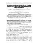
The Iraq Al-Menaa Stadium is a long span cable-membrane structure. The plane
shape is oval, the maximum size of the long axis is about 276m and the maximum
size of the short axis is about 232m, and the maximum height of the mast is about
45m. The whole structure is constituted by the outer steel frame, the main cable
system of the roof and the membrane roof. The outer steel frame is constituted by
shuttle-shaped column, steel truss and toroidal pressure ring. The main cable system
of the roof includes stay cable connected to the mast, upper cable and lower cable
respectively 48 root, 48 root valley cable at the membrane surface, 16 root cross cable
of the mast and a ring cable (8 root); the membrane surface is arranged between the
steel truss and truss, and it across 48 root valley cable to form the undulating surface
modeling. The stadium structure’s layout drawing, three-dimensional diagram, single
cross layout drawing and the related nodes drawing are shown below.
3
Layout drawing
The Iraq Al-Menaa stadium three-dimensional diagram
4
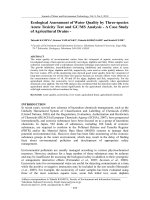
The overall elevation drawing
Single cross section drawing
Upper cable: 900KN
Lower cable: 700KN
Stay cable: 1150KN
Ring cable: 1850KN
5
The mast end node Ring cable-ridge cable node
The cable quantity and specification of the Iraq Al-Menaa Stadium
Cable
position
Cable
specifications
Cable
number
Length of the cable
Upper cable
Φ80
48 root
34m
Lower cable
Φ55
48 root
28m
Stay cable
Φ115
48 root
42m
Ring cable
Φ65
32 root
8 root of a ring cable,4 segment
of a root,130m/segment
Cross cable
Φ55
16 root
24m
2.2 Construction control key points and solutions
Key Point 1: The fix of the mast, the installation of the stay cable
Solution: Through the two wind ropes to reinforce the mast, through the crawler
crane to install the stay cable’s fixed end and the through the tool to install the
adjustable end.
Key Point 2: How to guarantee the stability of the mast in the process of
ascension
This stiffness of the engineering’s peripheral structure is relatively weaker than
other similar structures, the mast will form large deformation in the whole process of
ascension so must ensure the stability of the mast (especially the lateral stability)
Solution: By reasonable arrangement of wind rope to ensure lateral stability of the
mast, observing the deformation of the mast at any time in the process of ascension
and immediately taking measures to rectify if the deformation exceeds a certain value.
6
Corrective measures: by adjusting the length of the wind rope to rectify or tensile
local axis of cable to rectify. Concrete plans need to bring bias into the calculation
model to analysis to determine.
Key Point 3: The error analysis and influences
The influence of construction error on structure includes steel structure
processing error, cable blanking error and construction of sync impact on
construction.
Solution: For steel structure processing error, measuring the coordinates of
control points after finishing assembling steel structure to determine the deviation of
steel structure construction; for cable blanking error, by pre-tense the cable in the
manufacturer and accurate measurement to determine the deviation of cable blanking
error; taking the construction error and all kinds of possible sync into the calculation
model to analysis.
We considered the various possible operating conditions when making
construction plan and analyzed each operating condition to find out the condition
which is not easy to control and the more possibility of occurring. Select the
equipment type according to the found conditions, by predicting in advance and
strictly controlling in the process of management to avoid unfavorable conditions for
other adverse conditions.
In addition, it needs detailed technical clarification and training and strict
monitoring in the process to solve the technical difficulties that due to the
construction process and strictly control of site operation.
7
Chapter 3 Construction Process
3.1 The construction idea
The idea of pre-stressed cable total construction is: erect the mast and ring beam
firstly, then install the stay cable and at the same time hoist the upper cable and install
it in place, lastly, install the lower cable.
3.2 The construction process
Install the mast (fix by wind rope)
Install the ring beam
Loosen the wind rope
Install the back cable
Set up ring cable packway in the stands
Lay down the lower ring cable
Install the cable clip and put the
lower ring cable into the slot
Lay down the upper ring cable
and put them into the slot
Lay down the lower cable and connect
it to the ring beam by the strands
Lay down the upper cable and connect
it to the ear plate by tooling
Lay down the lower cable and connect
it to the ring beam by the strands
48 masts improve the upper
synchronously and install it
Lay down the lower cable
8
Chapter 4 Cable installation & implementation plan
The installation and tension of cable is the key process in the process of
structural construction that serves as a link between the construction of steel structure
and cable membrane and it has high technical difficulty. It needs to develop detailed
construction process from previous preparation to construction process and process
control in order to ensure the construction of cable smoothly.
4.1 Previous preparation
The cable construction previous preparation work includes: the installation of the
surrounding steel structure, the precise measurement of the steel structure
construction error, the precise measurement of the cable blanking error , the ring cable
construction packway erection, the operating platform erection of the upper cable and
lower cable.
4.1.1 Installation of the mast
Using crawler crane to lift the mast and each mast use 2 wind ropes for
temporary fixation. Install the ring beam between the masts after fishing every two
mast hoisting.
Step 1: hoisting the C49 mast
9
1
MN
MX
Iraq-model
35516
35609
35703
35796
35889
35983
36076
36170
36263
36356
ELEMENT SOLUTION
STEP=1
SUB =22
TIME=1
SMIS1 (NOAVG)
TOP
DMX =707.166
SMN =35516
SMX =36356
Wind rope cable force(36KN)
Step 2: Hoisting the C50 mast
Wind rope
Mast
10
Step 3: hoisting the ring beam between the C49 mast and the C50 mast
Step 4: Hoisting the stable cable between C49 and C50 mast
Ring beam
C50 axis mast
11
Step 5: hoisting the C51 mast
Step 6: Install the mast, beam, stable cable in turn until 48 masts in place:
Crossover cable
C51 mast
12
4.1.2 Set up ring cable packway at stand
Use scaffold tube to set up the ring cable packway underface the ring cable
projection.
Using scaffold tube to set up packway
13
4.1.3 Erection of high-altitude operation platform
Welding small ear plate of 100mmx200mmx14mm on the steel at the top of the
mast in advance, using the angle steel to build up operation platform and making it in
place as the mast hoisting, the operation platform schematic diagram is shown below.
4.1.4 Erection of lower cable operation platform
Use scaffolding to build up lower cable operation platform from the top of the
14
stands and use ring beam and mast to build up cantilever stand in the place that could
not build with the stands.
4.1.5 Counterforce holes of upper suspension cable ear plate and lower
suspension cable ear plate
It needs to set counterforce hole in the ear plate as the tooling's reaction point in
advance when developing the upper cable and tensing the lower cable, the position
and size of the counterforce hole as shown in the figure below:
15
Counterforce hole of
upper suspension cable
Counterforce hole of
lower cable
16
4.2 Laying down and assembling the cable
4.2.1 Install the stay cable
Loosening the wind ropes after the mast and ring beam hoisting is completed,
then installing the stay cable in turn.
Step 1: Loosen the wind ropes and loosen every wind rope 10 cm, but not remove
Step 2: Use the crawler crane to install the fixed end of the stay cable
Stay cable
17
The installation of stay cable’s fixed end in similar projects
Step 3: Use the tooling to install the adjustment end of the stay cable
The installation of stay cable’s adjustment end in similar projects
Haulage tooling
18
The installation of stay cable’s adjustment end in similar projects
4.2.2 Release the ring cable in the ground
Use cable tray and flat car to release the ring cable in the ground
Step 1: Use crane to put cable on the cable tray that located in flat car
19
Step 2: Use crane to put one cable head on the ground and the other cable head
fixed.
Cable tray
Ring cable
Fixed cable head
20
Step 3: The cable rolling out smoothly on the ground as the car forward and the
rotation of the cable tray
Step 4: Use the crane to lift cable head to the ground when loosening the last lap