embeddedsystemsandlabsforarm v1 1 phần 7 doc
Bạn đang xem bản rút gọn của tài liệu. Xem và tải ngay bản đầy đủ của tài liệu tại đây (435.93 KB, 29 trang )
Embedded Systems Development and Labs; The English Edition
176
if(isalpha(string[i]))
{
if(isupper(string[i]))
result=(result<<4)+string[i]-'A'+10;
else
result=(result<<4)+string[i]-'a'+10;
}
else
{
result=(result<<4)+string[i]-'0';
}
}
result=minus ? (-1*result):result;
}
return result;
}
Exercises
(1) Write a program that displays the characters received from serial port on the LCD.
(2) Based on the sample program in this Lab, add an error detection function.
4.5 Real Time Clock (RTC) Lab
4.5.1 Purpose
● Get familiar with the hardware functionally of the Real Time Clock and its programming functions.
● Master S3C44B0X RTC programming methods.
4.5.2 Lab Equipment
● Hardware: Embest S3CEV40 hardware platform, Embest Standard/Power Emulator, PC.
● Software: Embest IDE 2003, Windows 98/2000/NT/XP operation system.
4.5.3 Content of the Lab
Learn the functionality and the usage of the S3CEV40 RTC module. Write programs that use the RTC. Modify
the setting of time and date. Display the current system clock time through the serial port.
4.5.4 Principles of the Lab
1. Real Time Clock
The RTC unit is a specific module (or separate IC) that can provide date/time, data storage, and other functions.
It is often used as timer resource and parameter storage circuit in computer systems. The communication
Embedded Systems Development and Labs; The English Edition
177
between the CPU and the RTC normally uses simple serial protocols such as IIC, SPI, MICROWARE, CAN, etc.
These serial ports have 2-3 lines that include synchronization and synchronism.
2. S3C44B0X Real-Time Timer
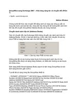
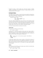
The RTC (Real Time Clock) unit is a peripheral device inside the S3C44B0X. The function diagram is shown in
Figure 4-12. The backup battery can operate the RTC (Real Time Clock) unit while the system power is off. The
RTC can transmit 8-bit data to CPU as BCD (Binary Coded Decimal) values using the STRB/LDRB ARM
operation. The data include second, minute, hour, date, day, month, and year. The RTC unit works with an
external 32.768 KHz crystal and also can perform the alarm function.
Figure 4-12 S3CEV40 RTC Module Function Diagram
The following are the features of the RTC (Real Time Clock) unit:
● BCD number: second, minute, hour, date, day, month, year
● Leap year generator
● Alarm function: alarm interrupt or wake-up from power down mode.
● Year 2000 problem is removed.
● Independent power pin (VDDRTC)
● Supports millisecond tick time interrupt for RTOS kernel time tick.
● Round reset function
1) Read/Write Registers
Bit 0 of the RTCCON register must be set in order to read and write the register in RTC block. To display the
sec., min., hour, date, month, and year, the CPU should read the data in BCDSEC, BCDMIN, BCDHOUR,
BCDDAY, BCDDATE, BCDMON, and BCDYEAR registers, respectively, in the RTC block. However, a one
second deviation may exist because multiple registers are read. For example, suppose that the user reads the
registers from BCDYEAR to BCDMIN, and the result is is 1959(Year), 12(Month), 31(Date), 23(Hour) and
Embedded Systems Development and Labs; The English Edition
178
59(Minute). If the user reads the BCDSEC register and the result is a value from 1 to 59(Second), there is no
problem, but, if the result is 0 sec., the year, month, date, hour, and minute may be changed to 1960(Year),
1(Month), 1(Date), 0(Hour) and 0(Minute) because of the one second deviation that was mentioned. In this case
(when BCDSEC is zero), the user should re-read from BCDYEAR to BCDSEC.
2) Backup Battery Operation
The RTC logic can be driven by the backup battery, which supplies the power through the RTCVDD pin into
RTC block, even if the system’s power is off. When the system is off, the interfaces of the CPU and RTC logic
are blocked, and the backup battery only drives the oscillator circuit and the BCD counters in order to minimize
power dissipation.
3) Alarm Function
The RTC generates an alarm signal at a specified time in the power down mode or normal operation mode. In
normal operation mode, the alarm interrupt (ALMINT) is activated. In the power down mode the power
management wakeup (PMWKUP) signal is activated as well as the ALMINT. The RTC alarm register,
RTCALM, determines the alarm enable/disable and the condition of the alarm time setting.
4) Tick Time Interrupt
The RTC tick time is used for interrupt request. The TICNT register has an interrupt enable bit and the count
value for the interrupt. The count value reaches '0' when the tick time interrupt occurs. Then the period of
interrupt is as follow:
Period = (n+1 ) / 128 second
n : Tick time count value (1-127)
This RTC time tick may be used for RTOS (real time operating system) as kernel time tick. If the RTC is used to
generate the time ticks, the time related function of RTOS would always be synchronized in real time.
5) Round Reset Function
The round reset function can be performed by the RTC round reset register, RTCRST. The round boundary (30,
40, or 50 sec) of the second carry generation can be selected, and the second value is rounded to zero in the
round reset. For example, when the current time is 23:37:47 and the round boundary is selected to 40 sec, the
round reset changes the current time to 23:38:00.
NOTE 1: All RTC registers have to be accessed by the byte unit using the STRB, LDRB instructions or char
type pointer.
NOTE 2: For a complete description of the registers bits please check the “S3C44BOX User’s Manual”.
4.5.5 Lab Design
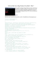
1. Hardware Circuit Design
The real-time peripheral circuit is shown in Figure 4-13.
Embedded Systems Development and Labs; The English Edition
179
R72
10K
C54
104
BAT1
BATTERY
D9
1N4148
VDDRTC
VDD33
GND
C47
15P
C46
15P
X2
CRYSTAL
GND
EXTAL1
XTAL1
32.768k
Figure 4-13 Real-Time Peripheral Circuit
2. Software Design
1) Timer Settings
The timer setting program implements functions such as detecting timer work status, verifying the setup data.
For detailed implementations, please refer to Section 4.5.7 “Timer Setting Control Program” and to the
“S3C44BOX User’s Manual”.
2) Time Display
The time parameters are transferred through the serial port 0 to the hyper terminal. The display content includes
year, month, day, hour, minute, second. The parameters are transferred as BCD code. The users can use the
serial port communication program (refer to Section 4.4 “Serial Port Communication Lab”) to transfer the time
parameters.
The following presents the C code of the RTC display control program:
void Display_Rtc(void)
{
Read_Rtc();
Uart_Printf(" Current Time is %02x-%02x-%02x %s",year,month,day,date[weekday]);
Uart_Printf(" %02x:%02x:%02x\r",hour,min,sec);
}
void Read_Rtc(void)
{
//Uart_Printf("This test should be excuted once RTC test(Alarm) for RTC initialization\n");
rRTCCON = 0x01; // R/W enable, 1/32768, Normal(merge), No reset
while(1)
{
Embedded Systems Development and Labs; The English Edition
180
if(rBCDYEAR == 0x99)
year = 0x1999;
else
year = 0x2000 + rBCDYEAR;
month=rBCDMON;
day=rBCDDAY;
weekday=rBCDDATE;
hour=rBCDHOUR;
min=rBCDMIN;
sec=rBCDSEC;
if(sec!=0)
break;
}
rRTCCON = 0x0; // R/W disable(for power consumption), 1/32768, Normal(merge), No reset
}
4.5.6 Operation Steps
1) Prepare the Lab environment. Connect the Embest Emulator to the target board. Connect the target board
UART0 to PC serial port using the serial cable that comes with the Embest development system.
2) Run the PC Hyper Terminal (set to 115200 bits per second, 8 data bits, none parity, 1 stop bits, none flow
control).
3) Connect the Embest Emulator to the target board. Open the RTC_test.ews project file located
in …\EmbestIDE\Examples\Samsung\S3CEV40\RTC_test directory. After compiling and linking, connect to
the target board and download the program.
(4) Watch the main window of the hyper terminal, the following information is shown:
RTC Working now. To set time (Y/N)?: y
(5) User can select “y” for timer settings. When a wrong item is introduced, a prompt will ask to input it again.
The prompt information is as following:
Current day is (200d, 1e, 27, TUE). To set day (yy-mm-dd w):
2003-11-07 5
Current time is (1f:08:18). To set time (hh : mm : ss) : 15 : 10 : 00
(6) At last the hyper terminal will display:
2003,11,07,FRI
15:10:14
(7) After understanding and learning the contents of the lab perform the Lab exercises.
4.5.7 Sample Programs
1. Environments and Function Declare
char RTC_ok;
int year;
int month,day,weekday,hour,min,sec;
Embedded Systems Development and Labs; The English Edition
181
int Test_Rtc_Alarm(void);
void Rtc_Init(void);
void Read_Rtc(void);
void Display_Rtc(void);
void Test_Rtc_Tick(void);
void Rtc_Int(void) __attribute__ ((interrupt ("IRQ")));
void Rtc_Tick(void) __attribute__ ((interrupt ("IRQ")));
2. Time Tick Control Program
void Test_Rtc_Tick(void)
{
pISR_TICK=(unsigned)Rtc_Tick;
rINTMSK=~(BIT_GLOBAL|BIT_TICK);
sec_tick=1;
rTICINT = 127+(1<<7); //START
}
void Rtc_Tick(void)
{
rI_ISPC=BIT_TICK;
Uart_Printf("\b\b\b\b\b\b\b%03d sec",sec_tick++);
}
3. Timer Configuration Control Program
char check_RTC(void)
{
char RTC_alr = 0;
/* //check RTC code
char yn = 0x59;
while((yn ==0x0d)|(yn ==0x59)|(yn ==0x79)|(RTC_alr ==0))
{
Uart_Printf("\n RTC Check(Y/N)? ");
yn = Uart_Getch();
if((yn == 0x4E)|(yn == 0x6E)|(yn == 0x59)|(yn == 0x79)) Uart_SendByte(yn);
if((yn == 0x0d)|(yn == 0x59)|(yn == 0x79))
{
RTC_alr = Test_Rtc_Alarm();
Display_Rtc();
}
else break;
Embedded Systems Development and Labs; The English Edition
182
if (RTC_alr) break;
}
*/
RTC_alr = Test_Rtc_Alarm();
Display_Rtc();
return RTC_alr;
}
char USE_RTC(void)
{
char yn,tmp,i,N09=1;
char num0 = 0x30;//"0";
char num9 = 0x39;//"9";
char schar[] ={0,'-',' ',':'};
char sDATE[12];//xxxx-xx-xx x
char sTIME[8];//xx:xx:xx
if(check_RTC())
{
Uart_Printf("\n RTC Working now. To set time(Y/N)? ");
yn = Uart_Getch();
if((yn == 0x4E)|(yn == 0x6E)|(yn == 0x59)|(yn == 0x79)) Uart_SendByte(yn);
if((yn == 0x0d)|(yn == 0x59)|(yn == 0x79)) //want to set time?
{
///////////////////////////////////////////////////////////////////////////////////
do{
Uart_Printf("\nCurrent day is (%04x,%02x,%02x, %s). To set day(yy-mm-dd w): "\
,year,month,day,date[weekday]);
Uart_GetString(sDATE);
if(sDATE[0] == 0x32)
{
if((sDATE[4] == schar[1] )&(sDATE[7] == schar[1] )&(sDATE[10] == schar[2] ))
{
if((sDATE[11] >0)|(sDATE[11] <8))
{
i=0; N09 = 0;
while(i<12)
{
if((i !=4)|(i !=7)|(i !=10))
{
if((sDATE[i] < num0 )&(sDATE[i] > num9))
Embedded Systems Development and Labs; The English Edition
183
{ N09 = 1;
break; }
}
i++;
}
if(N09 == 0)
break;//all right
} // if date 1 - 7
} // if "-" or " "
} // if 32 (21th century)
N09 = 1;
Uart_Printf("\n Wrong value!! To set again(Y/N)? ");
yn = Uart_Getch(); //want to set DATE again?
if((yn == 0x4E)|(yn == 0x6E)|(yn == 0x59)|(yn == 0x79)) Uart_SendByte(yn);
}while((yn == 0x0d)|(yn == 0x59)|(yn == 0x79));
if(N09 ==0)
{
rRTCCON = 0x01; // R/W enable, 1/32768, Normal(merge), No reset
rBCDYEAR = ((sDATE[2]<<4)|0x0f)&(sDATE[3]|0xf0);//->syear;
rBCDMON = ((sDATE[5]<<4)|0x0f)&(sDATE[6]|0xf0);//->smonth;
rBCDDAY = ((sDATE[8]<<4)|0x0f)&(sDATE[9]|0xf0);//->sday;
tmp = ((sDATE[11]&0x0f)+1);
if(tmp ==8) rBCDDATE = 1;// SUN:1 MON:2 TUE:3 WED:4 THU:5 FRI:6 SAT:7
else rBCDDATE = tmp;
rRTCCON = 0x00; // R/W disable
}else Uart_Printf("\n\n Use Current DATE Settings.\n");
///////////////////////////////////////////////////////////////////////////////////
do{
Uart_Printf("\nCurrent time is (%02x:%02x:%02x). To set time(hh:mm:ss): "\
,hour,min,sec);
Uart_GetString(sTIME);
if((sTIME[2] == schar[3] )&(sTIME[5] == schar[3]))
{
i=0; N09 = 0;
while(i<8)
{
if((i !=2)|(i !=5))
{
if((sTIME[i] < num0 )&(sTIME[i] > num9))
{ N09 = 1;
Embedded Systems Development and Labs; The English Edition
184
break; }
}
i++;
}
if(N09 == 0)
{
tmp = ((sTIME[0]<<4)|0x0f)&(sTIME[1]|0xf0);
if((tmp >0)&(tmp <0x24))
{
sTIME[2] = tmp;//->shour;
tmp = ((sTIME[3]<<4)|0x0f)&(sTIME[4]|0xf0);
if(tmp <=0x59)
{
sTIME[5] = tmp;//->smin;
tmp = ((sTIME[6]<<4)|0x0f)&(sTIME[7]|0xf0);
if(tmp <=0x59)
break;//all right
} //if min < 59
} //if 0 < hour < 24
} //if num 0-9
}
N09 = 1;
Uart_Printf("\n Wrong value!! To set again(Y/N)? ");
yn = Uart_Getch(); //want to set Time again?
if((yn == 0x4E)|(yn == 0x6E)|(yn == 0x59)|(yn == 0x79)) Uart_SendByte(yn);
}while((yn == 0x0d)|(yn == 0x59)|(yn == 0x79));
if(N09 ==0)
{
rRTCCON = 0x01; // R/W enable, 1/32768, Normal(merge), No reset
rBCDHOUR = sTIME[2]; //->shour;
rBCDMIN = sTIME[5]; //->smin;
rBCDSEC = ((sTIME[6]<<4)|0x0f)&(sTIME[7]|0xf0); //->ssec;
rRTCCON = 0x00; // R/W disable
}else Uart_Printf("\n\n Use Current TIME Settings.\n");
}else{
Uart_Printf("\n Use Current Settings \n");
return 1;
} /* end if want to set? */
}else{
Uart_Printf("\n Please check RTC or maybe it's Wrong. \n");
Embedded Systems Development and Labs; The English Edition
185
return 0;
} /* end if(check_RTC) */
}
4.5.8 Exercises
Write a program detecting RTC clock (alarm) function.
4.6 8-SEG LED Display Lab
4.6.1 Purpose
● Get familiar with LED display and its control method.
● Get better understanding of the memory access principles presented in the Section 4.1 Lab.
4.6.2 Lab Equipment
● Hardware: Embest S3CEV40 hardware platform, Embest Standard/Power Emulator, PC.
● Software: Embest IDE 2003, Windows 98/2000/NT/XP operation system.
4.6.3 Content of the Lab
Write a program that displays 0-9, A-F to the 8-SEG LED.
4.6.4 Principles of the Lab
1. 8-SEG LED
In embedded system, the 8-SEG LED is often used to display digitals and characters. The 8-SEG LED displays
are simple and durable and offer clear and bright displays at low voltage.
1) Architecture
The 8-SEG LED consists of 8 irradiant diodes. 8-SEG LED can display all the numbers and part of English
characters.
2) Types
The 8-SEG LED displays are of two types. One is the common anode type where all the anodes are connected
together and the other is the common cathode type where all the cathodes are connected together.
3) Work Principles
Using the common anode type, when the control signal for one segment is low, the related LED will be lit.
When a character needs to be displayed, a combination of LEDs must be on. Using the common cathode type,
the LED will be on when the control signal is high.
The following is the commonly used character segment coding:
Embedded Systems Development and Labs; The English Edition
186
a
bf
c
g
d
e
DPY
VCC
1
a
2
b
3
c
4
d
5
VCC
6
f
9
g
10
dp
e
8
dp
7
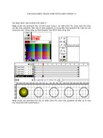
Figure 4-14. 8-Segment LED
Table 4-28 Common Used Character Segment Coding
Character
dp g f e d c b a Common
Cathode
Common
Anode
0
0 0 1 1 1 1 1 1 3FH C0H
1
0 0 0 0 0 1 1 0 06H F9H
2
0 1 0 1 1 0 1 1 5BH A4H
3
0 1 0 0 1 1 1 1 4FH B0H
4
0 1 1 0 0 1 1 0 66H 99H
5
0 1 1 0 1 1 0 1 6DH 92H
6
0 1 1 1 1 1 0 1 7DH 82H
7
0 0 0 0 0 1 1 1 07H F8H
8
0 1 1 1 1 1 1 1 7FH 80H
9
0 1 1 0 1 1 1 1 6FH 90H
A
0 1 1 1 0 1 1 1 77H 88H
B
0 1 1 1 1 1 0 0 7CH 83H
C
0 0 1 1 1 0 0 1 39H C6H
D
0 1 0 1 1 1 1 0 5EH A1H
E
0 1 1 1 1 0 0 1 79H 86H
F
0 1 1 1 0 0 0 1 71H 8EH
–
0 1 0 0 0 0 0 0 40H BFH
.
1 0 0 0 0 0 0 0 80H 7FH
Extinguishes
0 0 0 0 0 0 0 0 00H FFH
NOTE: dp – decimal point
4) Display Method
The 8-SEG LED has two ways of displaying and these are static and dynamic.
Embedded Systems Development and Labs; The English Edition
187
Static Display: When the 8 SEG LED displays a character, the control signals remain the same.
Dynamic Display: When the 8 SEG LED displays a character, the control signals are alternately changing. The
control signal is valid in a period of time (1 ms). Because of the human’s eyes vision, the display of LEDs
appears stable.
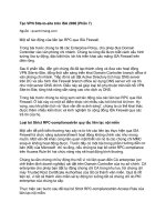
2. Principles of Circuits
In the circuit of S3CEV40, common anode type of 8-SEG is used. The control signals for each segment are
controlled by lower 8 bits of S3C44B0 data bus through 74LS573 flip-latch. The resisters R1-R8 can modify the
brightness of the LED. The chip selection for the 74LS573 flip-latch is shown in Figure 4-15.
The flip-latch chip select signal CS6 is generated by S3C44B0 nGCS1 and A18, A19, A20. Shown in Figure
4-16. When nGCS1, A18, A20 are high, and A19 is low, the CS6 is valid. At this time the contents in the lower 8
bits of data bus will be displayed at the 8-SEG LED.
a
bf
c
g
d
e
DPY
VCC
1
a
2
b
3
c
4
d
5
VCC
6
f
9
g
10
dp
e
8
dp
7
U1
8-LED
VDD33
OE
1
D0
2
D1
3
D2
4
Q2
17
Q1
18
Q0
19
VCC
20
D3
5
D4
6
D5
7
D6
8
Q6
13
Q5
14
Q4
15
Q3
16
D7
9
GND
10
G
11
Q7
12
U2
74LS573
VDD33
D0
D1
D2
D3
D4
D5
D6
D7
CS6
R7
470E
R5
470E
R8
470E
R6
470E
R4
470E
R2
470E
R3
470E
R1
470E
56
U8C
74HC14
GND
GND
Figure 4-15 8-SEG LED Control Circuit
A0
1
A1
2
A2
3
S3
4
S2
5
S1
6
Y7
7
VSS
8
Y2
13
Y1
14
Y0
15
VDD
16
Y6
9
Y5
10
Y4
11
Y3
12
U7
74LV138
R35
22E
V
DD33
A20
A19
nGCS1
GND
A18
CS1
R32
10K
CS2
CS8
CS3
CS7
CS4
VDD33
CS5
CS6
Figure 4-15 S3CEV40 Chip Select Signal Decode Circuit
Embedded Systems Development and Labs; The English Edition
188
The start address and end address of the S3C44B0 storage area 1 is fixed. The address range of storage area 1 is
0x02000000-0x2FFFFFF. When the microprocessor accesses this area, the nGCS1 is valid. Compound with
A18, A19, A20, CS6 will be valid when the microprocessor accesses the address 0x02140000-0x0217FFFF. In
the program, the 8SEG LED is displayed by sending data to the address 0x02140000.
4.6.5 Operation Steps
(1) Prepare the Lab environment. Connect the Embest Emulator to the target board. Connect the target board
UART0 to PC serial port using the serial cable that comes with the Embest development system.
2) Run the PC Hyper Terminal (set to 115200 bits per second, 8 data bits, none parity, 1 stop bits, none flow
control).
3) Connect the Embest Emulator to the target board. Open the RTC_test.ews project file located
in …\EmbestIDE\Examples\Samsung\S3CEV40\8LED_test directory. After compiling and linking, connect to
the target board and download the program.
(4) The hyper terminal should output the following messages:
Embest 44B0X Evaluation Board (S3CEV40)
8-segment Digit LED Test Example (Please look at LED)
(5) The lab system 8-SEG LED will display 0-F alternately.
(6) After understanding and learning the contents of the lab perform the Lab exercises.
4.6.6 Sample Programs
/* macro defines */
/* Bitmaps for 8-segment */
#define SEGMENT_A 0x80
#define SEGMENT_B 0x40
#define SEGMENT_C 0x20
#define SEGMENT_D 0x08
#define SEGMENT_E 0x04
#define SEGMENT_F 0x02
#define SEGMENT_G 0x01
#define SEGMENT_P 0x10
#define DIGIT_F (SEGMENT_A | SEGMENT_G | SEGMENT_E | SEGMENT_F)
#define DIGIT_E (SEGMENT_A | SEGMENT_G | SEGMENT_E | SEGMENT_F | SEGMENT_D)
#define DIGIT_D (SEGMENT_B | SEGMENT_C | SEGMENT_D | SEGMENT_F | SEGMENT_E)
#define DIGIT_C (SEGMENT_A | SEGMENT_D | SEGMENT_E | SEGMENT_G)
#define DIGIT_B (SEGMENT_C | SEGMENT_D | SEGMENT_F | SEGMENT_E | SEGMENT_G)
#define DIGIT_A (SEGMENT_A | SEGMENT_B | SEGMENT_C | SEGMENT_F | SEGMENT_E |
SEGMENT_G)
#define DIGIT_9 (SEGMENT_A | SEGMENT_B | SEGMENT_C | SEGMENT_F | SEGMENT_G)
#define DIGIT_8 (SEGMENT_A | SEGMENT_B | SEGMENT_C | SEGMENT_D | SEGMENT_F |
Embedded Systems Development and Labs; The English Edition
189
SEGMENT_E | SEGMENT_G)
#define DIGIT_7 (SEGMENT_A | SEGMENT_B | SEGMENT_C)
#define DIGIT_6 (SEGMENT_A | SEGMENT_C | SEGMENT_D | SEGMENT_F | SEGMENT_E |
SEGMENT_G)
#define DIGIT_5 (SEGMENT_A | SEGMENT_C | SEGMENT_D | SEGMENT_F | SEGMENT_G)
#define DIGIT_4 (SEGMENT_B | SEGMENT_C | SEGMENT_F | SEGMENT_G)
#define DIGIT_3 (SEGMENT_A | SEGMENT_B | SEGMENT_C | SEGMENT_D | SEGMENT_F)
#define DIGIT_2 (SEGMENT_A | SEGMENT_B | SEGMENT_D | SEGMENT_E | SEGMENT_F)
#define DIGIT_1 (SEGMENT_B | SEGMENT_C)
#define DIGIT_0 (SEGMENT_A | SEGMENT_B | SEGMENT_C | SEGMENT_D | SEGMENT_E |
SEGMENT_G)
/* 8led control register address */
#define LED8ADDR (*(volatile unsigned char *)(0x2140000))
/********************************************************************
* name: Digit_Led_Test
* func: 8-segment digit LED test function
*********************************************************************/
void Digit_Led_Test(void)
{
int i;
/* display all digit from 0 to F */
for( i=0; i<16; i++ )
{
Digit_Led_Symbol(i);
Delay(4000);
}
}
4.6.7 Exercises
Write a program that displays each segment of the 8-SEG LED alternatively.
Embedded Systems Development and Labs; The English Edition
190
Chapter 5 Human Interface Labs
5.1 LCD Display Lab
5.1.1 Purpose
● Learn to use the LCD panel and understand its circuit functionality.
● Learn to program the S3C44B0X LCD controller.
● Through the Lab, learn to displaying text and graphic on the LCD.
5.1.2 Lab Equipment
● Hardware: Embest S3CEV40 hardware platform, Embest Standard/Power Emulator, PC.
● Software: Embest IDE 2003, Windows 98/2000/NT/XP operation system.
5.1.3 Content of the Lab
Learn to use the S3CEV40 16 Gray Scale LCD panel (320 x 240 pixels) controller. Understand the human
interface programming methods based on the LCD display.
● Draw multiple rectangles.
● Display ASCII characters.
● Display a mouse bitmap.
5.1.4 Principles of the Lab
1. LCD Panel
LCD (Liquid Crystal Display) is mainly used in displaying text and graphic information. The LCD device is
highly popular for human interface development due the fact that the device is thin, small size, low power, no
radiation, etc.
1) Main types of LCD and Parameters
(1) STN LCD Panel
The STN (Super Twisted Nematic) LCD panel displays in light green or orange color. STN LCD panel is a type
of liquid crystal whereas the alignment surface and therefore the LC molecules are oriented 90° from each
surface of glass. This device produces images in two modes: Positive and Negative. Positive Mode provides
white background with black segments. Negative Mode provides black background and white segments. When
two polarizing filters are arranged along perpendicular axes, as in the first illustration, light passes through the
lead filter and follows the helix arrangement of the liquid crystal molecules. The light is twisted 90 degrees, thus
allowing it to pass through the lower filter. When voltage is applied, however, the liquid crystal molecules
straighten out of their helix pattern. Light is blocked by lower filter and the screen appears black because of
there being no twisting effect.
(2)
TFT Color LCD Panel
TFT (Thin Film Transistor) color LCD panels are widely used in computers like notebook computers and
monitors.
Embedded Systems Development and Labs; The English Edition
191
The main parameters of LCD are size, differentiate, dot width and color mode, etc. The mian parameters of
S3C40 development board LCD panel (LRH9J515XA STN/BW) are shown in Table 5-1.
The size parameters are shown in Figure 5-1. The outlook is shown is Figure 5-2.
Figure 5-1 Size Parameters (The unit of the numbers are mm)
Table 5-1 LRH9J515XA STN/BW LCD Panel Main Parameters
Model
LRH9J515XA
External
Dimension
93.8×75.1×5mm
Weight
45g
Picture
Element
320 × 240
Picture Size
9.6cm 3.8inch
Color
16 Level
gradation
Voltage
21.5V
25
Width
0.24 mm/dot
Attach
ment
Cable
connected
Embedded Systems Development and Labs; The English Edition
192
Figure 5-2 LRH9J515XA STN/BW
2) Driver and Display
LCD panel has specific driver circuitry. The driver circuit provides power, lamp voltage and LCD driver logic.
The display control circuit can be a separate IC unit such as EPSON LCD drivers, etc or the LCD driver can be
an internal module of the microprocessor. The Embest development board uses the on-chip S3C44B0X LCD
module that includes the LCD controller, the LCD driver logic and its peripheral circutry.
2. S3C44B0X LCD Controller (See the “S3C44BOX User’s Manual” for a complete description)
S3C44B0X integrated LCD controller supports 4-bit Single Scan Display, 4-bit Dual Scan Display and 8-bit
Single Scan Display. The on-chip RAM is used as display buffer and supports screen scrolling. DMA (direct
memory access) is used in data transfer for minimum delay. Programming according to the hardware could
enable the on-chip LCD controller to support many kinds of LCD panels. The LCD controller within the
3C44B0X is used to transfer the video data and to generate the necessary control signals. The LCD controller
block diagram is shown in Figure 5-3.
Figure 5-3 LCD Controller Block Diagram
1) LCD Controller Interface
The following describes the external LCD interface signals that are commonly used:
• VFRAME: this is the frame synchronous signal between the LCD controller and the LCD driver. It
signals the LCD panel of the start of a new frame. The LCD controller asserts VFRAME after a full
Embedded Systems Development and Labs; The English Edition
193
frame of display as shown if Figure 5-4.
• VLINE: This is the line synchronization pulse signal between the LCD controller and the LCD driver,
and it is used by the LCD driver to transfer the contents of its horizontal line shift register to the LCD
panel for display. The LCD controller asserts VLINE after an entire horizontal line of data has been
shifted into the LCD driver.
• VCLK: This pin is the pixel clock signal between the LCD controller and the LCD driver, and data is
sent by the LCD controller on the rising edge of the VCLK and is sampled by the LCD driver on the
falling edge of the VCLK.
• VM: This is the AC signal for the LCD driver. The VM signal is used by the LCD driver to alternate
the polarity of the row and column voltage used to turn the pixel on and off. The VM signal can be
toggled on every frame or toggled on the programmable number of the VLINE signal.
• VD[3:0]: This is the LCD pixel data output port. It is used for monochrome displays.
• VD[7:0]: This is the LCD pixel data output port. It is used for monochrome and color displays.
2) LCD Controller Time Sequence
The LCD Controller Time Sequence is shown is Figure 5-4.
Figure 5-4 LCD Controller Time Sequence
3) Supported Scan Modes
The scan mode of S3C44B0X LCD controller can be set through DISMOD(LCDCON1[6:5]). The selection of
scan mode is shown in Table 5-3.
DISMOD[6:5] 00 01 10 11
Mode display
4-bit dual
scan
4-bit single
scan
8-bit single
scan
Not used
Table 5-3 Scan Mode Selections
(1) 4-bit Single Scan – the LCD controller scan line is started from the left-top corner of the LCD panel. The
displayed data is VD[3:0]. The correspondence between the VD bits and the RGB color digits is shown in
Figure 5-5.
Embedded Systems Development and Labs; The English Edition
194
Figure 5-5 4-bit Single Scan
(2) 4-bit Dual Scan
The LCD controller uses two scan lines for data display. The higher scan display data is available from VD[3:0].
The lower scan display data is available from VD[7:4]. The correspondence between the VD bits and the RGB
color digits is shown in Figure 5-6.
Figure 5-6 4-bit Dual Scan
(3) 8-bit Single Scan – the LCD controller scan line is started from the left-top corner of the LCD panel. The
displayed data is VD[7:0]. The correspondence between the VD bits and the RGB color digits is shown in
Figure 5-7.
Figure 5-7 8-bit Single Scan
Embedded Systems Development and Labs; The English Edition
195
4) Data Storage and Display
The data transferred by LCD controller represent the attribute of a pixel. 4 gray scale screens use 2 bits data. 16
gray scale screens use 4 bits data. Color RGB screen uses 8 bits data (R[7:5], G[4:2],B[1:0]). The data stored in
the display buffer should meet the configuration requirement of hardware and software, specifically, the length
of data. The data storage of 4-bit Single Scan and 8-bit Single Scan are shown in Figure 5-8. The data storage of
4-bit Dual Scan is shown in Figure 5-9.
Figure 5-8 4-bit Single Scan and 8-bit Single Scan
Figure 5-9 4-bit Dual Scan
In 4-level gray mode, 2 bits of video data correspond to 1 pixel.
In 16-level gray mode, 4 bits of video data correspond to 1 pixel.
In color mode, 8 bits (3 bits of red, 3 bits of green, 2 bits of blue) of video data correspond to 1 pixel. The color
data format in a byte is as follows:
Bit[7:5] – Red; Bit[4:2] – Green; Bit[1:0] – Blue.
5) LCD Controller Registers
The S3C44B0X has all together 18 registers. Shown in Table 5-4.
Table 5-4 LCD Controller Registers List
Embedded Systems Development and Labs; The English Edition
196
Embedded Systems Development and Labs; The English Edition
197
The following description is just a simple introduction to these registers. For detailed usage information, please
refer to the S3C44B0X User’s Manual.
6) LCD Controller Main Parameter Settings
In order to use the LCD controller, 18 registers must be configured. The control signal VFRME, VCLK, VLINE
and VM can be configured by the control register LCDCON1/2. For the LCD screen display, control and data
read/write, the other registers should be configured. The details are as following:
(1) Configuration of the VM, VFRAME, VLINE signals
The VM signal is used by the LCD driver to alternate the polarity of the row and column voltage used to turn the
pixel on and off. The toggle rate of VM signal can be controlled by using the MMODE bit of LCDCON 1
register and MVAL [7:0] field of LCDSADDR 2 register, as shown below:
VM Rate = VLINE Rate / (2 * MVAL)
The VFRAME and VLINE pulse generation is controlled by the configurations of the HOZVAL field and the
LINEVAL field in the LCDCON2 register. This is shown below:
HOZVAL = (Horizontal display size / Number of the valid VD data line) -1
In color mode:
Horizontal display size = 3 * Number of Horizontal Pixel
LINEVAL = (Vertical display size) -1: In case of single scan display type
LINEVAL = (Vertical display size / 2) -1: In case of dual scan display type
(2) Configuration of the VCLK signal
VCLK is the timer signal of the LCD. When the processor is working at MCLK = 66MHz, the highest
frequency of VCLK is 16.5MHz. The minimum value of CLKVAL is 2.
VCLK(Hz)=MCLK/(CLKVAL x 2)
The frame rate is given by the VFRAM signal frequency. The frame rate is closely related to the field of WLH
(VLINE pulse width), WHLY (the delay width of VCLK after VLINE pulse), HOZVAL, VLINEBLANK, and
LINEVAL in LCDCON1 and LCDCON2 registers as well as VCLK and MCLK. Most LCD drivers need their
own adequate frame rate. The frame rate is calculated as follows:
frame_rate(Hz) = 1 / [ ( (1/VCLK) x (HOZVAL+1)+(1/MCLK) x (WLH+WDLY+LINEBLANK) ) x
( LINEVAL+1) ]
VCLK(Hz) = (HOZVAL+1) / [ (1 / (frame_rate x (LINEVAL+1))) - ((WLH+WDLY+LINEBLANK) / MCLK )]
Embedded Systems Development and Labs; The English Edition
198
Table 5-5 Relation between VCLK and CLKVAL(MCLK=60MHz)
(3) Dada Frame Display Control Settings
• LCDBASEU: These bits indicate A[21:1] of the start address of the upper address counter, which is for
the upper frame memory of dual scan LCD or the frame memory of single scan LCD.
• LCDBASEL: These bits indicate A[21:1] of the start address of the lower address counter, which is
used for the lower frame memory of dual scan LCD.
• LCDBASEL = LCDBASEU + (PAGEWIDTH + OFFSIZE) x (LINEVAL +1)
• PAGEWIDTH: Virtual screen page width (the number of half words) this value defines the width of the
view port in the frame
• OFFSIZE: Virtual screen offset size (the number of half words). This value defines the difference
between the address of the last half word displayed on the previous LCD line and the address of the first
half word to be displayed in the new LCD line.
• LCDBANK: These bits indicate A[27:22] of the bank location for the video buffer in the system
memory. LCDBANK value cannot be changed even when moving the view port.
7) Gray Mode Operation
Two gray modes are supported by the LCD controller within the S3C44B0X: 2-bit per pixel gray (4 level gray
scale) or 4-bit per pixel gray (16 level gray scale). The 2-bit per pixel gray mode uses a lookup table, which
allows selection on 4 gray levels among 16 possible gray levels. The 2-bit per pixel gray lookup table uses the
BULEVAL[15:0] in BLUELUT(Blue Lookup Table) register as same as blue lookup table in color mode. The
gray level 0 will be denoted by BLUEVAL[3:0] value. If BLUEVAL[3:0] is 9, level 0 will be represented by
gray level 9 among 16 gray levels. If BLUEVAL[3:0] is 15, level 0 will be represented by gray level 15 among
16 gray levels, and so on. As same as in the case of level 0, level 1 will also be denoted by BLUEVAL[7:4], the
level 2 by BLUEVAL[11:8], and the level 3 by BLUEVAL[15:12]. These four groups among BLUEVAL[15:0]
will represent level 0, level 1, level 2, and level 3. In 16 gray levels, of course there is no selection as in the 4
gray levels.
When the Embest S3CEV40 development board uses 16-level gray scale screen, the LCD controller parameter
setting can apply the following two rules:
(1) LCD Panel: 320 x 240, 16 gray scale, single scan mode
Data frame start address = 0xC300000, offset dot numbers=2048 (512 half words)
Parameter setting is as following:
LINEVAL = 240 –1 = 0xEF;
PAGEWIDTH = 320 x 4/16 = 0x50;
OFFSIZE = 512 = 0x200;
Embedded Systems Development and Labs; The English Edition
199
LCDBANK = 0xc300000 >> 22 = 0x30;
LCDBASEU = 0x100000 >> 1 = 0x8000;
LCDBASEL = 0x8000 + (0x50 + 0x200) x (0xef + 1) = 0xa2b00;
(2) LCD Panel: 320 x 240, 16 gray scale, dual scan mode
LINEVAL = 120 –1 = 0x77;
PAGEWIDTH = 320 x 4/16 = 0x50;
OFFSIZE = 512 = 0x200;
LCDBANK = 0xc300000 >> 22 = 0x30;
LCDBASEU = 0x100000 >> 1 = 0x8000;
LCDBASEL = 0x8000 + (0x50 + 0x200) x (0x77 + 1) = 0xa91580;
5.1.5 Lab Design
1. Circuit Design
The control circuit for LCD panel must provide power supply, bias voltage and LCD control. The S3C44B0X
has its on-chip LCD controller that can drive the LCD panel on the development board. As a result, the control
circuitry must provide the power supply and the bias voltage supply.
1) The Circuit on LCD Panel
The circuit on LCD panel is shown in Figure 5-10.
Figure 5-10 LCD Panel Architecture Diagram
2) Pin Description
The pin description of LCD panel is shown in Table 5-6.
Table 5-6 LCD Panel Pin Descriptions
Embedded Systems Development and Labs; The English Edition
200
3) Control Circuit Design
The power supply of LCD panel is 21.5V. The development board power supply is 3V or 5V. So a voltage
converter is needed. The development board has a MAX629 power management module for LCD panel power
supply. Figure 5-11 shows the S3CEV40 development board power supply and bias voltage supply circuit.