cisco press router security strategies phần 2 potx
Bạn đang xem bản rút gọn của tài liệu. Xem và tải ngay bản đầy đủ của tài liệu tại đây (6.41 MB, 67 trang )
46 Chapter 1: Internet Protocol Operations Fundamentals
CEF Operation
CEF switching is enabled globally using the ip cef global configuration mode command,
after which CEF switching is enabled on all CEF-capable interfaces by default. CEF can be
enabled or disabled on a per-interface basis. CEF must be enabled on the ingress interface
(whereas fast switching is enabled on the egress interface) to CEF switch packets, because
CEF makes the forwarding decision on ingress. Use the interface configuration mode
command ip route-cache cef to enable CEF, or the no version of the same command to
disable CEF on the ingress interface.
IP POS5/0.1 point2point(9)
IP POS5/0.2 point2point(5)
IP FastEthernet0/2 10.82.69.1(11)
IP FastEthernet0/2 10.82.69.82(5)
IP FastEthernet0/2 10.82.69.103(5)
IP FastEthernet0/2 10.82.69.220(5)
R1#
Example 1-4 Displaying CEF FIB Table Information
R1# show ip cef
Prefix Next Hop Interface
0.0.0.0/0 12.0.0.2 Serial4/1
0.0.0.0/32 receive
10.0.0.0/8 10.82.69.1 FastEthernet0/0
10.82.69.0/24 attached FastEthernet0/0
10.82.69.0/32 receive
10.82.69.1/32 10.82.69.1 FastEthernet0/0
10.82.69.82/32 10.82.69.82 FastEthernet0/0
10.82.69.121/32 receive
10.82.69.220/32 10.82.69.220 FastEthernet0/0
10.82.69.255/32 receive
172.0.0.0/30 attached Serial4/1
172.0.0.0/32 receive
172.0.0.1/32 receive
172.0.0.3/32 receive
172.12.12.0/24 attached Loopback12
172.12.12.0/32 receive
172.12.12.12/32 receive
172.12.12.255/32 receive
192.168.100.0/24 172.0.0.2 Serial4/1
224.0.0.0/4 drop
224.0.0.0/24 receive
R1#
Example 1-3 Displaying CEF Adjacency Table Information (Continued)
IP Router Packet Processing Concepts 47
A distributed version of CEF is available for the 7500, 7600, and Cisco 12000 routers.
On the Cisco 12000 GSR, CEF is enabled by default and in fact is the only version of
switching available on that platform although multiple forwarding paths exist within the
router architecture.
Each time a packet is received on a CEF-enabled interface, the CEF process forwards the
packet, as illustrated in Figure 1-13 and explained next:
1 CEF switching begins exactly like the other switching methods. First, the network
interface hardware receives the packet and transfers it into I/O memory. The network
interface interrupts the CPU, alerting it to the ingress packet waiting in I/O memory
for processing. IOS updates its inbound packet counters.
2 The IOS interrupt software inspects the packet header information (encapsulation
type, network layer header, and so forth) and determines that it is an IP packet. Instead
of placing the packet on the input queue for CPU processing, however, the interrupt
software consults the FIB for an entry matching the destination address. If an entry
exists, the interrupt software retrieves the pre-built Layer 2 header information from
the adjacency table, and builds the packet for forwarding. Finally, the interrupt
software alerts the outbound interface.
3 The outbound network interface hardware senses the packet, dequeues it from I/O
memory, and transmits it on to the network.
4 If the destination address is not found in the FIB, instead of reverting to fast switching
and then process switching, CEF simply drops the packet which causes a CPU hit for
the resultant ICMP destination unreachable (type 3) generation. Fast switching has no
visibility into the routing table. It depends on process switching to build the fast cache
on the fly. Thus, fast switching can never assume that if a destination prefix does not
exist in the cache, the packet has an unreachable destination. CEF, however, pre-builds
the FIB based on the routing table. Thus, if no entry exists in the FIB, then a valid
destination prefix never will be found, regardless of switching mechanisms. This is
one of the best features of CEF; no processor load is expended for unresolved
destinations.
48 Chapter 1: Internet Protocol Operations Fundamentals
Figure 1-13 Illustration of CEF Switching
From an IP traffic plane perspective, CEF switching primarily not only helps accelerate the
forwarding of transit data plane traffic, but also performs consistent operations for many
other packet types. This is exactly what is needed for building and running higher-speed
networks with high packet rates. All traffic planes and packet types exist in any network,
not to mention malicious packets. All of these packet types must be handled within the
network, but not all of these packets can be CEF switched. When this is the case, routers
must invoke alternate processing functions, often impacting performance. It is most critical
in networks to classify traffic planes and protect router resources. Let’s take a look at each
traffic plane again from the perspective of CEF switching:
• Data plane: CEF switching operations were developed to speed delivery of data plane
transit traffic. These packets will be CEF switched when a FIB entry exists and will
be dropped when a FIB entry does not exist. Dropping packets with unresolved
destinations gives CEF a tremendous advantage over other switching methods because
no CPU involvement is necessary simply to drop these packets. You should be
aware, however, that dropping these packets does cause the generation of an ICMP
L3
Packet
L3
Packet
L2
Frame
L2
Frame
Input
Queue
Interface
Processor
Interface
Processor
CEF
Switching
Drop Packet
No
Yes
Update
Processing
IP Routing
Table
Output
Queue
CEF Tables
FIB and Adjacency
Entry in
FIB?
Software
Process
Interrupt Processing
IP Router Packet Processing Concepts 49
unreachable error message. On most routers, ICMP packets are generated by the CPU.
Thus, even with CEF switching, some CPU impacts can be seen when high rates of
ICMP unreachable messages are generated. As you will learn in Chapter 4, ICMP
unreachable message generation can be rate-limited or disabled. Preventing spoofed
or malicious packets from abusing the data plane will also help protect router and
network resources. As with other switching methods, additional processing is required
to handle data plane exception packets as well. For example, TTL = 0 packets must be
dropped and reply ICMP error messages must be generated and transmitted. Packets
with IP options may also require additional processing to satisfy the invoked option.
CEF does use special adjacencies to switch these types of packets to the appropriate
handlers, which means the CPU is not involved in the switching portion of the operation.
Nonetheless, the CPU may be required to process these packets after CEF. When the
ratio of exception packets becomes large in comparison to normal transit packets,
router resources can be taxed, potentially affecting network stability. These and other
concepts are explored further in Chapter 2. Chapter 4 explores in detail the concepts
for protecting the data plane.
• Control plane: Control plane packets with transit destinations are CEF switched
exactly like data plane transit packets. Control plane packets with receive destinations
and non-IP exception packets (for example, Layer 2 keepalives, IS-IS, and so on)
are switched by special adjacencies in CEF to the CPU for processing. Additional
resources are consumed to fully process these packets. Thus, regardless of the switching
method invoked, receive and non-IP control plane packets must be processed by the
CPU, potentially causing high CPU utilization. High CPU utilization could affect the
synchronization of CEF tables (for example, when routing table updates must be
computed), resulting in dropped traffic. It is critical to prevent spoofed and other
malicious packets from impacting the control plane, potentially consuming router
resources and disrupting overall network stability. Chapter 5 explores these concepts
in detail.
• Management plane: Management plane packets with transit destinations are CEF
switched exactly like data plane transit packets. Management plane packets with
receive destinations are switched by special adjacencies in CEF to the CPU for
processing. Additional resources are consumed to fully process these packets and
provide the appropriate network management service. Management plane traffic
should not contain IP exception packets (again, MPLS OAM being one exception),
but may contain non-IP (Layer 2) exception packets (generally in the form of CDP
packets). Under normal circumstances, management plane traffic should have little
impact on CPU performance. It is possible that some management actions, such as
conducting frequent SNMP polling or turning on debug operations, or the use of
NetFlow may cause high CPU utilization. High CPU utilization could affect the
synchronization of CEF tables (for example, when routing table updates must be
50 Chapter 1: Internet Protocol Operations Fundamentals
computed), resulting in dropped traffic. Because management plane traffic is handled
directly by the CPU, the opportunity for abuse makes it critical that management
plane security be implemented. Chapter 6 explores these concepts in detail.
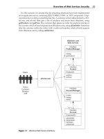
• Services plane: Services plane packets generally require special processing by the
router. Examples include things like performing some encapsulation function (for
example, GRE, IPsec, or MPLS VPN), or performing some QoS or policy routing
function. Some of these operations can be handled by CEF switching and some
cannot. If a feature or encapsulation is not supported in CEF, the packet is passed to
the next switching level (for most routers this would be fast switching), which tries to
switch the packet by using its cache. If it cannot be switched at the interrupt level, the
packet is placed into the IP processing queue for direct CPU handling. CEF fails to
switch packets only because of unsupported features. When this occurs, services
plane packets may have a large impact on CPU utilization. The main concern then is
to protect the integrity of the services plane by preventing spoofed or malicious
packets from impacting the CPU. Chapter 7 explores these concepts in detail.
General IP Router Architecture Types
Now that the main switching methods available in IOS today have been reviewed, and the
impact of various IP traffic planes on their operation and performance has been described,
it is worth looking at the various hardware architectures used in Cisco routers. Although
most Cisco routers implement all of the switching methods described in the previous
section, some do not. In addition, hardware variations lead to different performance levels
for each of the IP traffic planes. Thus, it is important to understand the performance envelop
for each platform inserted in the network. This section gives special attention to the way in
which malicious traffic can affect router hardware architectures.
Increases in performance and the demand for integrated services have driven substantial
changes in router hardware. Most Cisco routers use only one active route processor, even if
more than one is installed. Thus, processing is done in one central location. Some routers
incorporate specialized ASIC hardware to accelerate switching performance. Still others
use distributed hardware architectures to achieve the highest forwarding rates.
The following sections provide general overviews of the basic hardware architectures used
by Cisco routers today. These architectures are covered in sufficient detail to provide a good
understanding of how various IP traffic planes impact their performance. Many excellent
references provide much deeper insights into router architectures. Check the “Further
Reading” section at the end of this chapter for specific recommendations.
Centralized CPU-Based Architectures
The architecture used by the original Cisco routers, and several generations of enterprise-
class routers that have followed, is the centralized CPU-based design. Routers in this
category that you will find in service today include the 800, 1600, 1700, 2500, 2600, 3600,
General IP Router Architecture Types 51
RPM-PR, and 3700 series models. The long-lived 7200 series and the newer 1800, 2800,
and 3800 series Integrated Services Routers (ISR) also use a centralized CPU-based
architecture.
Centralized CPU-based architectures rely on a single CPU to perform all functions required
by the router. This includes such functions as the following:
• Supporting all networking functions, such as running and maintaining routing
protocols and cache states, link states, interfaces and global counters, error packet
(ICMP) generation, and other network control functions
• Supporting all packet forwarding and processing functions, including applying all
services such as access lists, NAT, QoS, and so on as might be applied to packets
during the forwarding process
• Supporting all housekeeping functions, such as servicing configuration and management
functions, including command-line configuration, SNMP and syslog support, and
other device management functions
All of these (and other) functions are handled within Cisco IOS Software. Cisco IOS is a
monolithic operating system; all software modules are statically compiled and linked at
build time, operating in a run-to-completion model within a single address space. In this
kind of model, faults in one function can cause disruptions in other functions. In the
previous section you learned about three different kinds of switching methods, each of
which has different levels of interaction and, hence, impact on the CPU.
A typical centralized CPU-based architecture is shown in Figure 1-14. Advances in bus
architecture, memory size and speed, and CPU processor performance and the addition of
specialty, task-oriented chipsets have led to improvements in overall router performance.
However, even with these advances and additions, centralized CPU-based devices will
always be limited in overall performance given the processing constraints of the CPU-based
architecture.
As illustrated in Figure 1-14, the central CPU provides support for router maintenance
(CLI, management functions, and so on), for running the routing protocols, and for
computing the FIB and adjacency tables described in the previous section. The FIB and
adjacency table information is stored in memory attached to the CPU. All packets transiting
the router (in other words, that ingress and egress through various interfaces) are processed
within the CPU interrupt process if CEF is capable of switching the packet. Packets that
cannot be handled by CEF are punted (switched out of the fast path) for direct handling by
the CPU in software processing (slow path). Packets in this group include all receive
packets, which under normal conditions means control plane, management plane traffic,
plus all exception IP and non-IP packets.
Routers in this category are still quite adequate for most small to medium-sized enterprise
locations where low bandwidth but rich, integrated service requirements are found. These
routers represent an excellent trade-off between acceptable performance, application of
integrated services, and cost. Their lack of capacity for high-speed service delivery and
dense aggregation solutions means that other architectures must be explored.
52 Chapter 1: Internet Protocol Operations Fundamentals
Figure 1-14 Centralized CPU-Based Router Architecture
Centralized ASIC-Based Architectures
As network demands increased, CPU-based architectures alone were unable to provide
acceptable performance levels. To overcome this shortcoming, modern centralized CPU-
based platforms began to include forwarding ASICs in the architecture in order to offload
some processing duties from the CPU and improve upon overall device performance. This
category of devices includes the ubiquitous Catalyst 6500 switch family, the Cisco 7600
router family, the Cisco 7300 and RPM-XF PXF-based routers, and the Cisco 10000 Edge
Services Router (ESR) family. You will most frequently find these devices in large-scale
aggregation environments (such as at the service provider network edge), and medium- to
large-scale enterprise and data center environments where large numbers of flows and high
switching rates are common.
Data Plane
Adj.
FIB
Interrupt Level
Data
Plane
….
Flash DRAM
Console
Interface
Processor
Interface
Processor
Interface
Processor
Bus
CPU
….
….
….
….
….
….
Control Plane
OSPF
Management Plane
Process Level
OSPF
User
ISIS IGMP
MPLSBGP
SNMP
SSH
FTP
syslog
CLI
General IP Router Architecture Types 53
Retaining the centralized architecture makes sense when trading off cost, complexity, and
performance. Of course, the single CPU still performs many of the functions described in
the preceding section, such as supporting all networking and housekeeping functions.
The ASIC incorporated into the architecture provides the ability to apply very complex
operations, such as access control lists (ACL), QoS, policy routing, and so on while
maintaining very high-performance forwarding rates. A typical centralized ASIC-based
architecture is shown in Figure 1-15, which illustrates at a high level the Cisco 10000 ESR
forwarding architecture.
The Cisco 10000 ESR forwarding functions shown in Figure 1-15 are carried out in the
Performance Routing Engine (PRE). The PRE includes a central CPU to support router
maintenance (CLI, management functions, ICMP, and so on) and to run the routing
protocols and compute the FIB and adjacency tables. Once the CPU builds these FIB and
adjacency tables, this information is pushed into the Parallel Express Forwarding (PXF)
ASIC structure. All packets transiting the router (in other words, that ingress and egress
through various line cards) are processed by the PXF. The CPU is not involved in forwarding
packets. If other services are configured, such as the application of ACLs, QoS, policy routing,
and so on, they are also configured and applied in the PXF ASIC structures.
Certain packets and features cannot be processed within ASIC architectures. These packets
are punted to the supporting CPU for full processing. Packets falling into this group include
all receive packets, which essentially means all control plane and management plane packets,
and all exception packets. ASICs are designed to perform high-speed operations on a well-
defined set of packets. Buffers, memory allocations, and data operations are designed for
typical packets with 20-byte IP headers, for example. Packets that include IP options in the
header exceed the 20-byte limit, and thus cannot be handled in the ASIC. Packets like these
are punted to the CPU for handling in the slow path, meaning their processing speed is much
slower. Because the ASIC is forwarding packets independently from the CPU, some amount
of punts will not impact the overall platform throughput for normal, transit traffic. However,
when the rate of exceptions becomes large, forwarding performance may be impacted.
IP traffic plane security must be developed with an understanding of how forwarding is
accomplished in this centralized ASIC-based architecture, including a detailed understanding
of how exception packets affect the performance envelop for the platform. The mechanisms
for securing each traffic plane are covered in detail in Section II.
The centralized ASIC-based architecture offers excellent trade-offs between performance,
application of integrated services, and cost. Routers in this category are well suited for their
intended environments. Yet they are not adequate when the very highest throughputs are
required. The centralized nature of any platform limits forwarding rates to the speed of the
single forwarding engine. To achieve even faster forwarding rates, different architectures
must be used, specifically distributed architectures.
54 Chapter 1: Internet Protocol Operations Fundamentals
Figure 1-15 Centralized ASIC-Based Router Architecture
NOTE Centralized ASIC-based routers may have higher performance than certain distributed
CPU-based routers.
Distributed CPU-Based Architectures
Routers used in large-scale networks require not only high packet-forwarding performance,
but also high port densities. High port densities reduce the overall hardware costs, as well
as the operational costs because fewer devices need to be managed. These demands have
constantly driven router architectures to keep pace. Two approaches can be taken to increase
the forwarding speed of a router. The first, which you just learned about, is to retain the
centralized processing approach but increase the CPU speed or add hardware-based (ASIC)
high-speed forwarding engines. This architecture runs into limitations at some point in both
maximum packet-forwarding rates and port density.
Data Plane
Adj.
FIB
ASIC-Based
Data Plane
….
….
….
….
….
….
….
Control Plane
OSPF
Management Plane
Process Level
ISIS IGMP
MPLSBGP
SNMP
SSH
FTP
syslog
CLI
Uplink
FPGA
Performance Routing Engine
Access
FPGA
12X10/100
ASIC
12X10/100
ASIC
10/100 PHY 10/100 PHY
RAC RAC
Framer Framer
Optics Optics
Packet Forwarding
Engine
Route Processor
ASIC-
Based
PXF
Console
RISC 5K
Use
r
BGP
General IP Router Architecture Types 55
The other approach breaks the router into discrete line cards, each capable of supporting a
number of network interfaces, and “distributing” the processing and forwarding functions
out to each line card. In the earlier section on CEF switching, you learned that CEF pre-
computes the FIB and adjacency tables, and then populates the forwarding engine with
these tables. You can see how CEF is ideally suited for a distributed architecture where each
line card has the intelligence to forward packets as they ingress the router. In this case, each
line card is capable of switching packets, bringing the switching function as close to the
packet ingress point as possible. The other component required to complete the distributed
architecture is a high-speed bus or “switching fabric” to connect the line cards into what
logically appears to the routing domain as a single router. Early distributed architecture
systems used CPU-based forwarding engines. These early distributed CPU-based devices
include the Cisco 7500 series routers and early Cisco 12000 Gigabit Switch Router (GSR)
family line cards (in other words, Engine 0 and Engine 1). Figure 1-16 shows the Cisco
7500 router to illustrate the basics of the distributed CPU-based architecture.
Figure 1-16 Distributed CPU-Based Router Architecture
Route Switch Processor (RSP)
FLASH
Fast
Memory
Processor
Memory
CPU
Packet
Memory
….
….
….
….
….
….
….
Control Plane
OSPF
Management Plane
Process Level
IS-IS IGMP
MPLSBGP
SNMP
SSH
FTP
syslog
CLI
Data Plane
Adj.
FIB
IP
Routing
Table
Console
Versatile Interface
Processor (VIP)
DRAM
CPU
PHY
Versatile Interface
Processor (VIP)
DRAM
CPU
PHY
Data Bus
Data Plane
Interrupt
Level
Data
Plane
Adj.
FIB
Data Plane
Interrupt
Level
Data
Plane
Adj.
FIB
User
Us
er
OSP
F
56 Chapter 1: Internet Protocol Operations Fundamentals
As illustrated in Figure 1-16, the Cisco 7500 router includes a central CPU, referred to as
the Route Switch Processor (RSP), which performs all networking and housekeeping
functions, such as maintaining routing protocols, interface keepalives, and so forth. Thus,
all control plane and management plane traffic is handled by the RSP. The 7500 also includes
multiple Versatile Interface Processors (VIP) with port adapters (PA). Using port adapters
not only provides high port density but also adds flexibility in interface type through
modularity. Distributed switching is supported in VIPs by their own CPUs, RAM, and
packet memory. Each VIP runs a specialized IOS image. Two data transfer buses provide
packet transfer capabilities between VIPs (line cards) and the RSP to support high-speed
forwarding. When a PA receives a packet, it copies the packet into the shared memory on
the VIP and then sends an interrupt to the VIP CPU. The VIP CPU performs a CEF lookup,
and then rewrites the packet header. If the egress port is on the same VIP, the packet is
switched directly. If the egress port is on a different VIP, the RSP is not required for packet
processing but does spend CPU time as a bus arbiter for inter-processor communication
while moving packets across the bus. VIPs can support very complex operations, such as
ACLs, QoS, policy routing, encryption, compression, queuing, IP multicasting, tunneling,
fragmentation, and more. Some of these are supported in CEF; others require the other
switching methods.
In general, the RSP is not directly involved in forwarding packets. There are exceptions,
however, just as with other router architectures. Of course, control, management, and
supported services plane traffic are always punted to the RSP for direct handling. Other
exceptions occur under various memory constraints, and when processing packets with
specific features such as IP options, TTL expirations, and so on. Too many or inappropriate
packets punting to the RSP can jeopardize the status of the entire platform. Thus, IP traffic
plane security must provide the mechanisms to control how various packets affect the
performance envelop of the platform.
Distributed CPU-based architectures were the first routers in this category and were the
original routers used within high-speed core networks. Many of these routers are still in
use today. The logical follow-on to these CPU-based designs is the current state of the art,
distributed ASIC-based architecture. Distributed hardware designs are required to achieve
the feature-rich, high-speed forwarding required in today’s networks.
Distributed ASIC-Based Architectures
Modern large-scale routers designed for very high-speed networks must operate with truly
distributed forwarding engines capable of applying features at line rate. As you learned with
centralized ASIC-based architectures, ASICs provide this capability by offloading forwarding
functions from the CPU. In the centralized ASIC-based architecture, the limitations on
performance were due to the use of a single ASIC for forwarding. To increase the overall
platform forwarding capacity, the ASIC concept is extended into the distributed environment.
In distributed ASIC-based platforms, each line card has its own forwarding ASIC that
operates independently from all other line cards. In addition, by using modular line cards,
General IP Router Architecture Types 57
high port densities and flexibility in interface type can be achieved. The Cisco 12000
family was the first to use the fully distributed ASIC-based architecture, followed by the Cisco
7600. Recently, the Carrier Routing System (CRS-1) became the latest addition to the Cisco
family of fully modular and distributed ASIC-based routing systems.
To illustrate at a high level how distributed ASIC-based architectures function, review the
Cisco 12000 diagram shown in Figure 1-17.
Figure 1-17 Distributed ASIC-Based Router Architecture
The Cisco 12000 includes one active main route processor, the most current version of
which is the Performance Route Processor 2 (PRP). Redundant PRPs may be used but only
one is active and acts as the primary. The PRP is critical to the proper operation of the
whole chassis. It performs network routing protocol processing to compute FIB and
adjacency table updates and distributes updates to the CEF tables stored locally on each line
card. The PRP also performs general maintenance and housekeeping functions, such
as system diagnostics, command-line console support, and software maintenance and
monitoring of line cards. The Cisco 12000 crossbar switch fabric provides synchronized
Crossbar
Switch Fabric
Line Card
CPU
SRAMDRAM
Aux
Cons
Flash
Performance Route
Processor (PRP)
Adj.
FIB
Data Plane
ASIC
Data
Plane
Adj.
FIB
Data Plane
ASIC
Data
Plane
Adj.
FIB
Data Plane
ASIC
Data
Plane
Adj.
FIB
IP
Routing
Table
….
….
….
….
….
….
….
Control Plane
OSPF
Management Plane
Process Level
IS-IS IGMP
MPLSBGP
SNMP
SSH
FTP
syslog
CLI
Physical
Interface
Ingress
Egress
Fwd’ing
ASIC
Fwd’ing
ASIC
Fabric
Interface
ToFab
FmFab
Queue
Queue
Line Card
Physical
Interface
Ingress
Egress
Fwd’ing
ASIC
Fwd’ing
ASIC
Fabric
Interface
ToFab
FmFabQueue
Queue
Line Card
Physical
Interface
Ingress
Egress
Fwd’ing
ASIC
Fwd’ing
ASIC
Fabric
Interface
ToFab
FmFab Queue
Queue
CPU
CPU CPU
OSPF
User
User
58 Chapter 1: Internet Protocol Operations Fundamentals
gigabit speed interconnections for the line cards and the PRP. The switch fabric is the
main data path for packets that are sent between line cards, and between line cards and
the PRP. Modular line cards provide the high port-density interfaces to the router. The
packet-forwarding functions are performed by each line card, using a copy of the forwarding
tables computed by the PRP and distributed to each line card in the system. Each line card
performs an independent destination address lookup for each datagram received using its
own local copy of the forwarding table. This determines the egress line card that will handle
the packet, which is then switched across the switch fabric to the egress line card.
Modular line cards give flexibility to the GSR platform. Each line card contains three
discrete sections:
• Physical Layer Interface Module (PLIM) section: Terminates the physical
connections, providing the media-dependent ATM, Packet-over-SONET (POS), Fast
Ethernet, and Gigabit Ethernet interfaces.
• Layer 3 Switching Engine section: Provides the actual forwarding hardware. This
section handles Layer 3 lookups, rewrites, buffering, congestion control, and other
support features.
• Fabric Interface section: Prepares packets for transmission across the switching
fabric to the egress line card. It takes care of fabric grant requests, fabric queuing, and
per-slot multicast replication, among other things.
Line cards are classified by their “engine type,” referring to the generation of the forwarding
engine included on the card. The first line cards, known as Engine 0 and Engine 1, are
CPU-based forwarding engines and thus behave like other CPU-based routers. The next
generation, Engine 2, included an early version of an ASIC within the line card to offload
some of the forwarding functions from the line card CPU. Higher-speed versions with
true ASIC support followed in the Engine 4 and Engine 4+ line cards. The newest line cards
are the Engine 3 and Engine 5 families. These line cards use the latest generation of
dedicated ASICs, which incorporate very high-speed memory known as Ternary Content
Addressable Memory (TCAM) that enables all features such as the application of ACLs,
QoS, policy routing, and so forth to be performed simultaneously, while maintaining
high-performance forwarding. The programmability of the ASIC allows them to support
feature enhancements rather easily, as well. The Engine 3 line card, also known as the IP
Services Engine, is shown in Figure 1-17 to illustrate this type of distributed ASIC-based
router architecture.
On the GSR, line cards are responsible for making all packet-forwarding decisions.
Because the FIB is predefined and loaded on each line card, each line card has all of the
information necessary to forward any packet. If the destination address is not in the FIB,
the packet is simply discarded. Distributed CEF (dCEF) is the only switching method
available, and fast switching and process switching are not available as fallbacks for
unresolved destinations (there are not any). There are, of course, receive packets and the
exception packets to consider as well, however. Packets with a “receive” adjacency are
General IP Router Architecture Types 59
punted to the PRP for handling. These are mainly control plane and all management plane
packets, which are all handled by the PRP. Other exception packets, such as TTL expires,
ICMP echo requests, IP options, and so on, are handled in various ways. Some of these
packets are capable of being handled directly by the line card CPU. Technically, although
still considered a punt because the line card ASIC does not support processing these
packets, they are still capable of being handled locally, thus protecting the RP from
unnecessary packet processing. ICMP unreachable generation, for example, is handled
directly by the line card CPU. Other exception packets can be handled only by the PRP. Too
many or inappropriate packets punting to either the line card CPU or the PRP can be
detrimental to the platform. Again, IP traffic plane security mechanisms must be provided
to control how various packets affect the platform.
The newest router in the Cisco family, the CRS-1, requires its own discussion here, as it
brings both evolutionary and revolutionary changes to previous router technologies. Four
key elements define these architectural advances, including: 40-Gbps line cards, advanced
Route Processors, a service-intelligent switch fabric, and Cisco IOS XR Software. Some of
these elements are illustrated in Figure 1-18 and described next.
Figure 1-18 CRS-1 Router Architecture and 40-Gbps Line Card
Adj.
FIB
Data Plane
ASIC
Data
Plane
Interface
Module
Mid-Plane
Modular Service Card
Cisco
SPP
Line Card
Adj.
FIB
IP
Routing
Table
….
….
….
….
….
….
….
Control Plane
OSPF
Management Plane
Process Level
IS-IS IGMP
MPLSBGP
SNMP
SSH
FTP
syslog
CLI
Route Processor
Service-Intelligent
Switch fabric
Service-Intelligent
Switch fabric
Service-Intelligent
Switch fabric
Route Processor
Adj.
FIB
Data Plane
ASIC
Data
Plane
Interface
Module
Mid-Plane
Modular Service Card
Cisco
SPP
Line Card
Adj.
FIB
Data Plane
ASIC
Data
Plane
Interface
Module
Mid-Plane
Modular Service Card
Cisco
SPP
Cisco
SPP
Line Card
60 Chapter 1: Internet Protocol Operations Fundamentals
NOTE This is not meant to be a detailed review of the CRS-1. Such a task requires a book in itself.
Additional citations to relevant CRS-1 and IOS XR documents are given in the “Further
Reading” section at the end of this chapter.
The first key feature illustrated in Figure 1-18 is the new 40-Gbps line card design. Each
line card is separated by a midplane into two main components: the interface module (IM)
and the modular services card (MSC). The IM provides the physical connections to the
network, including Layer 1 and 2 functions (POS and Gigabit Ethernet). The MSC is the
high-performance Layer 3 forwarding engine and is equipped with two high-performance
Cisco Silicon Packet Processor (SPP) 40-Gbps ASIC devices, one for ingress and one for
egress packet handling. You may also see the SPP referred to as the Packet Switching
Engine (PSE) ASIC in Cisco documentation and in the output of certain router commands.
Each Cisco CRS-1 line card maintains a distinct copy of the adjacency table and forwarding
information databases, enabling maximum scalability and performance.
The second key feature involves the Route Processors (RP). Unlike previous routers that
can have only a single active route processor, even if multiple devices are included for
redundancy, the CRS-1 is able to use multiple active RPs to execute control plane features,
system management, and accounting functions. Allowing multiple route processors also
provides service separation capabilities through control plane (routing) segmentation,
providing simplified migration paths for network convergence.
The third key feature, the service-intelligent switch fabric, provides the communications
path between line cards. In brief, the switch fabric is designed with separate priority queues
for unicast and multicast traffic and control plane messages. Further details are outside the
scope of this book.
The last key feature for CRS-1 is the use of the new Cisco IOS XR Software. Traditional
Cisco IOS is a modular, cooperative, multitasking operating system where processes
execute in a shared memory space and feature sets are defined at system build time. IOS
implements a single-stage forwarding architecture where forwarding decisions are made
only on ingress ports or line cards. This architecture provides the appropriate performance
and resource footprint for the broadest set of platforms and markets. Cisco IOS XR uses a
memory-protected, micro-kernel-based software architecture designed to take advantage of
the multi-CPU architecture found in the CRS-1. This micro-kernel architecture allows for
maximum resource usage, no resource bottlenecks, and excellent control plane performance.
Processes such as routing and signaling protocols can run on a single route processor or be
distributed over multiple route processors. In addition, IOS XR implements a two-stage
forwarding architecture where forwarding decisions are made on both the ingress and
egress line cards, providing tremendous performance and scaling advantages. (The ingress
line card FIB simply has destination addresses paired with the outgoing line card only. There
is no binding to Layer 2 addresses at this point. The egress line card does a second lookup
to determine Layer 2 header details.)
General IP Router Architecture Types 61
NOTE The Cisco 12000 GSR is also able to run Cisco IOS XR Software with appropriate route
processor and line card hardware installed.
It is worth noting that the CLI is different for IOS XR as compared with the traditional IOS
CLI. In addition, the feature set available within IOS XR, including many of the security
mechanisms, is also different than with traditional IOS. To aid in this transition, Appendix
C provides a side-by-side comparison of the main security features found in the IOS version
12.0(32)S against the IOS XR equivalent features where applicable.
The CRS-1 must handle receive packets and exception packets, as any IP router is required
to do. In a similar manner as the ASIC-based line cards for GSR, CRS-1 line cards are
capable of handling certain packets within their SPP ASIC or local line card CPU. Receive
packets in the control plane and management plane are punted to the RP for handling.
Certain exception packets can be handled locally, while others can be handled only by the
RP. Unlike traditional IOS, the IOS XR Software provides automatic mechanisms, such as
dynamic control plane protection, for handing these packets to prevent resource abuse.
Other unique mechanisms and the more familiar ones can also be used to secure IP traffic
planes. Detailed descriptions of some of these mechanisms are covered in later chapters as
appropriate.
NOTE Many excellent references cover in more detail the significant Cisco router architectures.
One such reference, Inside Cisco IOS Software Architecture, provides excellent coverage
of the Cisco 7500 and Cisco 12000 GSR. A list of suggested references is provided in the
“Further Reading” section at the end of this chapter.
In summary, the following can be stated about all the router architectures described in this
chapter:
• Data plane packet handling depends on the switching mode enabled and the router
architecture. Despite the switching mode, however:
— IP options are always process switched (or handled in the slow path in the
case of the GSR).
— TTL expiry packets are always process switched path (or handled in the
slow path in the case of the GSR).
— The first packet of a multicast stream is always punted to create the
multicast routing state on the route processor (see Chapter 2).
• Control plane and management plane packets are always handled by the CPU on the
route processor within the software slow path.
62 Chapter 1: Internet Protocol Operations Fundamentals
— ICMP replies may be handled on distributed line cards, but always by a
CPU and never by an ASIC.
• Services plane packets impact routers in varying ways. The specific router
architecture must be considered to determine their overall impact.
Summary
This chapter introduced the concepts of IP traffic planes and their relationship to IP protocol
and IP network operations. IP traffic planes were segmented into four logical groups:
• Data plane: User and customer traffic
• Control plane: Routing protocol and other router state traffic
• Management plane: Network operations traffic
• Services plane: Customer or application traffic with specialized traffic handling
requirements
The basics of IP network forwarding architectures were then reviewed, with specific focus
placed on how each of the IP traffic planes interact with these forwarding concepts. Finally,
router hardware architecture and packet processing concepts were reviewed to illustrate
how IP traffic planes can impact various platforms through resource abuse, and why IP
traffic plane security is so vital for network stability and operations.
Review Questions
1 Name three distinguishing characteristics of the IP protocol.
2 What are the main challenges when services are converged on a common IP core
network?
3 Name the four distinct types of packets seen by a router, and give an example of each.
4 Identify the three common switching methods used by Cisco routers when forwarding
IP packets.
5 True or False: Data plane traffic includes all customer traffic that is subject to the
standard forwarding process and includes only transit IP packets.
6 True or False: Control plane traffic typically includes packets generated by network
elements themselves.
7 What are the main functions supported by the management plane?
8 How does the forwarding of services plane traffic differ from data plane traffic?
9 Identify the four basic router architecture types.
Further Reading 63
Further Reading
Bollapragada, V., C. Murphy, and R. White. Inside Cisco IOS Software Architecture.
Cisco Press, 2000. ISBN: 1-57870-181-3.
Stevens, W. Richard. TCP/IP Illustrated, Volume 1. Addison-Wesley Professional,
1993. ISBN: 0-20163-346-9.
“Cisco 12000 Series Internet Router Architecture: Line Card Design.” Cisco Tech
Note. (Doc. ID: 47242.) />ps167/products_tech_note09186a00801e1dbd.shtml.
“Cisco 12000 Series Internet Router Architecture: Packet Switching.” Cisco Tech
Note. (Doc. ID: 47320.) />ps167/products_tech_note09186a00801e1dc1.shtml.
“Cisco Catalyst 6500 Supervisor Engine 32 Architecture.” Cisco white paper.
/>products_white_paper0900aecd803e508c.shtml.
“Cisco CRS-1 Carrier Routing System Security Application Note.” Cisco white paper.
/>products_white_paper09186a008022d5ec.shtml.
“IP Services Engine Line Cards.” Cisco Documentation.
/>ios120/120newft/120limit/120s/120s19/ise.htm.
“Parallel Express Forwarding on the Cisco 10000 Series.” Cisco white paper.
/>routers/ps133/products_white_paper09186a008008902a.shtml.
“Switching Path.” Section in “Performance Tuning Basics.” Cisco Tech Note.
(Doc. ID: 12809.) />“Tracing a Packet from Network Ingress to Egress, or ‘The Life of a Packet.’”
Cisco Tech Note. (Doc. ID: 13713.)
In this chapter, you will learn about the following:
• Threats against IP network infrastructures
• Threats against Layer 2 switched Ethernet network infrastructures
• Threats against IP VPN network infrastructures
C HAPTER
2
Threat Models for
IP Networks
Knowledge of the threats against IP, Layer 2 switched Ethernet, and IP VPN network
infrastructures will allow you to gain a firmer understanding of the vulnerabilities and
risks associated with your network. Without a thorough understanding of the many threats,
you cannot take the necessary steps to implement an effective security solution. Network
design techniques to mitigate the risks are presented in Part II, “Security Techniques for
Protecting IP Traffic Planes.”
Threats Against IP Network Infrastructures
IP networks and the Internet deliver a wide variety of services to consumers, businesses, and
governments alike. As a result, businesses and governments are realizing unprecedented
increases in productivity and effectiveness. Similarly, the Internet is changing the way
individuals work, live, play, and learn. With the increased dependence on IP networks and
the Internet, the potential exposure to and impact of network-based security attacks also
increases. Given this trend, as a network or security operator (or both), you need to ensure
that your IP network and services remain available and, in some cases, that the confidentiality
and integrity of the information transmitted remains intact.
As IP networks continue to evolve, so do attack methods and threat models. IP networks
and the wider Internet have experienced a paradigm shift from one of implicit trust to one
of pervasive distrust. As a result, no packet can be trusted, and each packet must earn its
trust through the network’s ability to classify and enforce policy. There are many forces that
threaten IP infrastructures, including both natural disasters and man-made threats. Both
must be considered in terms of capabilities and intent.
Natural disasters, such as earthquakes and hurricanes, are potentially significant threats.
They generally strike without warning and can have devastating effects on IP infrastructures
and facilities. Although a natural disaster has no intent to threaten an area, it certainly has
the capability to damage and destroy.
Man-made threats may include human errors such as router misconfiguration, poor network
design, or construction workers accidentally cutting through a fiber-optic cable with a
backhoe. Software defects are also a significant threat because they may provide a potential
attack vector or may result in the inadvertent loss of network resources such that an intended
66 Chapter 2: Threat Models for IP Networks
service can no longer be provided. Although not the result of malice, these threats may
significantly impact the operations of an IP network and may often appear at first glance to
be a malicious attack.
Conversely, a hacker, on the other hand, might have the intent to attack but not necessarily
the capability to accomplish the intended act. Malicious attacks against IP infrastructures
are a significant and growing threat. Many service providers (SPs) use Cisco NetFlow in
conjunction with traffic anomaly detection systems, and they indicate that security attacks
are an increasing part of everyday network operations. Further, the profile of an attacker has
changed from mostly script-kiddies and geeks with a craze for notoriety to professional
hackers interested in financial profit, espionage, and revenge.The clear distinction between
human errors and malicious attacks is intent. Regardless of intent, at the end of the day and
from a user’s perspective, an outage is an outage. Thus, protection against both intentional
and unintentional threats must be considered. Although the target and purpose of attacks
vary widely, they each aim to exploit a weakness or vulnerability within the target system.
Hosts are the preferred target for worms and viruses, and compromised hosts are often used
as attack launch points. Everything is a potential target, and network infrastructure such as
IP routers and Ethernet switches, network services such as DNS, DHCP, and NTP, and
network bandwidth (capacity) are now becoming high-value targets.
Attacks may have additional consequences beyond the intended target. This is referred to
as collateral damage and demonstrates why IP traffic plane security is so critical. Within
an SP network, for example, a denial-of-service (DoS) attack against one customer may
trigger collateral damage that adversely affects other customers attached to the same
provider edge (PE) router. Collateral damage must also be considered as a threat when
evaluating vulnerabilities and mitigation techniques.
In this chapter, you will learn about the potential threats against and vulnerabilities of IP
and Layer 2 Ethernet networks, as well as threats against the two most widely deployed IP
VPN technologies. Techniques to mitigate these threats are reviewed in Part II. This chapter
also assumes that the network is physically secure. Network-based security measures
become ineffective if physical security has been breached.
Resource Exhaustion Attacks
Resource exhaustion attacks are a form of DoS attack.
Denial-of-Service Attack
A denial-of-service (DoS) attack aims to make the target unavailable for its intended service.
Such attacks are often launched using a set of distributed systems or hosts, hence the term
distributed DoS (DDoS). In this book, DoS refers to both distributed and nondistributed
DoS attacks.
Threats Against IP Network Infrastructures 67
By targeting IP routers, a miscreant may adversely affect the integrity and availability of
the network infrastructure, including end-to-end IP connectivity. This section reviews
various DoS techniques used to attack IP routers and the specific router resource(s) commonly
targeted. However, as outlined in Chapter 1, “Internet Protocol Operations Fundamentals,”
router architectures vary widely from router to router; hence, platform-specific performance
and scale limits relating to DoS resistance are not included in this discussion and must be
considered independently per individual routing platform.
Direct Attacks
If a miscreant has IP reachability to a router or other network device, they can target it, as
illustrated in Figure 2-1.
Figure 2-1 Direct DoS Attack
Direct attacks using packet floods are not very complex and consist only of a large volume
of attack traffic addressed directly to the target router.
IP Reachability
IP host A has reachability to IP host B when it can source an IP packet destined to B and B
receives and processes the packets. Such packets are neither discarded along the path
from A to B nor filtered through a security policy by B once received. IP reachability is also
independent of physical connectivity (in other words, local versus remote connectivity).
The characteristics and traffic profile of the packet flood required to successfully leverage
a DoS attack against the target router depend upon the router’s configuration, performance,
and scale limits, which vary among router platforms, as previously stated. Generally,
directed packet flood attacks are intended to exhaust router resources with attack traffic. If
the attack is successful, the integrity and availability of the targeted router may be adversely
Private IP
Network
Internet
DoS Attack
Target IP
Router
Attacker
68 Chapter 2: Threat Models for IP Networks
affected and, if repeated, the result might be a sustained DoS condition. Router resources
that are commonly affected by packet flood attacks include the following:
• CPU: The CPU implements the control and management plane tasks within an IP
router. In some cases, they may also be used for data plane forwarding and services
plane functions. Because CPU generally serve as master controllers of the router,
packet flood attacks aim to saturate them with attack traffic, causing high CPU
utilization. Under these conditions, the CPU may not be able to adequately process
legitimate control and management plane traffic, resulting in a DoS condition.
• Packet memory: Packet buffering is necessary during router packet processing and
applies to each of the IP traffic planes and to both the receive and transmit directions.
Packet buffers may fill up if the packet enqueuing rate exceeds the buffer drain rate.
Once a particular memory buffer is full, any new packets may be discarded until a free
memory buffer is made available. When a router’s packet buffers are exhausted,
legitimate traffic is discarded, which may result in a DoS condition.
Note Although routers serve as hosts for IP control, management, and
services plane traffic, they are not optimized to process this “receive”
traffic. For example, they have a limited number of IP reassembly
buffers for processing IP fragments. Hence, packet flood attacks
using IP fragments may saturate a router’s IP reassembly buffers,
causing legitimate IP fragments to be discarded. IP reassembly is
also CPU intensive. Therefore, it is considered a network design and
security best practice to avoid IP fragmentation and reassembly
entirely within IP routers. This topic is further discussed in Chapter 7,
“Services Plane Security.” Further information on IP fragmentation
and reassembly is specified in RFC 791.
• Network bandwidth: IP network topologies and architectures vary significantly from
network to network. While IP routers make path forwarding decisions between
sources and destinations, traffic is transported using OSI Layer 2 (L2) and Layer 1
(L1) technologies, including, but not limited to, Ethernet, Frame Relay, ATM, Serial,
and POS. Although some of these L2/L1 technologies may support significant traffic
capacities—for example, 10-Gbps Ethernet and 40-Gbps (OC-768c) POS—the vast
majority of WAN links deployed have much lower capacity. Serial NxDS0, T1/E1,
and DS-3/E-3 links are not uncommon. A packet flood attack may be engineered to
saturate a network link, affecting legitimate traffic forwarding across that link and
resulting in a DoS condition.
• Route memory: The primary purpose of a router is to provide IP reachability and
traffic forwarding between known IP prefixes (or routes). The size of IP routing tables
vary significantly among networks and routers. The size of the global Internet routing
Threats Against IP Network Infrastructures 69
table, which makes use of classless interdomain routing (CIDR) aggregation,
consists of greater than 200,000 IP prefixes. A router’s routing table, known as the
Routing Information Base (RIB), and its associated forwarding table (FIB or CEF
table) have bounded sizes. Advertising nonexistent destination prefixes or,
alternatively, many longer (more-specific) prefixes versus a single aggregate prefix
can exhaust the available routing table capacity. When this de-aggregation occurs,
any new IP prefixes cannot be installed within the RIB, preventing IP reachability to
those new prefixes.
• VTY lines: The router virtual terminal (VTY) lines provide remote in-band
management access, including Telnet and SSH connectivity. An attack may open all
configured vty lines and prevent remote management (CLI) access to the router. Loss
of remote in-band access also makes troubleshooting and mitigating attacks very
difficult. One typical form of this attack is the basic TCP SYN flood, which is discussed
later, in the section “TCP Protocol Attacks.”
Directed packet flood attacks may be devised to target one specific IP traffic plane or network
protocol (or both). A specific attack profile may be required due to IP reachability—for
example, to bypass access control lists (ACL) or to ensure that the target processes the attack
packets. If the target router receives attack traffic for a protocol it does not have enabled,
it may simply discard the traffic with no adverse impact. One protocol that is common
and integral to the IP protocol and traffic planes is ICMP (RFC 792). ICMP processing
is software intensive and is commonly handled by the router CPU(s). ICMP Message Reply
Types 3, 4, 5, 11, and 12, for example, require that the original packet’s IP header and
64 bits of its original payload be included within the ICMP reply. Hence, packets that
require ICMP handling are generally punted from the CEF fast path to the process-level
slow path for processing. For this reason, ICMP is a commonly used attack vector for
resource exhaustion attacks. Examples of ICMP-based resource exhaustion attacks include
flooding the target with any of the following ICMP request packets:
• ICMP Echo Request (Message Type 8)
• ICMP Timestamp Request (Message Type 13)
• ICMP Information Request (Message Type 15)
• ICMP Address Mask Request (Message Type 17, defined in RFC 950, Appendix I)
For each of the preceding ICMP requests, the router may respond with the corresponding
ICMP reply, including:
• ICMP Echo Reply (Message Type 0)
• ICMP Timestamp Reply (Message Type 14)
• ICMP Information Reply (Message Type 16)
• ICMP Address Mask Reply (Message Type 18, defined in RFC 950, Appendix I)
70 Chapter 2: Threat Models for IP Networks
A significant volume of received ICMP requests and sourced ICMP replies may adversely
affect the CPU, packet memory, and network bandwidth of the target, potentially resulting
in a DoS condition. Some ICMP messages are processed by routers by default, while others
are not, and configuration commands may allow you to change the default behavior. Because
router configurations vary from network to network, directed packet flood attack profiles
also vary significantly, and an attack profile that may successfully cause denial of service
on one target may have no impact on another target.
Given the simplicity and potentially significant impact of directed packet flood attacks,
mitigation techniques are commonly deployed to prevent IP reachability of untrusted
sources to IP routers. These techniques are considered a best common practice (BCP) and
are reviewed in detail in Part II. The one common characteristic of a successful directed
packet flood attack is IP reachability to the target (and, of course, resource exhaustion by
the target). A variety of other resource exhaustion attack techniques are available to target
IP routers even without direct IP reachability. These are reviewed in the following section.
Transit Attacks
Directed packet flood attacks use IP packets with a destination address of the target router.
Transit packet flood attacks do not specify the target router as the IP destination address,
but rather use crafted packets to trigger a DoS condition on an intermediate IP router in the
forwarding path of the packet’s specified destination. That is, the intermediate router is the
“target” of the attack, as illustrated in Figure 2-2.
Figure 2-2 Transit DoS Attack
Transit DoS techniques do not require IP reachability to the target; only IP reachability
to the destination is required, with the target intermediate router being part of the
forwarding path to the destination. Further, these attacks may be sourced from and destined
to legitimate destination hosts, enabling the attack traffic to masquerade as legitimate
transit traffic even though it is crafted to attack intermediate IP routers along the
forwarding path between the source(s) and destination(s). Once again, if an attack is
successful, the integrity and availability of the targeted routers may be adversely affected
and, if repeated, may result in a sustained DoS condition. Several attacks using these
techniques are described next: transit ICMP attacks, transit IP options attacks, and transit
multicast attacks.
Internet
DoS Attack
IP Destination = Remote Server
Any
“IP Reachable”
Remote Device
Attacker