LÝ THUYẾT VÀ THỰC HÀNH VỀ ĐÁNH GIÁ TRẠNG THÁI HỆ THỐNG ĐIỆN (Power System State Estimation Theory and Implementation)
Bạn đang xem bản rút gọn của tài liệu. Xem và tải ngay bản đầy đủ của tài liệu tại đây (13.65 MB, 336 trang )
Power
System
State
Estimation
Theory
and
Implementation
Ali
Abur
Antonio
Gomez
Exposito
MARCEL
MARCEL
DEKKER,
INC.
NEW
YORK
-
BASEL
Copyright 2004 by Marcel Dekker, Inc. All Rights Reserved.
Although
great care
has
been taken
to
provide accurate
and
current information, neither
the
author(s)
nor the
publisher,
nor
anyone
else
associated with
this
publication,
shall
be
liable
for
any
loss,
damage,
or
liability
directly
or
indirectly
caused
or
alleged
to be
caused
by
this
book.
The
material contained herein
is not
intended
to
provide
specific
advice
or
recom-
mendations
for any
specific
situation.
Trademark
notice: Product
or
corporate
names
may be
trademarks
or
registered
trademarks
and are
used only
for
identification
and
explanation without intent
to
infringe.
Library
of
Congress
Cataloging-in-PubHcation
Data
A
catalog record
for
this
book
is
available
from
the
Library
of
Congress.
ISBN:
0-8247-5570-7
This
book
is
printed
on
acid-free paper.
Headquarters
Marcel
Dekker,
Inc.,
270
Madison
Avenue,
New
York,
NY
10016,
U.S.A.
tel:
212-696-9000;
fax:
212-685-4540
Distribution
and
Customer
Service
Marcel
Dekker,
Inc.,
Cimarron
Road,
Monticello,
New
York
12701,
U.S.A.
tel:
800-228-1160;
fax:
845-796-1772
Eastern
Hemisphere
Distribution
Marcel
Dekker
AG,
Hutgasse
4,
Postfach
812,
CH-4001
Basel,
Switzerland
tel:
41-61-260-6300;
fax:
41-61-260-6333
WorM
Wide
Web
The
publisher offers discounts
on
this
book
when
ordered
in
bulk
quantities.
For
more
infor-
mation,
write
to
Special
Sales/Professional
Marketing
at the
headquarters address above.
Copyright
@
2004
by
Marce!
Dekker,
Inc.
AM
Rights
Reserved.
Neither
this
book
nor any
part
may be
reproduced
or
transmitted
in any
form
or by any
means,
electronic
or
mechanical, including
photocopying,
microfilming,
and
recording,
or
by any
inibrmation
storage
and
retrieval
system,
without permission
in
writing
from
the
publisher.
Current printing
(last
digit):
10
987654321
PRINTED
IN THE
UNITED STATES
OF
AMERICA
Copyright 2004 by Marcel Dekker, Inc. All Rights Reserved.
POWER
ENGINEERING
1
.
Power
Distribution
Planning
Reference
Book,
/V.
Aee
MW/s
2.
Transmission
Network
Protection:
Theory
and
Practice,
V.
G.
Pa/fnan/rar
3.
Electrical
Insulation
in
Power Systems,
/V. /V.
Ma///r,
/L
/4.
/=)/-
/4ra/ny,
andM.
/.
Qt/resn/
4.
Electrical
Power
Equipment
Maintenance
and
Testing,
Fat//
G///
5.
Protective Relaying: Principles
and
Applications,
Second
Edition,
J.
Aesv/ls
5/ac/rAt/rn
6.
Understanding
Electric
Utilities
and
De-Regulation,
Aorr/n
Pn/Y/pson
and
/V.
Aee
M^7//s
7.
Electrical
Power
Cable
Engineering,
M7///am/4.
7*nt/e
8.
Electric
Systems,
Dynamics,
and
Stability
with
Artificial
Intelligence
Applications,
James
/3.
Memo/?
and
Monamed
F.
F/-
9.
Insulation
Coordination
for
Power Systems,
/Sndretv
/?.
10.
Distributed
Power
Generation:
Planning
and
Evaluation,
/V.
Aee
t/V////s
and
t/Ma/fer
G.
ScoM
1 1
.
Electric
Power System
Applications
of
Optimization,
James
A.
Momoh
1
2.
Aging
Power
Delivery Infrastructures,
/V.
Aee
M/////S,
Gregory
V.
M/e/c/?,
and
/?anda//
/?.
Scn/yeAer
13.
Restructured
Electrical
Power Systems:
Operation, Trading,
and
Volatility,
Mo/?am/nacf
Snan/cfenpot//*
and
Mtvwaffa^
/4/omous/?
14.
Electric
Power
Distribution
Reliability,
/?/cnardF.
Frown
1
5.
Computer-Aided
Power System
Analysis,
Ramasamy
/Vafa/*a/an
1
6.
Power System
Analysis: Short-Circuit
Load
Flow
and
Harmonics,
J.
C.
Das
17.
Power
Transformers:
Principles
and
Applications,
Jonn
J.
Menders,
Jr.
18.
Spatial
Electric
Load
Forecasting:
Second
Edition,
Revised
and Ex-
panded,
/V.
Aee
M/////S
19.
Dielectrics
in
Electric
Fields,
Gort/r
G.
/?a/tv
20.
Protection
Devices
and
Systems
for
High-Voltage
Applications,
Wad/rn/r
Givrey/cn
21.
Electrical
Power
Cable
Engineering:
Second
Edition,
Revised
and
Expanded,
lAW/am
/4.
7*nue
22.
Vehicular
Electric
Power Systems:
Land,
Sea,
Air,
and
Space
Ve-
hicles,
/4//'fmad/^
Me^rdadFnsan/,
and
Jonn
M.
M///er
Copyright 2004 by Marcel Dekker, Inc. All Rights Reserved.
23.
Power
Distribution
Ptanning
Reference
Book: Second
Edition,
Re-
vised
and
Expanded,
AV.
Aee
MW/s
24.
Power System
State Estimation:
Theory
and
implementation,
/4//
/)At//*
a;7Gf/4/7foA?/b
Gomez
Fxpds/Yo
ADDITIONAL
VOLUMES
IN
PREPARATION
Copyright 2004 by Marcel Dekker, Inc. All Rights Reserved.
To
Our
Parents
Copyright 2004 by Marcel Dekker, Inc. All Rights Reserved.
Foreword
One of the
major
causes
of the New
York
power
outage
of
1987
was
ulti-
mately traced
to
incorrect information about
the
status
of a
circuit
in the
system.
The
operation
of a
major
new
market, such
as the
PJM
market,
would
be
nearly
impossible
without
the
capabilities
afforded
by
state
es-
timation.
It is not yet
known
to
what
extent
the
blackout
of
2003
may
have been
in
part caused
by
missing information.
Undoubtedly,
thus,
the
theme
of
this
book
is an
important one.
From
its
origins
as a
mathematical
curiosity
in the
1970's
to its
limited
use
during
the
1980's
to its
expanded
but not yet
central
role
in the
operation
of the
system
in
1990's,
nowa-
days
state
estimation
has
become
nothing
less
than
the
cornerstone
upon
which
a
modern
control center
for a
power
system
is
built.
Furthermore,
to
the
extent that
markets
must
be
integrated with
reliable
system
opera-
tion,
state
estimation
has
acquired
a
whole
new
role:
it is the
foundation
for
the
creation
and
operation
of
real
time
markets
in
power
systems,
and
thus
the
foundation
for all
markets,
real
time
or
not,
since
ultimately
all
markets
must
derive
their
valuations
from
real
time information.
Among
the
most
important properties
of a
properly operated
market
is
something
that
I
shall
call
"auditability,"
that
is, the
ability
to go
back
and
verify
why
certain things
were
done
the way
they were.
Without
an
accurate
and
ongoing
knowledge
of the
status
of
every
Row and
every voltage
in the
system
at
all
times,
it
would
be
impossible
to "go
back"
and
explain why,
for
example,
prices
were
what
they
were
at a
particular time.
This
book,
written
by two of the
most
prominent researchers
in the
Held,
brings
a
fresh perspective
to the
problem
of
state estimation.
The
book
offers
a
blend
of
theory
and
mathematical
rigor
that
is
unique
and
very
exciting.
In
addition
to the
more
traditional
topics
associated with
weighted
least
squares estimation (including such
&
r^wewr
topics
as bad
data detection
and
topology
estimation),
this
book
also
brings forth several
new
aspects
of the
problem
of
state estimation that have
not
been presented
in
a
systematic
manner
prior
to
this
effort.
Most
notable
among
these
are
the
chapters
on
robust estimation
and the
work
on
ampere
measurements,
Copyright 2004 by Marcel Dekker, Inc. All Rights Reserved.
to
name
just two.
In
this
sense
the
book
distinguishes
itself
from
the
other
state
estimation
book
known
to
this
writer,
the
book
by the
late
great
Alcir
Monticelli.
In
such
way
this
book
is a
great
complement
to the
efforts
of
Monticelli.
The
readers
of the
book
will
also find
it
quite
pleasing
to
have
a
nice
review
of a
number
of
topics relating
to
efficient
computation.
The
book
provides
excellent
material
for
those wishing
to
review
the
topic
of
efficient
computation
and
sparsity
in
general. Proper attention
is
paid
throughout
the
book
to
computational
efficiency
issues.
Given
that
computational
efficiency
is the key to
making
state estimation
work
in the
first
place,
the
importance
of
this
topic
cannot
be
understressed.
Although
the
bibliography
associated with every chapter
and
with
the
appendix
is
short,
it is
all
quite pertinent
and
very
much
to the
point.
In
this
sense,
the
readers
can get
focused
and
rapid access
to
additional
original
material
should they
wish
to
investigate
a
topic further.
I
am
particularly pleased
to
have
had the
opportunity
to
comment
on
both
the
theme
of the
book
and the
book
itself,
since
the
authors
of
this
book
are
unquestionably respected leaders
in the
field
and are
themselves
the
originators
of
many
of the
ideas that
are in
present
use
throughout
the
Held
of
state estimation
and
beyond.
I am
sure readers
will
share with
me
these
sentiments
after
reading
this
book.
Fernando
L.
Alvarado
Copyright 2004 by Marcel Dekker, Inc. All Rights Reserved.
Preface
Power
system
state
estimation
is an
area that
matured
in the
past three
decades.
Today,
state estimators
can be
found
in
almost every
power
sys-
tem
control center.
While
there have been
numerous
papers written
on
many
different
aspects
of
state estimation, ranging
from
its
mathemati-
cal
formulation
to the
implementation
and
start-up
issues
at the
control
centers,
relatively
few
books
have
been
published
on
this
subject.
This
book
is the
product
of a
long-term
collaboration
between
the au-
thors,
starting
from
the
summer
of
1992
when
they
worked
at the
University
of
Seville
on a
joint
project that
was
sponsored
by the
Ministry
of
Science
and
Education
of the
Spanish
Government.
Since then, they have spent
two
summers
working
together
on
different
projects
related
to
state
esti-
mation
and
continued
their
collaboration.
They
each taught regular
and
short
courses
on
this
topic
and
developed
class
notes, which
make
up
most
of
the
material presented
in
this
book.
The
chapters
of the
book
are
written
in
such
a way
that
it
can be
used
as
a
textbook
for a
graduate-level course
on the
subject.
However,
it may
also
be
used
as a
supplement
in an
undergraduate-level
course
in
power
system
analysis.
Professionals
working
in the
Reid
of
power
systems
may
also
find
the
chapters
of the
book
useful
as
self-contained
references
on
specific
issues
of
interest.
The
book
is
organized
into
nine chapters
and two
appendices.
The
intro-
ductory chapter provides
a
broad overview
of
power
system operation
and
the
role
of
state estimators
in the
overall
energy
management
system
con-
figurations.
The
second chapter describes
the
modeling
of
electric
networks
during
steady
state
operation
and
formulates
one of the
most
commonly
used
state
estimation
methods
in
power
systems,
namely
the
weighted
least
squares
(WLS)
method.
Application
of the
WLS
method
to
power
system
state
estimation presents several challenges ranging
from
numerical
insta-
bilities
to the
handling
of
measurements
with special constraints.
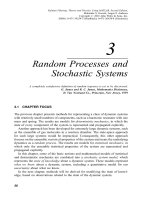
Chapter
3
presents various techniques
for
addressing these problems.
Network
ob-
servability
is
analyzed
in
Chapter
4,
where
a
brief
review
of
networks
and
Copyright 2004 by Marcel Dekker, Inc. All Rights Reserved.
graphs
is
foHowed
by the
description
of
alternative
methods
for
network
observability
determination.
Chapter
5 is
concerned with detecting
and
identifying
incorrect
measurements.
In
this
chapter,
it is
assumed
that
the
WLS
method
is
used
for
state estimation
and bad
data processing takes
place
after
the
convergence
of the WLS
state estimator.
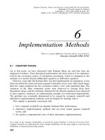
In
Chapter
6, the
topic
of
robust estimation
is
introduced
and
some
robust estimation
meth-
ods
which
have already
been
investigated
for
power
system
applications
are
presented.
Chapter
7 is
about
different
methods
of
estimating trans-
mission
line
parameters
and
transformer taps.
These
network
parameters
are
typically
assumed
to be
perfectly
known,
despite
the
fact
that errors
in
them
significantly
affect
the
state estimates.
The
problem
of
topology
error
identification
is the
topic
of
Chapter
8.
Topology
errors cause state
estimators
to
diverge
or
converge
to
incorrect
solutions.
The
challenges
in
detecting
and
identifying such errors
and
methods
of
overcoming
them
are
presented
in
this
chapter. Finally,
Chapter
9
discusses
the use of
ampere
measurements
and
various issues associated with
their
presence
in the
mea-
surement
set.
The
book
also
has two
appendices,
one on
basic
statistics
and the
other
on
sparse
linear
equations.
All
chapters, except
for the
first
one,
end
with
some
practice problems.
These
may be
useful
if
the
book
is
adopted
for
teaching
a
course
at
either
the
graduate
or
undergraduate
level.
The
first
five
chapters
are
recommended
to
be
read
in the
given order since each
one
builds
on the
previously covered
material.
However,
the
last
four chapters
can be
covered
in any
arbitrary
order.
Parts
of the
work
presented
in
this
book
have
been
funded
by the
United States National Science
Foundation
projects
ECS-9500118
and
ECS-
8909752
and by the
Spanish
Government,
Directory
of
Scientific
and
Tech-
nical
Investigations
(DGICYT)
Summer
Research
Grants
No. SAB
95-0354
and
SAB
92-0306,
and
Research
Project
No.
PB94-1430.
It
has
been
a
pleasure
to
work
with
our
many
graduate students
who
have contributed
to the
development
and
implementation
of
some
of the
ideas
in
this
book.
Specifically,
we are
happy
to
acknowledge
the
contri-
butions
made
by
Esther
Romero,
Francisco
Gonzalez,
Antonio
de
la
Villa,
Mehmet
Kemal
Celik,
Hongrae
Kim,
Fernando
Hugo
Magnago
and
Bei
Gou
in
their
respective research projects.
Finally,
we are
also grateful
for the
constant
encouragement
and
sup-
port
that
we
have received
from
our
spouses,
Aysen
and
Cati,
during
the
preparation
of
this
book.
Ali
Abur
Antonio
Gomez
Exposito
Copyright 2004 by Marcel Dekker, Inc. All Rights Reserved.
Contents
Foreword
(Fernando
L.
Alvarado)
Preface
1
Introduction
1.1
Operating
States
of
a
Power
System
1.2
Power
System
Security
Analysis
1.3
State
Estimation
1.4
Summary
2
Weighted
Least
Squares
State
Estimation
2.1
Introductio
2.2
Component
Modeling
and
Assumptions
2.2.1
Transmission Lines
2.2.2 Shunt Capacitors
or
Reactors
2.2.3
Tap
Changing
and
Phase
Shifting
Transformers
2.2.4
Loads
and
Generators
2.3
Building
the
Network
Model
2.4
Maximum
Likelihood Estimation
2.4.1
Gaussian
(Normal)
Probability
Density Function
2.4.2
The
Likelihood
Function
2.5
Measurement
Model
and
Assumptions
2.6
WLS
State
Estimation Algorithm
2.6.1
The
Measurement
Function,
A(a^)
2.6.2
The
Measurement
Jacobian,
R
2.6.3
The
Gain Matrix,
G
2.6.4
Cholesky
Decomposition
of (7
2.6.5 Performing
the
Forward/Back
Substitutions
2.7
Decoupled Formulation
of the
WLS
State
Estimation
2.8
DC
State
Estimation Model
2.9
Problems
Copyright 2004 by Marcel Dekker, Inc. All Rights Reserved.
3
Alternative
Formulations
of the
WLS
State
Estimation
3.1
Weaknesses
of
the
Normal Equations
Formulation
3.2
Orthogonal Factorization
3.3
Hybrid
Method
3.4
Method
of
Peters
and
Wilkinson
3.5
Equality-Constrained
WLS
State
Estimation
3.6
Augmented
Matrix Approach
3.7
Blocked
Formulation
3.8
Comparison
of
Techniques
3.9
Problems
References
4
Network
Observability
Analysis
4.1
Networks
and
Graphs
4.1.1
Graphs
4.1.2
Networks
4.2
NetworkMatrices
4.2.1
Branch
to Bus
Incidence Matrix
4.2.2 Fundamental
Loop
to
Branch
Incidence
Matrix
4.3
LoopEquations
4.4
Methods
of
Observability
Analysis
4.5
Numerical
Method
Based
on the
Branch
Variable
Formula-
tion
4.5.1
New
Branch
Variables
4.5.2
Measurement
Equations
4.5.3 Linearized Measurement Model
4.5.4
Observability
Analysis
4.6
Numerical
Method
Based
on the
Nodal
Variable
Formulation
4.6.1 Determining
the
Unobservable
Branches
4.6.2
Identification
of
Observable
Islands
4.6.3
Measurement
Placement
to
Restore
Observability
4.7
Topological
Observability
Analysis
Method
4.7.1
Topological
Observability
Algorithm
4.7.2
Identifying
the
Observable
Islands
4.8
Determination
of
Critical
Measurements
4.9
Measurement
Design
4.10
Summary
4.11
Problems
References
Copyright 2004 by Marcel Dekker, Inc. All Rights Reserved.
5 Bad
Data
Detection
and
Identification
5.1
Properties
of
Measurement
Residuals
5.2
Classification
of
Measurements
5.3
Bad
Data
Detection
and
IdentiRability
5.4
Bad
Data
Detection
5.4.1
Chi-squares
x^
Distribution
5.4.2
Use of
x^
Distribution
for Bad
Data
Detection
5.4.3
x^-Test
for
Detecting
Bad
Data
in
WLS
State
Esti-
mation
5.4.4
Use of
Normalized Residuals
for Bad
Data
Detection
5.5
Properties
of
Normalized Residuals
5.6
Bad
Data
Identification
5.7
Largest Normalized
Residual
(r^aa)
Test
5.7.1
Computational Issues
5.7.2 Strengths
and
Limitations
of
the
r^ag
Test
5.8
Hypothesis Testing
Identification
(HTI)
5.8.1
Statistical
Properties
of
eg
5.8.2 Hypothesis Testing
5.8.3 Decision Rules
5.8.4
HTI
Strategy
Under
Fixed
/3
5.9
Summary
5.10 Problems
Reference
6
Robust
State
Estimation
6.1
Introductio
6.2
Robustness
and
Breakdown
Points
6.3
Outliers
and
Leverage Points
6.3.1 Concept
of
Leverage Points
6.3.2
Identification
of
Leverage
Measurements
6.4
M-Estimators
6.4.1 Estimation
by
Newton's
Method
6.4.2
Iteratively
Re-weighted Least Squares
Estimation
6.5
Least
Absolute
Value
(LAV) Estimation
6.5.1 Linear Regression
6.5.2
LAV
Estimation
as an
LP
Problem
6.5.3 Simplex
Based
Algorithm
6.5.4
Interior
Point
Algorithm
6.6
Discussion
6.7
Problems
References
Copyright 2004 by Marcel Dekker, Inc. All Rights Reserved.
7
Network
Parameter
Estimation
7.1
Introduction
7.2
Influence
of
Parameter
Errors
on
State
Estimation
Results
7.3
Identification
of
Suspicious
Parameters
7.4
Classification
of
Parameter Estimation
Methods
7.5
Parameter Estimation Based
on
Residua!
Sensitivity
Analysis
7.6
Parameter Estimation Based
on
State
Vector
Augmentation
7.6.1
Solution
Using Conventional Normal Equation
7.6.2
Solution
Based
on
Kalman
Filter
Theory
7.7
Parameter Estimation Based
on
Historical
Series
of
Data
7.8
Transformer
Tap
Estimation
7.9
Observability
of
Network Parameters
7.10
Discussion
7.11
Problems
References
8
Topology
Error
Processing
8.1
Introduction
8.2
Types
of
Topology
Errors
8.3
Detection
of
Topology Errors
8.4
Classification
of
Methods
for
Topology Error
Analysis
8.5
Preliminary
Topology
Validation
8.6
Branch
Status
Errors
8.6.1
Residual
Analysis
8.6.2
State
Vector
Augmentation
8.7
Substation
Configuration
Errors
8.7.1
Inclusion
of
Circuit
Breakers
in the
Network Model
8.7.2
WLAV
Estimator
8.7.3
WLS
Estimator
8.8
Substation
Graph
and
Reduced Model
8.9
Implicit
Substation
Model:
State
and
Status
Estimation
8.10
Observability
Analysis
Revisited
8.11
Problems
References
9
State
Estimation
Using
Ampere
Measurements
9.1
Introduction
9.2
Modeling
of
Ampere
Measurements
9.3
Difficulties
in
Using
Ampere
Measurements
Copyright 2004 by Marcel Dekker, Inc. All Rights Reserved.
9.4
Inequality-Constrained State Estimation
9.5
Heuristic
Determination
of
F-#
Solution Uniqueness
9.6
Algorithmic Determination
of
Solution
Uniqueness
9.6.1 Procedure Based
on the
Residual
Covariance
Matrix
9.6.2 Procedure
Based
on the
Jacobian
Matrix
9.7
Identification
of
Nonuniquely
Observable Branches
9.8
Measurement
Classification
and Bad
Data
Identific
9.8.1
LS
Estimation
9.8.2
LAV
Estimation
9.9
Problems
References
Appendix
A
Review
of
Basic
Statistics
A.I
Random
Variables
A.2 The
Distribution
Function
(d.f.),
F(x)
A.3 The
Probability
Density Function
(p.d.f),
f(x)
A.4
Continuous Joint Distributions
A.5
Independent
Random
Variables
A.6
Conditional
Distributions
A.7
Expected
Value
A.8
Variance
A.9
Median
A.10
Mean
Squared Error
A.11
Mean
Absolute Error
A.12
Covariance
A.13
Normal
Distribution
A.14
Standard
Normal
Distribution
A.15
Properties
of
Normally
Distributed
Random
Variables
A.16
Distribution
of
Sample
Mean
A.17
Likelihood
Function
and
Maximum
Likelihood
Estimator
A.17.1
Properties
of
MLE's
A.18
Central
Limit
Theorem
for the
Sample
Mean
Appendix
B
Review
of
Sparse
Linear
Equation
Solution
B.I
Solution
by
Direct
Methods
B.2
Elementary
Matrices
B.3
LU
Factorization Using Elementary Matrices
B.3.1
Grout's
Algorithm
B.3.2
Dooh'ttle's
Algorithm
B.3.3
Factorization
of
Sparse Symmetric Matrice
B.3.4
Ordering Sparse Symmetric Matrices
B.4
Factorization Path
Graph
Copyright 2004 by Marcel Dekker, Inc. All Rights Reserved.
B.5
Sparse
Forward/Back
Substitutions
B.6
Solution
of
Modified Equations
B.6.1
Partial
Refactorization
B.6.2
Compensation
B.7
Sparse Inverse
B.8
Orthogonal
Factorization
B.9
Storage
and
Retrieval
of
Sparse Matrix Elements
B.10
Inserting
and/or
Deleting Elements
in a
Linked
List
B.10.1
Adding
a
Nonzero
Element
B.10.2
Deleting
a
Nonzero
Element
References
Copyright 2004 by Marcel Dekker, Inc. All Rights Reserved.
Chapter
1
Introduction
Power
systems
are
composed
of
transmission, sub-transmission,
distribution
and
generation
systems.
Transmission
systems
may
contain
large
numbers
of
substations
which
are
interconnected
by
transmission
lines,
transformers,
and
other devices
for
system
control
and
protection.
Power
may be
injected
into
the
system
by the
generators
or
absorbed
from
the
system
by the
loads
at
these substations.
The
output
voltages
of
generators
typically
do not
exceed
30-kV.
Hence,
transformers
are
used
to
increase
the
voltage
levels
to
levels
ranging
from
69-kV
all the way up to
765-kV
at the
generator
terminals
for
efficient
power
transmission.
High
voltage
is
preferred
at
the
transmission
system
for
different
reasons
one of
which
is to
minimize
the
copper
losses
that
are
proportional
to the
ampere
Rows
along
lines.
At the
receiving end,
the
transmission
systems
are
connected
to the
sub-
transmission
or
distribution
systems
which
are
operated
at
lower voltage
levels
ranging
from
115-KV
to
4.16-KV.
Distribution systems
are
typically
configured
to
operate
in
a
radial
configuration,
where
feeders stretch
from
distribution
substations
and
form
a
tree
structure with
their
roots
at the
substation
and
branches spreading over
the
distribution
area.
1.1
Operating
States
of a
Power
System
The
operating conditions
of a
power
system
at a
given point
in
time
can be
determined
if
the
network
model
and
complex
phasor
voltages
at
every sys-
tem bus are
known.
Since
the set of
complex
phasor voltages
fully
specifies
the
system,
it is
referred
to as the
static
state
of the
system.
According
to
[1],
the
system
may
move
into
one of
three possible states,
namely
normal,
emergency
and
restorative,
as the
operating conditions change.
A
power
system
is
said
to
operate
in a
normal
state
if
all
the
loads
in the
system
can be
supplied
power
by the
existing
generators without
violating
Copyright 2004 by Marcel Dekker, Inc. All Rights Reserved.
any
operational
constraints. Operational constraints include
the
limits
on
the
transmission
line
flows,
as
well
as the
upper
and
lower
limits
on bus
voltage
magnitudes.
A
normal
state
is
said
to be
secwre
if
the
system
can
remain
in a
normal
state following
the
occurrence
of
each contingency
from
a
list
of
critical
contingencies.
Common
contingencies
of
interest
are
trans-
mission
line
or
generator
outages
due to
unexpected
failures
of
equipment
or
natural
causes such
as
storms.
Otherwise,
the
normal
state
is
classified
as
msecwe
where
the
power
balance
at
each
bus and
all
operating inequality
constraints
are
still
satisfied,
yet the
system
remains
vulnerable with
re-
spect
to
some
of the
considered contingencies.
If the
system
is
found
to be
in
a
normal
but
msecwe
operating state then, preventive
actions
must
be
taken
to
avoid
its
move
into
an
emergency
state.
Such
preventive controls
can be
determined typically
by the
help
of a
security constrained optimal
power
flow
program
which
accounts
for a
list
of
critical
contingencies.
Operating conditions
may
change
significantly
due to an
unexpected
event
which
may
cause
the
violation
of
some
of the
operating constraints,
while
the
power
system
continues
to
supply
power
to all the
loads
in the
system.
In
such
a
situation
the
system
is
said
to be
operating
in an
emer-
gency
state.
Emergency
state requires
immediate
corrective action
to be
taken
by the
operator
so as to
bring
the
system
back
to a
normal
state.
While
the
system
is in the
emergency
state, corrective control
measures
may be
able
to
avoid
system
collapse
at the
expense
of
disconnecting various
loads,
lines,
transformers
or
other
equipment.
As a
result,
the
operating
limit
violations
may be
eliminated
and the
system
may
recover
stability
with reduced load
and
reconfigured topology.
Then,
the
load
versus gener-
ation
balance
may
have
to be
restored
in
order
to
start
supplying
power
to
all
the
loads.
Such
an
operating state
is
called
the
restorative
state,
and the
actions
to be
taken
in
order
to
transform
it
into
a
normal
state
are
referred
to
as
restorative
controls.
The
state
diagram
in
Figure
1.1
illustrates
the
possible
transitions
between
the
different
operating states defined above.
1.2
Power
System
Security
Analysis
Power
systems
are
operated
by
system
operators
from
the
area control
centers.
The
main
goal
of the
system
operator
is to
maintain
the
system
in
the
normal
secure state
as the
operating conditions vary during
the
daily
operation.
Accomplishing
this
goal requires continuous monitoring
of the
system
conditions, identification
of the
operating state
and
determination
of
the
necessary preventive actions
in
case
the
system
state
is
found
to be
msecwe.
This
sequence
of
actions
is
referred
to as the
security analysis
of
the
system.
The
first
stop
of
security analysis
is to
monitor
the
current
state
of
the
system. This involves acquisition
of
measurements
from
all
parts
of the
Copyright 2004 by Marcel Dekker, Inc. All Rights Reserved.
NORMAL
STATE
SECURE
or
INSECURE
RESTORATIVE
STATE
PARTIAL
OR
TOTAL
BLACKOUT
EMERGENCY
STATE
OPERATIONAL
LIMITS
ARE
VIOLATED
Figure
1.1.
State
Diagram
for
Power
System Operation
system
and
then processing
them
in
order
to
determine
the
system
state.
The
measurements
may be
both
of
analog
and
digital
(on/off status
of
devices) type. Substations
are
equipped with devices
called
remote
terminal
units
(RTU)
which
collect
various types
of
measurements
from
the
field
and are
responsible
for
transmitting
them
to the
control center.
More
recently,
the
so-called
intelligent
electronic
devices
(IED)
are
replacing
or
complementing
the
existing
RTUs.
It is
possible
to
have
a
mixture
of
these
devices
connected
to a
local
area
network
(LAN)
along
with
a
SCADA
front
end
computer,
which
supports
the
communication
of the
collected
measurements
to the
host
computer
at the
control center.
The
SCADA
host
computer
at the
control center
receives
measurements
from
all
the
monitored substations'
SCADA
systems
via one of
many
possible types
of
communication
links
such
as
fiber
optics,
satellite,
microwave,
etc.
Figure
1.2
shows
the
configuration
of the
EMS/SCADA
system
for a
typical
power
system.
Measurements
received
at the
control center
will
include
line
power
Hows,
bus
voltage
and
line
current magnitudes, generator outputs,
loads,
circuit
breaker
and
switch status information, transformer
tap
positions,
and
switchable
capacitor
bank
values.
These
raw
data
and
measurements
are
processed
by the
state
estimator
in
order
to
filter
the
measurement
noise
and
detect gross
errors.
State estimator solution
will
provide
an
optimal
estimate
of the
system
state
based
on the
available
measurements
and on
the
assumed
system
model.
This
will
then
be
passed
on to all the
energy
management
system
(EMS)
application
functions such
as
the
contingency
analysis,
automatic generation
control,
load
forecasting
and
optimal
power
now,
etc.
The
same
information
will
also
be
available
via a LAN
connection
Copyright 2004 by Marcel Dekker, Inc. All Rights Reserved.
PLANNING
ANALYSIS
FUNCTIONS
LocaiArea
Network
ENERGY
MANAGEMENT
FUNCTtONS
A
]
t
Communications
^Network
Contro]
Center
SCADAFrontEnd
RTU
RTU
!ED
1
!ED
RTU
Loca!Area
Network
Monitored
Devices
Substation
Figure
1.2.
EMS/SCAOA
system
configuration.
to
the
corporate
offices
where
other planning
and
analysis functions
can be
executed
off-line.
Initially,
power
systems
were
monitored
only
by
supervisory control sys-
tems.
These
are
control
systems
which
essentially monitor
and
control
the
status
of
circuit
breakers
at the
substations. Generator outputs
and the
sys-
tem
frequency
were
also
monitored
for
purposes
of
Automatic
Generation
Control
(AGC)
and
Economic
Dispatch
(ED).
These
supervisory
control
systems
were
later
augmented
by
real-time system-wide data acquisition
capabilities,
allowing
the
control centers
to
gather
all
sorts
of
analog mea-
surements
and
circuit
breaker status data
from
the
power
system.
This
led
to
the
establishment
of the
first
Supervisory
Control
and
Data
Acquisition
(SCADA)
Systems.
The
main
motivation behind
this
development
was the
facilitation
of
security analysis. Various application functions
such
as
con-
tingency
analysis, corrective
real
and
reactive
power
dispatch could
not be
executed without
knowing
the
real-time operating conditions
of the
system.
However,
the
information provided
by the
SCADA
system
may not
always
be
reliable
due to the
errors
in the
measurements,
telemetry
failures,
com-
munication noise, etc.
Furthermore,
the
collected
set of
measurements
may
not
allow
direct
extraction
of the
corresponding
A.C.
operating state
of the
system.
For
instance,
bus
voltage
phase
angles
are not
typically
measured,
and not
all
the
transmission
line
flows
are
available.
Besides,
it may not be
economically
feasible
to
telemeter
all
possible
measurements
even
if
they
are
available
from
the
transducers
at the
substations.
Copyright 2004 by Marcel Dekker, Inc. All Rights Reserved.
1.3
State
Estimation
The
foregoing concerns
were
first
recognized
and
subsequently addressed
by
Fred
Schweppe,
who
proposed
the
idea
of
state
estimation
in
power
sys-
tems
[2, 3,
4].
Introduction
of the
state estimation function broadened
the
capabilities
of the
SCADA
system
computers,
leading
to the
establishment
of
the
Energy
Management
Systems
(EMS),
which
would
now be
equipped
with,
among
other application functions,
an
on-line State Estimator
(SE).
In
order
to
identify
the
current operating state
of the
system,
state
estimators
facilitate
accurate
and
efficient
monitoring
of
operational con-
straints
on
quantities such
as the
transmission
line
loadings
or bus
voltage
magnitudes.
They
provide
a
reliable
real-time
data base
of the
system,
including
the
existing state
based
on
which, security
assessment
functions
can be
reliably
deployed
in
order
to
analyze contingencies,
and to
determine
any
required corrective actions.
The
state estimators
typically
include
the
following
functions:
*
Topology
processor:
Gathers
status data about
the
circuit
breakers
and
switches,
and
configures
the
one-line
diagram
of the
system.
*
Observability analysis:
Determines
if a
state estimation solution
for
the
entire
system
can be
obtained using
the
available
set of
mea-
surements.
Identifies
the
unobservable
branches,
and the
observable
islands
in the
system
if any
exist.
<
State estimation solution:
Determines
the
optimal estimate
for the
system
state,
which
is
composed
of
complex
bus
voltages
in the en-
tire
power
system,
based
on the
network
model
and the
gathered
measurements
from
the
system.
Also provides
the
best estimates
for
all
the
line
Hows,
loads, transformer taps,
and
generator outputs.
* Bad
data processing: Detects
the
existence
of
gross errors
in
the
mea-
surement
set.
Identifies
and
eliminates
bad
measurements
provided
that
there
is
enough
redundancy
in the
measurement
configuration.
<
Parameter
and
structural
error processing: Estimates various net-
work
parameters, such
as
transmission
line
model
parameters,
tap
changing transformer
parameters,
shunt capacitor
or
reactor
param-
eters.
Detects structural errors
in the
network
configuration
and
identifies
the
erroneous breaker status provided that there
is
enough
measurement
redundancy.
Thus,
power
system
state
estimator constitutes
the
core
of the
on-line
security
analysis function.
It
acts
like
a
filter
between
the raw
measurements
received
from
the
system
and
all
the
application functions that
require
the
most
reliable
data base
for the
current
state
of the
system.
Figure
1.3
Copyright 2004 by Marcel Dekker, Inc. All Rights Reserved.
describes
the
data
and
functional
interfaces
between
the
various applica-
tion
functions involved
in the
on-line
static
security
assessment
procedure.
Raw
measurements
which
include
the
switch
and
circuit
breaker positions
in
the
substations,
are
processed
by the
topology processor,
which
in
turn
generates
a
bus/branch
model
of the
power
system.
This
model
not
only
in-
cludes
all
buses within
the
area
of the
control center EMS,
but
also selected
buses
from
the
neighboring
systems.
The
information
and
measurements
obtained
from
the
neighboring
systems
are
used
to
build
and
update
the
external
system
model.
Furthermore,
there
may be
unobservable
pockets
within one's
own
area
due to
temporary
loss
of
telemetry,
rejected
bad
data
or
other
unexpected
failures.
Such
areas
whether
physically located
within
the
control area
or
part
of the
external
system,
will
be
estimated
via
the
use of
pseudo
measurements.
Pseudo
measurements
can be
generated
based
on
short
term
load forecasts, generation dispatch,
historical
records
or
other similar
approximation
methods.
Naturally, they
are
assigned high
variances
(low
weights)
or
they
can be
forced
to be
critical
measurements
by
design. Definition
and
properties
of a
critical
measurement
will
be
dis-
cussed
in
detail
in
chapter
5. In
addition, there
may be
passive buses with
no
generation
or
load,
having
net
zero
real
and
reactive
power
injection.
Such
bus
injections,
even
though
not
measured,
can be
used
as
error
free
measurements
in the
state estimation formulation
and
referred
to as
"vir-
tual"
measurements.
The
results obtained
by the
state estimator
will
be
checked
in
order
to
classify
the
system
state into
one of the
three categories
shown
in
Figure 1.1.
If it is
found
to be in the
normal
state, then contin-
gency
analysis
will
be
carried
out to
determine
the
system
security against
a
set
of
predetermined contingencies.
In
case
of
insecurity,
preventive control
actions have
to be
calculated
via the use of a
software
tool
such
as a
security
constrained
optimal
power
flow.
Implementing
these preventive
measures
will
move
the
system
into
the
desired
normal
and
secwe
state. Figure
1.3
also
indicates
the
emergency
and
restorative control actions
which
will
be
deployed
under
a&nonnaZ
operating conditions,
however
these topics
are
beyond
the
scope
of
this
book
and
will
not be
discussed
any
further.
1.4
Summary
Power
systems
are
continuously
monitored
in
order
to
maintain
the
oper-
ating
conditions
in a
normal
and
secure state. State estimation function
is
used
for
this
purpose.
It
processes
redundant
measurements
in
order
to
pro-
vide
an
optimal estimate
of the
current operating state. State estimation
problem
has
been
investigated
by
several researchers since
its
introduc-
tion
in the
late
1960s.
Being
an
on-line function,
computational
issues
re-
lated
to
speed, storage
and
numerical
robustness
of the
solution algorithms
have been
carefully
studied.
Measurement
configuration
and
its
effect
on
Copyright 2004 by Marcel Dekker, Inc. All Rights Reserved.
Figure
1.3.
On-line
Static
Security
Assessment:
Functional
Diagram
state
estimation have been addressed
by the
developed
observability
anal-
ysis
methods. State estimators
also
function
as
filters
against
incorrect
measurements,
data
and
other information
received
through
the
SCADA
system.
Hence,
the
subject
of bad
data processing
has
been investigated
and
detection/identification
algorithms
for
errors
in
analog
measurements
have been developed. Special
methods
also
exist
for the
identification
of
those
errors
related
to the
topology information and/or
network
parame-
ters.
On the
other
hand,
the use of
ampere
measurements
present
some
problems
which
do not
exist
in
their
absence from
the
measurement
set.
In the
following
chapters, these issues
will
be
presented
in
more
detail
and
methods
which
are
developed
to
address
them
will
be
described.
References
[1]
Dy
Liacco
T.E.,
"Real-Time
Computer
Control
of
Power
Systems",
Proceedings
of the
IEEE,
Vol.
62,
No.7,
July 1974,
pp.884-891.
[2]
Schweppe
F.C.
and
Wildes
J.,
"Power
System
Static-State
Estimation,
Part
I:
Exact
Model",
IEEE
Transactions
on
Power
Apparatus
and
Systems,
Vol.PAS-89,
January
1970,
pp.
120-125.
Copyright 2004 by Marcel Dekker, Inc. All Rights Reserved.
[3]
Schweppe
F.C.
and Rom
D.B.,
"Power
System
Static-State
Estima-
tion,
Part
II:
Approximate
Model",
IEEE
Transactions
on
Power
Ap-
paratus
and
Systems,
Vol.PAS-89,
January 1970,
pp.125-130.
[4]
Schweppe
F.C.,
"Power
System
Static-State
Estimation,
Part III:
Im-
plementation"
,
IEEE
Transactions
on
Power
Apparatus
and
Systems,
Vol.PAS-89,
January
1970,
pp.
130-135.
[5]
Fink
L.H.
and
Carlsen
K.,
"Operating under
Stress
and
Strain",
IEEE
Spectrum,
March
1978.
[6]
N.
Balu
et
al.
"On-line
Power
System
Security
Analysis",
Proc.
of the
IEEE,
vol.
80(2),
pp.
262-280.
Copyright 2004 by Marcel Dekker, Inc. All Rights Reserved.
Chapter
2
Weighted
Least
Squares
State
Estimation
2.1
Introduction
Static
state
estimation
refers
to the
procedure
of
obtaining
the
voltage
phasors
at all of the
system
buses
at a
given point
in
time.
This
can be
achieved
by
direct
means
which
involve very accurate synchronized
phasor
measurements
of
all
bus
voltages
in the
system.
However,
such
an
approach
would
be
very vulnerable
to
measurement
errors
or
telemetery
failures.
In-
stead,
state estimation procedure
makes
use of a set of
redundant
mea-
surements
in
order
to
filter
out
such
errors
and
find
an
optimal estimate.
The
measurements
may
include
not
only
the
conventional
power
and
volt-
age
measurements,
but
also those others such
as the
current
magnitude
or
synchronized voltage phasor
measurements
as
well.
Simultaneous
measure-
ment
of
quantities
at
different
parts
of the
system
is
practically
impossible,
hence
a
certain
amount
of
time
skew
between
measurements
is
commonly
tolerated.
This
tolerance
is
justified
due to the
slowly varying operating
conditions
of the
power
systems
under
normal
operating conditions.
The
definition
of the
system
state usually includes
the
steady state
bus
voltage
phasors
only.
This
implies that
the
network
topology
and
param-
eters
are
perfectly
known.
However,
errors
in the
network
parameters
or
topology
do
exist
occasionally,
due to
various reasons such
as
unreported
outages, transmission
line
sags
on hot
days, etc. Detection
and
correction
of
such errors
will
be
separately discussed
later
on in
chapters
7 and 8.
Copyright 2004 by Marcel Dekker, Inc. All Rights Reserved.
2.2
Component
Modeling
and
Assumptions
Power
system
is
assumed
to
operate
in the
steady
state
under balanced
conditions.
This
implies
that
all bus
loads
and
branch
power
flows
will
be
three
phase
and
balanced,
all
transmission
lines
are
fully
transposed,
and
all
other
series
or
shunt devices
are
symmetrical
in the
three
phases.
These
assumptions allow
the use of
single
phase
positive
sequence
equivalent
circuit
for
modeling
the
entire
power
system.
The
solution
that
will
be
obtained
by
using such
a
network
model,
will
also
be the
positive
sequence
component
of the
system
state
during balanced steady
state
operation.
As
in
the
case
of the
power
flow,
all
network data
as
well
as the
network
variables,
are
expressed
in the per
unit
system.
The
following
component
models
will
thus
be
used
in
representing
the
entire
network.
2.2.1
Transmission
Lines
Transmission
lines
are
represented
by a
two-port
7r-model
whose
parameters
correspond
to the
positive
sequence equivalent
circuit
of
transmission
lines.
A
transmission
line
with
a
positive
sequence
series
impedance
of
.R+j^f
and
total
line
charging
susceptance
of
j23,
will
be
modelled
by the
equivalent
circuit
shown
in
Figure
2.1.
Figure
2.1.
Equivaient
circuit
for a
transmission
tine
2.2.2
Shunt
Capacitors
or
Reactors
Shunt capacitors
or
reactors
which
may be
used
for
voltage and/or
reactive
power
control,
are
represented
by
their
per
phase susceptance
at the
corre-
sponding bus.
The
sign
of the
susceptance
value
will
determine
the
type
of
the
shunt element.
It
will
be
positive
or
negative corresponding
to a
shunt
capacitor
or
reactor
respectively.
2.2.3
Tap
Changing
and
Phase
Shifting
Transformers
Transformers with off-nominal
but
in-phasc
taps,
can be
modeled
as
series
impedances
in
scries
with
ideal
transformers
as
shown
in
Figure 2.2.
The
Copyright 2004 by Marcel Dekker, Inc. All Rights Reserved.