TCP/IP Tutorial and Technical Overview phần 6 pps
Bạn đang xem bản rút gọn của tài liệu. Xem và tải ngay bản đầy đủ của tài liệu tại đây (547.52 KB, 100 trang )
476 TCP/IP Tutorial and Technical Overview
LDAP interface for the GDA
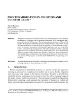
One way LDAP is being integrated into DCE is to allow DCE cells to be
registered in LDAP directories. The GDA in a cell that wants to connect to remote
cells is configured to enable access to the LDAP directory (see Figure 12-17).
Figure 12-17 The LDAP interface for GDA
DCE originally only supported X.500 and DNS name syntax for cell names.
LDAP and X.500 names both follow the same hierarchical naming model, but
their syntax is slightly different. X.500 names are written in reverse order and use
a slash (/) rather than a comma (,) to separated relative distinguished names.
When the GDA is configured to use LDAP, it converts cell names in X.500 format
into the LDAP format.
LDAP interface for the CDS
DCE provides two programming interfaces to the Directory Service; Name
Service Interface (NSI) and the X/Open Directory Service (XDS). XDS is an
X.500-compatible interface used to access information in the GDS, and it can
also be used to access information in the CDS. However, the use of NSI is much
more common in DCE applications. The NSI API provides functionality that is
specifically tailored for use with DCE client and server programs that use RPC.
NSI allows servers to register their address and the type of RPC interface they
support. This address/interface information is called an RPC binding, and is
Chapter 12. Directory and naming protocols 477
needed by clients that want to contact the server. NSI allows clients to search the
CDS for RPC binding information.
NSI was designed to be independent of the directory where the RPC bindings
are stored. However, the only supported directory to date has been CDS. NSI will
be extended to also support adding and retrieving RPC bindings from an LDAP
directory. This will allow servers to advertise their RPC binding information in
either CDS or an LDAP directory. Application programs can use either the NSI or
the LDAP API when an LDAP directory is used (see Figure 12-18).
Figure 12-18 The LDAP interface for NSI
12.4.8 The Directory-Enabled Networks (DEN) initiative
In September 1997, Cisco Systems Inc. and Microsoft® Corp. announced the
so-called Directory-Enabled Networks (DEN) initiative as a result of a
collaborative work. Many companies, such as IBM, either support this initiative or
actively participate in ad hoc working groups (ADWGs). DEN represents an
information model specification for an integrated directory that stores information
about people, network devices, and applications. The DEN schema defines the
object classes and their related attributes for those objects. As such, DEN is a
478 TCP/IP Tutorial and Technical Overview
key piece to building intelligent networks, where products from multiple vendors
can store and retrieve topology and configuration-related data.
Of special interest is that the DEN specification defines LDAPv3 as the core
protocol for accessing DEN information, which makes information available to
LDAP-enabled clients or network devices, or both.
DEN makes use of the Common information Model (CIM). CIM details a way of
integrating different management models such as SNMP MIBs and DMTF MIFs.
At the time of writing, the most current CIM schema was version 2.12, released in
April of 2006.
More information about the DEN initiative can be found on the founder’s Web at:
/> />12.4.9 Web-Based Enterprise Management (WBEM)
WBEM is a set of standards designed to deliver an integrated set of
management tools for the enterprise. By making use of XML and CIM, it
becomes possible to manage network devices, desktop systems, telecom
systems and application systems, all from a Web browser. For further
information, see:
/>12.5 RFCs relevant to this chapter
The following RFCs provide detailed information about the directory and naming
protocols and architectures presented throughout this chapter:
RFC 1032 – Domain administrators guide (November 1987)
RFC 1033 – Domain administrators operations guide (November 1987)
RFC 1034 – Domain names - concepts and facilities (November 1987)
RFC 1035 – Domain names - implementation and specifications
(November 1987)
RFC 1101 – DNS encoding of network names and other types (April 1989)
RFC 1183 – New DNS RR Definitions (October 1990)
RFC 1202 – Directory Assistance service (February 1991)
RFC 1249 – DIXIE Protocol Specification (August 1991)
RFC 1348 – DNS NSAP RRs (July 1992)
Chapter 12. Directory and naming protocols 479
RFC 1480 – The US Domain (June 1993)
RFC 1706 – DNS NSAP Resource Records (October 1994)
RFC 1823 – The LDAP Application Programming Interface (August 1995)
RFC 1876 – A Means for Expressing Location Information in the Domain
Name System (January 1996)
RFC 1995 – Incremental Zone Transfer in DNS (August 1996)
RFC 1996 – A Mechanism for Prompt Notification of Zone Changes (DNS
NOTIFY) (August 1996)
RFC 2136 – Dynamic Updates in the Domain Name System (DNS UPDATE)
(April 1997)
RFC 2444 – The One-time-Password SASL Mechanism (October 1998)
RFC 4592 – The Role of Wildcards in the Domain Name System (July 2006)
RFC 2743 – Generic Security Service Application Program Interface Version
2, Update 1 (January 2000)
RFC 2874 – DNS Extensions to Support IPv6 Address Aggregation and
Renumbering (July 2000)
RFC 3007 – Secure Domain Name Systems (DNS) Dynamic Update
(November 2000)
RFC 3494 – Lightweight Directory Access protocol version 2 (LDAPv2)
(March 2003)
RFC 3596 – DNS Extensions to Support IP Version 6 (October 2003)
RFC 3645 – Generic Security Service Algorithm for Secret Key Transaction
Authentication for DNS (GSS-TSIG) (October 2003)
RFC 3901 – DNS IPv6 Transport Operational Guidelines (September 2004)
RFC 4033 – DNS Security Introduction and Requirements (March 2005)
RFC 4034 – Resource Records for the DNS Security Extensions
(March 2005)
RFC 4035 – Protocol Modifications for the DNS Security Extensions
(March 2005)
RFC 4339 – IPv6 Host Configuration of DNS Server Information Approaches
(February 2006)
RFC 4398 – Storing Certificates in the Domain Name System (DNS)
(March 2006)
RFC 4422 – Simple Authentication and Security Layer (SASL) (June 2006)
RFC 4501 – Domain Name System Uniform Resource Identifiers (May 2006)
480 TCP/IP Tutorial and Technical Overview
RFC 4505 – Anonymous Simple Authentication and Security Layer (SASL)
(June 2006)
RFC 4510 – Lightweight Directory Access Protocol (LDAP): Technical
Specification Road Map (June 2006)
RFC 4511 – Lightweight Directory Access Protocol (LDAP): The Protocol
(June 2006)
RFC 4512 – Lightweight Directory Access Protocol (LDAP): Directory
Information Models (June 2006)
RFC 4513 – Lightweight Directory Access Protocol (LDAP): Authentication
Methods and Security Mechanisms (June 2006)
RFC 4514 – Lightweight Directory Access Protocol (LDAP): String
Representation of Distinguished Names (June 2006)
RFC 4515 – Lightweight Directory Access Protocol (LDAP): String
Representation of Search Filters (June 2006)
RFC 4516 – Lightweight Directory Access Protocol (LDAP): Uniform
Resource Locator (June 2006)
RFC 4517 – Lightweight Directory Access Protocol (LDAP): Syntaxes and
Matching Rules (June 2006)
RFC 4518 – Lightweight Directory Access Protocol (LDAP): Internationalized
String Preparation (June 2006)
RFC 4519 – Lightweight Directory Access Protocol (LDAP): Schema for User
Applications (June 2006)
RFC 4520 – Internet Assigned Numbers Authority (IANA) Considerations for
the Lightweight Directory Access Protocol (LDAP) (June 2006)
RFC 4521 – Considerations for Lightweight Directory Access Protocol
(LDAP) (June 2006)
RFC 4522 – Lightweight Directory Access Protocol (LDAP): The Binary
Encoding Option (June 2006)
RFC 4523 – Lightweight Directory Access Protocol (LDAP): Schema
Definitions for X.509 Certificates (June 2006)
RFC 4524 – Lightweight Directory Access Protocol (LDAP): COSINE/LDAP
X.500 Schema (June 2006)
RFC 4525 – Lightweight Directory Access Protocol (LDAP): Modify-Increment
Extension (June 2006)
RFC 4526 – Lightweight Directory Access Protocol (LDAP): Absolute True
and False Filters (June 2006)
Chapter 12. Directory and naming protocols 481
RFC 4527 – Lightweight Directory Access Protocol (LDAP): Read Entry
Controls (June 2006)
RFC 4528 – Lightweight Directory Access Protocol (LDAP): Assertion Control
(June 2006)
RFC 4529 – Requesting Attributes by Object Class in the Lightweight
Directory Access Protocol (LDAP) (June 2006)
RFC 4530 – Lightweight Directory Access Protocol (LDAP): entryUUID
Operational Attribute (June 2006)
RFC 4531 – Lightweight Directory Access Protocol (LDAP): Turn Operation
(June 2006)
RFC 4532 – Lightweight Directory Access Protocol (LDAP): “Who Am I?”
Operation (June 2006)
RFC 4533 – Lightweight Directory Access Protocol (LDAP): Content
Synchronization Operation (June 2006)
482 TCP/IP Tutorial and Technical Overview
© Copyright IBM Corp. 1989-2006. All rights reserved. 483
Chapter 13. Remote execution and
distributed computing
One of the most fundamental mechanisms employed on networked computers is
the ability to execute on the remote systems. That is, a user wants to invoke an
application on a remote machine. A number of application protocols exist to allow
this remote execution capability, most notably the Telnet protocol. This chapter
discusses some of these protocols. In addition, we discuss the concept of
distributed computing.
13
484 TCP/IP Tutorial and Technical Overview
13.1 Telnet
Telnet is a standard protocol with STD number 8. Its status is recommended. It is
described in RFC 854 – Telnet Protocol Specifications and RFC 855 – Telnet
Option Specifications.
The Telnet protocol provides a standardized interface, through which a program
on one host (the Telnet client) can access the resources of another host (the
Telnet server) as though the client were a local terminal connected to the server.
See Figure 13-1 for more details.
For example, a user on a workstation on a LAN can connect to a host attached to
the LAN as though the workstation were a terminal attached directly to the host.
Of course, Telnet can be used across WANs as well as LANs.
Figure 13-1 Telnet operation
Most Telnet implementations do not provide you with graphics capabilities.
13.1.1 Telnet operation
Telnet protocol is based on three ideas:
The Network Virtual Terminal (NVT) concept. An NVT is an imaginary device
with a basic structure common to a wide range of real terminals. Each host
maps its own terminal characteristics to those of an NVT and assumes that
every other host will do the same.
Workstation Terminal
Host
LAN
Remote
Login
Local
Login
Chapter 13. Remote execution and distributed computing 485
A symmetric view of terminals and processes.
Negotiation of terminal options. The principle of negotiated options is used by
the Telnet protocol, because many hosts want to provide additional services,
beyond those available with the NVT. Various options can be negotiated. The
server and client use a set of conventions to establish the operational
characteristics of their Telnet connection through the “DO, DONT, WILL,
WONT” mechanism discussed later in this chapter.
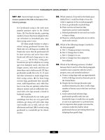
The two hosts begin by verifying their mutual understanding. After this initial
negotiation is complete, they are capable of working on the minimum level
implemented by the NVT. After this minimum understanding is achieved, they
can negotiate additional options to extend the capabilities of the NVT to reflect
more accurately the capabilities of the real hardware in use. Because of the
symmetric model used by Telnet (see Figure 13-2), both the host and the client
can propose additional options to be used.
Figure 13-2 Telnet negotiations
13.1.2 Network Virtual Terminal
The NVT has a printer (or display) and a keyboard. The keyboard produces
outgoing data, which is sent over the Telnet connection. The printer receives the
incoming data. The basic characteristics of an NVT, unless they are modified by
mutually agreed options, are:
The data representation is 7-bit ASCII transmitted in 8-bit bytes.
The NVT is a half-duplex device operating in a line-buffered mode.
Operating System
Operating System
TCP/IP TCP/IP
TelnetTelnet
Telnet
NVT
NVT
Host A Host B
Negotiations
486 TCP/IP Tutorial and Technical Overview
The NVT provides a local echo function.
All of these can be negotiated by the two hosts. For example, a local echo is
preferred because of the lower network load and superior performance, but there
is an option for using a remote echo (see Figure 13-3), although no host is
required to use it.
Figure 13-3 Telnet: Echo option
An NVT printer has an unspecified carriage width and page length. It can handle
printable ASCII characters (ASCII code 32 to 126) and understands some ASCII
control characters, such as those shown in Table 13-1.
Table 13-1 ASCII control characters
Command ASCII Action
NULL (NUL) 0 No operation.
Line feed (LF) 10 Moves printer to next line, keeping the
same horizontal position.
Carriage return (CR) 13 Moves the printer to the next left margin.
BELL (BEL) 7 Produces and audible or visible signal.
Backspace (BS) 8 Moves print head one character position
towards the left margin.
A
A
Z
Keyboard
Printer
Input
Output
Terminal (Client)
Host (Server)
Remote
Echo
Local
Echo
Chapter 13. Remote execution and distributed computing 487
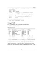
13.1.3 Telnet options
There is an extensive set of Telnet options, and the reader should consult
STD 1 – Official Internet Protocol Standards for the standardization state and
status for each of them. At the time of writing, the following options were defined
(Table 13-2).
Table 13-2 Telnet options
Horizontal tab (HT) 9 Moves print head to the next horizontal
tab stop.
Vertical tab (VT) 11 Moves printer to next vertical tab stop.
Form feed (FF) 12 Moves to top of next page, keeping the
same horizontal position.
Command ASCII Action
Number Name State RFC STD
0 Binary transmission Standard 856 27
1 Echo Standard 857 28
3 Suppress Go Ahead Standard 858 29
5 Status Standard 859 30
6 Timing mark Standard 860 31
255 Extended options list Standard 861 32
34 Linemode Draft 1184
2 Reconnection Proposed
4 Approximate, message size
negotiation
Proposed
7 Remote controlled trans and
echo
Proposed 726
8 Output line width Proposed
9 Output page size Proposed
10 Output carriage-return
disposition
Proposed 652
11 Output horizontal tab stops Proposed 653
488 TCP/IP Tutorial and Technical Overview
12 Output horizontal tab
disposition
Proposed 654
13 Output form feed disposition Proposed 655
14 Output vertical tab stops Proposed 656
15 Output vertical tab disposition Proposed 657
16 Output line feed disposition Proposed 658
17 Extended ASCII Proposed 698
18 Logout Proposed 727
19 Byte macro Proposed 735
20 Data entry terminal Proposed 1043
21 SUPDUP Proposed 736
22 SUPDUP output Proposed 749
23 Send location Proposed 779
24 Terminal type Proposed 1091
25 End of record Proposed 885
26 TACACS user identification Proposed 927
27 Output marking Proposed 933
28 Terminal location number Proposed 946
29 Telnet 3270 regime Proposed 1041
30 X.3 PAD Proposed 1053
31 Negotiate window size Proposed 1073
32 Terminal speed Proposed 1079
33 Remote flow control Proposed 1372
35 X Display location Proposed 1096
39 Telnet environment option Proposed 1572
40 TN3270 enhancements Proposed 1647
37 Telnet authentication option Experimental 1416
Number Name State RFC STD
Chapter 13. Remote execution and distributed computing 489
All of the standard options have a status of recommended and the remainder
have a status of elective. There is a historic version of the Telnet Environment
option which is not recommended; it is Telnet option 36 and was defined in RFC
1408.
Full-screen capability
Full-screen Telnet is possible provided the client and server have compatible
full-screen capabilities. For example, VM and MVS provide a TN3270-capable
server. To use this facility, a Telnet client must support TN3270.
13.1.4 Telnet command structure
The communication between client and server is handled with internal
commands, which are not accessible by users. All internal Telnet commands
consist of 2- or 3-byte sequences, depending on the command type.
41 Telnet xauth Experimental
42 Telnet charset Experimental 2066
43 Telnet remote serial port Experimental
44 Telnet com port control Experimental 2217
Number Name State RFC STD
490 TCP/IP Tutorial and Technical Overview
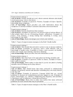
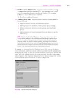
The Interpret As Command (IAC) character is followed by a command code. If
this command deals with option negotiation, the command will have a third byte
to show the code for the referenced option. See Figure 13-4 for more details.
Figure 13-4 Telnet: Internal Telnet command proposes negotiation about terminal type
Table 13-3 shows some of the possible command codes.
Table 13-3 Command codes
Command Code Comments
SE 240 End of sub-negotiation parameters.
NOP 241 No operation.
Data Mark 242 The data stream portion of a sync. This must
always be accompanied by a TCP urgent
notification.
Break 243 NVT character BRK.
Go Ahead 249 The GA signal.
SB 250 Start of sub-negotiation of option indicated by the
immediately following code.
Interpret
as
Command
Command
Code
Option
Negotiated
byte 1 byte 3
byte 2
Sample:
255 253
24
Terminal Type
WILL
IAC
Chapter 13. Remote execution and distributed computing 491
13.1.5 Option negotiation
Using internal commands, Telnet is able to negotiate options in each host. The
starting base of negotiation is the NVT capability: Each host to be connected
must agree to this minimum. Every option can be negotiated by the use of the
four command codes WILL, WONT, DO, and DONT. In addition, some options
have suboptions: If both parties agree to the option, they use the SB and SE
commands to manage the sub-negotiation. Table 13-4 shows a simplified
example of how option negotiation works.
Table 13-4 Option negotiation
WILL 251 Shows desire to use, or confirmation of using, the
option indicated by the code immediately
following.
WONT 252 Shows refusal to use or continue to use the option.
DO 253 Requests that other party uses, or confirms that
you are expecting the other party to use, the
option indicated by the code immediately
following.
DONT 254 Demands that the other party stop using, or
confirms that you are no longer expecting the
other party to use, the option indicated by the code
immediately following.
IAC 255 Interpret As command. Indicates that what follows
is a Telnet command, not data.
Command Code Comments
Send Reply Meaning
DO transmit binary WILL transmit binary
DO window size WILL window size Can we negotiate window
size?
SB Window size 0 80 0 24
SE
Specify window size.
DO terminal type WILL terminal type Can we negotiate terminal
type?
SB terminal type SE Send me your terminal
characteristics.
492 TCP/IP Tutorial and Technical Overview
The terminal types are defined in STD 2 – Assigned Numbers.
13.1.6 Telnet basic commands
The primary goal of the Telnet protocol is the provision of a standard interface for
hosts over a network. To allow the connection to start, the Telnet protocol
defines a standard representation for some functions:
IP Interrupt Process
AO Abort Output
AYT Are You There
EC Erase Character
EL Erase Line
SYNCH Synchronize
13.1.7 Terminal emulation (Telnet 3270)
Telnet can be used to make a TCP/IP connection to an SNA host. However,
Telnet 3270 is used to provide 3270 Telnet emulation (TN3270). The following
differences between traditional Telnet and 3270 terminal emulation make it
necessary for additional Telnet options specifically for TN3270 to be defined:
3270 terminal emulation uses block mode rather than line mode.
3270 terminal emulation uses the EBCDIC character set rather than the
ASCII character set.
3270 terminal emulation uses special key functions, such as ATTN and
SYSREQ.
The TN3270 connection over Telnet is accomplished by the negotiation of the
following three different Telnet options:
Terminal type
Binary transmission
End of record
SB terminal type
IBM=3278-2 SE
My terminal is a 3278-2.
DO echo WONT echo
Send Reply Meaning
Chapter 13. Remote execution and distributed computing 493
A TN3270 server must support these characteristics during initial client/server
session negotiations. Binary transmission and end of record options can be sent
in any order during the TN3270 negotiation. Note that TN3270 does not use any
additional options during the TN3270 negotiation; it uses normal Telnet options.
After a TN3270 connection is established, additional options can be used. These
options are TELNET-REGIME, SUPPRESS-GO-AHEAD, ECHO, and
TIMING-MARK.
Terminal type option is a string that specifies the terminal type for the host, such
as IBM 3278-3. The -3 following 3278 indicates the use of an alternate screen
size other than the standard size of 24x80. The binary transmission Telnet option
states that the connection will be other than the initial NVT mode. If the client or
server want to switch to NVT mode, they send a command that disables the
binary option. A 3270 data stream consists of a command and related data.
Because the length of the data associated with the command can vary, every
command and its related data must be separated with the IAC EOR sequence.
For this purpose, the EOR Telnet option is used during the negotiation.
Other important issues for a TN3270 connection are the correct handling of the
ATTN and SYSREQ functions. The 3270 ATTN key is used in SNA environments
to interrupt the current process. The 3270 SYSREQ key is used in SNA
environments to terminate the session without closing the connection. However,
SYSREQ and ATTN commands cannot be sent directly to the TN3270 server
over a Telnet connection. Most of the TN3270 server implementations convert
the BREAK command to an ATTN request to the host through the SNA network.
On the client side, a key or combination of keys are mapped to BREAK for this
purpose. For the SYSREQ key, either a Telnet Interrupt Process command can
be sent or a SYSREQ command can be sent imbedded into a TN3270 data
stream. Similarly, on the client side, a key or combination of keys are mapped for
SYSREQ.
There are some functions that cannot be handled by traditional TN3270. Some of
these issues include:
TN3270 does not support 328x types of printers.
TN3270 cannot handle SNA BIND information.
There is no support for the SNA positive/negative response process.
TN3270 cannot map Telnet sessions into SNA device names.
13.1.8 TN3270 enhancements (TN3270E)
The 3270 structured field allows non-3270 data to be carried in 3270 data.
Therefore, it is possible to send graphics, IPDS™ printer data streams, and so
on. The structured field consists of a structured field command and one or more
494 TCP/IP Tutorial and Technical Overview
blocks following the command. However, not every TN3270 client can support all
types of data. In order for clients to be able to support any of these functions, the
supported range of data types needs to be determined when the Telnet
connection is established. This process requires additions to TN3270. To
overcome the shortcomings of traditional TN3270, TN3270 extended attributes
are defined. Refer to RFC 2355 for detailed information about TN3270
enhancements (TN3270E).
In order to use the extended attributes of TN3270E, both the client and server
must support TN3270E. If neither side supports TN3270E, traditional TN3270
can be used. After both sides agree to use TN3270E, they begin to negotiate the
subset of TN3270E options. These options are the device-type and a set of
supported 3270 functions, which are:
Printer data stream type
Device status information
The passing of BIND information from server to client
Positive/negative response exchanges
13.1.9 Device-type negotiation
Device-type names are NVT ASCII strings and all uppercase. When the
TN3270E server issues the DEVICE-TYPE SEND command to the client, the
server replies with a device type, a device name, or a resource name followed by
the DEVICE-TYPE REQUEST command. Table 13-5 and Table 13-6 show the
device-types.
Table 13-5 TN3270 device-types: Terminals
Table 13-6 TN3270E device-type: Printer
Terminal Terminal-E Screen size
IBM-3278-2 IBM-3278-2-E 24 row x 80 col display
IBM-3278-3 IBM-3278-3-E 32 row x 80 col display
IBM-3278-4 IBM-3278-4-E 43 row x 80 col display
IBM-3278-5 IBM-3278-5-E 27 row x 132 col display
IBM-DYNAMIC n/a n/a
Printer
IBM-3287-1
Chapter 13. Remote execution and distributed computing 495
Because the 3278 and 3287 are commonly used devices, device-types are
restricted to 3278 and 3287 terminal and printer types to simplify the negotiation.
This does not mean that other types of devices cannot be used. Simply, the
device-type negotiation determines the generic characteristic of the 3270 device
that will be used. More advanced functions of 3270 data stream supported by the
client are determined by the combination of read partition query and query reply.
The -E suffix indicates the use of extended attributes, such as partition, graphics,
extended colors, and alternate character sets. If the client and the server have
agreed to use extended attributes and negotiated on a device with the -E suffix,
such as an IBM-DYNAMIC device or printer, both sides must be able to handle
the 3270 structured field. The structured field also allows 3270 Telnet clients to
issue specific 3270 data stream to host applications that the client is capable of
using.
From the point of TN3270E client, it is not always possible or easy to know
device names available in the network. The TN3270E server must assign the
proper device to the client. This is accomplished by using a device pool that is
defined on the TN3270E server. Basically, these device pools contain SNA
network devices, such as terminals and printers. In other words, the TN3270E
implementation maps TN3270 sessions to specific SNA logical unit (LU) names,
thus effectively turning them into SNA devices. The device pool not only defines
SNA network devices but also provides some other important functions for a
TN3270E session. Some of these are:
It is possible to assign one or more printers to a specific terminal device.
It is possible to assign a group of devices to a specific organization.
A pool can be defined that has access to only certain types of applications on
the host.
The TN3270E client can issue CONNECT or ASSOCIATE commands to connect
or associate the sessions to certain types of resources. However, this resource
must not conflict with the definition on the server and the device-type determined
during the negotiation.
13.2 Remote Execution Command protocol (REXEC and
RSH)
Remote Execution Command Daemon (REXECD) is a server that allows the
execution of jobs submitted from a remote host over the TCP/IP network. The
client uses the REXEC or Remote Shell Protocol (RSH) command to transfer the
job across to the server. Any standard output or error output is sent back to the
client for display or further processing.
496 TCP/IP Tutorial and Technical Overview
Principle of operation
REXECD is a server (or daemon). It handles commands issued by foreign hosts
and transfers orders to subordinate virtual machines for job execution. The
daemon performs automatic login and user authentication when a user ID and
password are entered.
The REXEC command is used to define the user ID, password, host address,
and the process to be started on the remote host. However, RSH does not
require you to send a user name and password; it uses a host access file
instead. Both server and client are linked over the TCP/IP network. REXEC uses
TCP port 512 and RSH uses TCP port 514. See Figure 13-5 for more details.
Figure 13-5 REXEC: REXECD principle
13.3 Introduction to the Distributed Computing
Environment (DCE)
Distributed Computing Environment (DCE) is an architecture, a set of open
standard services and associated APIs, used to support the development and
administration of distributed applications in a multiplatform, multivendor
environment.
Chapter 13. Remote execution and distributed computing 497
DCE is the result of work from the Open Systems Foundation, or OSF (now
called The Open Group), a collaboration of many hardware vendors, software
vendors, clients, and consulting firms. The OSF began in 1988 with the purpose
of supporting the research, development, and delivery of vendor-neutral
technology and industry standards. One such standard developed was DCE.
DCE Version 1.0 was released in January 1992.
As shown in Figure 13-6, DCE includes the following major services:
Directory service
Security service
Distributed Time Service
Distributed File Service
Threads
Remote Procedure Call
Figure 13-6 DCE architectural components
All these services have application program interfaces (APIs) that allow the
programmer to use these functions. We describe these services in more detail in
the following sections.
The DCE architecture does not specifically require that TCP/IP must be used for
transport services, but few other protocols today meet the open and multivendor
requirements of the DCE design goals. In practice, the vast majority, if not all,
implementations of DCE are based on TCP/IP networks.
498 TCP/IP Tutorial and Technical Overview
13.3.1 DCE directory service
When working in a large, complex network environment, it is important to keep
track of the locations, names, and services (and many other details) of the
participants and resources in that network. It is also important to be able to
access this information easily. To enable this, information needs to be stored in a
logical, central location and have standard interfaces for accessing the
information. The DCE Cell Directory Service does exactly this.
The DCE directory service has the following major components:
Cell Directory Service (CDS)
Global Directory Service (GDS)
Global Directory Agent (GDA)
Application program interface (API)
Cell Directory Service
The Cell Directory Service manages a database of information about the
resources in a group of closely cooperating hosts, which is called a cell. A DCE
cell is very scalable and can contain many thousands of entities. Typically, even
fairly large corporate companies will be organized within a single cell, which can
cover several countries. The directory service database contains a hierarchical
set of names, which represent a logical view of the machines, applications,
users, and resources within the cell. These names are usually directory entries
within a directory unit. Often, this hierarchical set of names is also called the
namespace. Every cell requires at least one DCE server configured with the Cell
Directory Service (a directory server).
The CDS has two very important characteristics: It can be distributed, and it can
be replicated. Distributed means that the entire database does not have to reside
on one physical machine in the cell. The database can logically be partitioned
into multiple sections (called replicas), and each replica can reside on a separate
machine. The first instance of that replica is the master replica, which has
read/write access. The ability of the cell directory to be split into several master
replicas allows the option of distributing the management responsibility for
resources in different parts of the cell. This might be particularly important if the
cell covers, say, several countries.
Each master replica can be replicated. That is, a copy of this replica can be
made on a different machine (which is also a directory server). This is called a
read-only replica. Read-only replicas provide both resilience and performance
enhancement by allowing a host machine to perform lookups to the nearest
available replica.
Chapter 13. Remote execution and distributed computing 499
Replicas are stored in a clearinghouse. A clearinghouse is a collection of
directory replicas at a particular server. All directory replicas must be part of a
clearinghouse (although not necessarily the same one).
The Cell Directory Service makes use of the DCE security service. When the
CDS initializes, it must authenticate itself to the DCE security service. This
prevents a fraudulent CDS from participating in the existing cell.
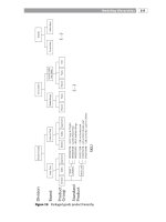
Figure 13-7 shows the directory structure of the CDS namespace. As you can
see, the namespace is organized in a hierarchical manner.
Figure 13-7 DCE: CDS namespace directory structure
Not all DCE names are stored directly in the DCE directory service. Resource
entries managed by some services, such as the security service (sec) and the
distributed file system (fs), connect into the namespace by means of specialized
CDS entries called junctions. A junction entry contains binding information that
enables a client to connect to a directory server outside of the directory service.
The security namespace is managed by the registry service of the DCE security
component, and the DFS namespace is managed by the file set location
database (FLDB) service of DFS.
Global Directory Service and Agent
The Cell Directory Service is responsible for knowing where resources are within
the cell. However, in a multicell network, each cell is part of a larger hierarchical
namespace, called the global directory namespace. The Global Directory
Service (GDS) enables us to resolve the location of resources in foreign cells.
This is the case when a company wants to connect their cells together or to the
Internet.
/ Global Root
/ : Local Root
cell-profile lan-profile hostname_ch
hosts subsys sec
fs
junction junction
hostname
config
self profile cds-clerk cds-server
dce
dfs
dfs sec
sec
500 TCP/IP Tutorial and Technical Overview
In order to find a resource in another cell, a communication path needs to exist
between the two cells. This communication path can currently be one of two
types:
CCITT X.500
Internet Domain Name Services (DNS)
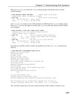
In order for intercell communications to be accomplished, another component,
the Global Directory Agent, is required. The Global Directory Agent (GDA) is the
intermediary between the local cell and the Global Directory Service. In
Figure 13-8, if the CDS does not know the location of a resource, it tells the client
to ask the GDA for assistance. The GDA knows to which global namespace it is
connected and queries the GDS (either DNS or X.500) for the name of the
foreign cell directory server with which to communicate. When in direct
communication with the foreign cell directory server, the network name of the
resource requested can be found. The Global Directory Agent is the component
that provides communications support for either DNS or X.500 environments.
Figure 13-8 DCE: Global Directory Agent
DCE security service
Security is always a concern in a networked environment. In a large, distributed
environment, it is even more crucial to ensure that all participants are valid users
who access only the data with which they are permitted to work. The two primary
concerns are authentication and authorization. Authentication is the process of
proving or confirming the identity of a user or service. Authorization is the
process of checking a user's level of authority when an access attempt is made.
For example, if a user tries to make a change when read-only access has been
granted, the update attempt will fail.
DNS
or X.500
CDS
GDA
Client
Cell A
CDS
GDA
Cell B