Computer Networking A Top-Down Approach Featuring the Internet phần 10 doc
Bạn đang xem bản rút gọn của tài liệu. Xem và tải ngay bản đầy đủ của tài liệu tại đây (9.88 MB, 75 trang )
What is Network Security?
7.8 Network Layer Security: IPsec
Having examined case studies of the use of various security mechanisms at the application, socket, and
transport layers, our final case study naturally takes us down to the network layer. Here, we'll examine the
the IP Security protocol, more commonly known as IPsec - a suite of protocols that provides security at
the network layer. IPsec is a rather complex animal, and different parts of it are described in more than a
dozen RFCs. In this section, we'll discuss IPsec in a specific context, namely, in the context that all hosts
in the Internet support IPsec. Although this context is many years away, the context will simplify the
discussion and help us understand the key features of IPsec. Two key RFCs are [RFC 2401], which
describes the overall IP security architecture and [RFC 2411], which provides an overview of the IPsec
protocol suite and the documents describing it. A nice introduction to IPsec is given in [Kessler].
Before getting into the specifics of IPsec, let's step back and consider what it means to provide security at
the network layer. Consider first what it means to provide network layer secrecy. The network layer
would provide secrecy if all data carried by all IP datagrams were encrypted. This means that whenever
a host wants to send a datagram, it encrypts the data field of the datagram before shipping it out into the
network. In principle, the encryption could be done with symmetric key encryption, public key encryption
or with session keys that have are negotiated using public key encryption. The data field could be a TCP
segment, a UDP segment, an ICMP message, etc. If such a network layer service were in place, all data
sent by hosts -- including e-mail, Web pages, control and management messages (such as ICMP and
SNMP) -- would be hidden from any third party that is "wire tapping" the network. (However, the
unencrypted data could be snooped at points in the source or destination hosts.) Thus, such a service
would provide a certain "blanket coverage" for all Internet traffic, thereby giving all of us a certain sense
of security.
In addition to secrecy, one might want the network layer to also provide source authentication. When a
destination host receives an IP datagram with a particular IP source address, it might authenticate the
source by making sure that the IP datagram was indeed generated by the host with that IP source address.
Such a service prevents attackers from spoofing IP addresses.
In the IPsec protocol suite there are two principal protocols: the Authentication Header (AH) protocol
and the Encapsulation Security Payload (ESP) protocol. When a source host sends secure datagrams to
a destination host, it does so with either the AH protocol or with the ESP protocol.The AH protocol
provides source authentication and data integrity but does not provide secrecy. The ESP protocol provides
data integrity and secrecy. Providing more services, the ESP protocol is naturally more complicated and
requires more processing than the AH protocol. We'll discuss both of these protocols below.
For both the AH and the ESP protocols, before sending secured datagrams from a source host to a
destination host, the source and network hosts handshake and create a network layer logical connection.
This logical channel is called a security agreement (SA). Thus, IPsec transforms the traditional
file:///D|/Downloads/Livros/computaỗóo/Computer%20Net...own%20Approach%20Featuring%20the%20Internet/IPsec.htm (1 of 5)20/11/2004 15:53:10
What is Network Security?
connectionless network layer of the Internet to a layer with logical connections! The logical connection
defined by a SA is a simplex connection, that is, it is unidirectional. If both hosts want to send secure
datagrams to each other, then two SAs (i.e., logical connections) need to be established, one in each
direction. A SA is uniquely identified by a 3-tuple consisting of:
q
q
q
a security protocol (AH or ESP) identifier;
the source IP address for the simplex connection;
a 32-bit connection identifier called the Security Paramter Index (SPI).
For a given SA (that is, a given logical connection from source host to destination host), each IPsec
datagram will have a special field for the SPI. All of the datagrams in the SA will use the same SPI value
in this field.
Authentication Header (AH) Protocol
As mentioned above, the AH protocol provides source host identification and data integrity but not
secrecy. When a particular source host wants to send one or more datagrams to a particular destination, it
first establishes an SA with the destination. After having established the SA, the source can send secured
datagrams to the destination host. The secured datagrams include the AH header, which is inserted
between the original IP datagram data (e.g., a TCP or UDP segment) and the IP header, as shown in
Figure 7.8-1. Thus the AH header augments the original data field, and this augmented data field is
encapsulated as a standard IP datagram. For the protocol field in the IP header, the value 51 is used to
indicate that the datagram includes an AH header. When the destination host recieves the IP datagram, it
takes note of the 51 in the protocol field, and processes the datagram using the AH protocol. (Recall that
the protocol field in the IP datagram is traditionally used to distinguish between UDP, TCP, ICMP, etc.)
Intermediate routers process the datagrams just as they always have -- they examine the destination IP
address and route the datagrams accordingly.
Figure 7.8-1: Position of the AH header in the IP datagram.
The AH header includes several fields, including:
q
Next Header field, which has the role that the protocol field has for an ordinary datagram. It
indicates if the data following the AH header is a TCP segment, UDP segment, ICMP segment,
file:///D|/Downloads/Livros/computaỗóo/Computer%20Net...own%20Approach%20Featuring%20the%20Internet/IPsec.htm (2 of 5)20/11/2004 15:53:10
What is Network Security?
q
q
q
etc. (Recall that protocol field in the datagram is now being used to indicate the AH protocol, so it
can no longer be used to indicate the transport-layer protocol.)
Security Parameter Index (SPI) field, an arbitrary 32-bit value that, in combination with the
destination IP address and the security protocol, uniquely identifies the SA for the datagram.
Sequence Number field, a 32-bit field containing a sequence number for each datagram. It is
initally set to 0 at the establishment of an SA. The AH protocol uses the sequence numbers to
prevent playback and man-in-the-middle attacks (see Section 7.3).
Authentication Data field, a variable-length field containing signed message digest (i.e., a digital
signature) for this packet. The message digist is calculated over the original IP datagram, thereby
providing source host authentication and IP datagram integrity. The digital signature is computed
using the authentication algorithm specified by the SA, such as DES, MD5 or SHA.
When the destination host receives an IP datagram with an AH header, it determines the SA for the packet
and then authenticates the integrity of the datagram by processing the authentication data field. The IPsec
authentication scheme (for both the AH and ESP protocols) uses a scheme called HMAC, which is an
encrypted message digest described in [RFC 2104]. HMAC uses a shared secret key between two parties
rather than public key methods for message authentication. Further details about the AH protocol can be
found in [RFC 2402].
The ESP Protocol
The ESP protocol provides network layer secrecy as well as source host authentication. Once again, it all
begins with a source host establishing a SA with a destination host. Then the source host can send secured
datagrams to the destination host. As shown in Figure 7.8-2, a secured datagram is created by surrounding
the original IP datagram data with header and trailer fields, and then inserting this encapsulated data into
the data field of an IP datagram. For the protocol field in the header of the IP datagram, the value 50 is
used to indicate that the datagram includes an ESP header and trailer. When the destination host recieves
the IP datagram, it takes note of the 50 in the protocol field, and processes the datagram using the ESP
protocol. As shown in Figure 7.8-2, the original IP datagram data along with the ESP Trailer field are
encrypted. Secrecy is provided with DES-CBC encryption [RFC 2405]. The ESP header consists of a 32bit field for the SPI and 32-bit field for the sequence number, which have exactly the same role as in the
AH protocol. The trailer includes the Next Header field, which also has exactly the same role. Note that
because the Next Header field is encrypted along with the original data, an intruder will not be able to
determine the transport protocol that is being used. Following the trailer there is the Authentication Data
field, which again serves the same role as in the AH protocol. Further details about the AH protocol can
be found in [RFC 2406].
file:///D|/Downloads/Livros/computaỗóo/Computer%20Net...own%20Approach%20Featuring%20the%20Internet/IPsec.htm (3 of 5)20/11/2004 15:53:10
What is Network Security?
Figure 7.8-2: The ESP fields in the IP datagram.
SA and Key Management
For sucessful deployment of IPsec, a scalable and automated SA and key management scheme is
necessary. Several protocols have been defined for these tasks, including:
q
q
The Internet Key Exchange (IKE) algorithm [RFC 2409] is the default key management protocol
for IPsec.
The Internet Security Assoication and Key Management Protocol (ISKMP) defines procedures for
establishing and tearing down SAs [RFC 2407] [RFC 2408]. ISKMP's security association is
completely separate from IKE key exchange.
This wraps up our summary of IPsec. We have discussed IPsec in the context of IPv4 and the "transport
mode". IPsec also defines a "tunnel mode," in which routers introduce the security functionality rather
than the hosts. Finally, IPsec describes encryption procedures for IPv6 as well as IPv4.
References
[Kessler] G.C. Kessler, An Overview of Cryptography, May 1998, Hill Associates, />TechLibrary/index.htm
[RFC 2104] H. Krawczyk, M.Bellare, R. Canetti, HMAC: Keyed-Hashing for Message Authentication,
[RFC 2104], February 1997.
[RFC 2401] S. Kent and R. Atkinson, Security Architecture for the Internet Protocol, [RFC 2401],
November 1998.
file:///D|/Downloads/Livros/computaỗóo/Computer%20Net...own%20Approach%20Featuring%20the%20Internet/IPsec.htm (4 of 5)20/11/2004 15:53:10
What is Network Security?
[RFC 2402] S. Kent and R. Atkinson, IP Authentication Header, [RFC 2402], November 1998.
[RFC 2405] C. Madson and N.Doraswamy, The ESP DES-CBC Cipher Algorithm with Explicit IV, [RFC
2405], November 1998.
[RFC 2406] S. Kent and R. Atkinson, IP Authentication Header, [RFC 2406], November 1998.
[RFC 2407] D. Piper, The Internet IP Security Domain of Interpretation for ISAKMP, [RFC 2407],
November 1998
[RFC 2408] D. Maughan, M. Schertler, M. Schneider and J. Turner, Internet Security Association and
Key Management Protocol (ISAKMP), [RFC 2408], November 1998.
[RFC 2409] D. Harkins and D. Carrel, The Internet Key Exchange (IKE), [RFC 2409], November 1998
[RFC 2411] R. Thayer, N. Doraswamy and R. Glenn, "IP Security Document Road Map," [RFC 2411],
November 1998
Copyright 1999-2000 . Keith W. Ross and Jim Kurose. All rights reserved.
file:///D|/Downloads/Livros/computaỗóo/Computer%20Net...own%20Approach%20Featuring%20the%20Internet/IPsec.htm (5 of 5)20/11/2004 15:53:10
Chapter 7 summary
7.9 Summary
In this chapter, we've examined the various mechanisms that our secret lovers, Bob and Alice, can use to
communicate "securely." We've seen that Bob and Alice are interested in secrecy (so that they alone are
able to understand the contents of a transmitted message), authentication (so that they are sure that they
are talking with each other), and message integrity (so that they are sure that their messages are not
altered in transit). Of course, the need for secure communication is not confined to secret lovers. Indeed,
we saw in section 7.1 that security is needed at various layers in a network architecture to protect against
"bad guys" who may sniff packets, remove packets from the network, or inject falsely addressed packets
into the network.
The first part of this chapter presented various principles underlying secure communication. We
covered cryptographic techniques for coding and decoding data in Section 7.2, including both symmetric
key cryptography and public key cryptography. DES and RSA were examined as specific case studies
of these two major classes of cryptographic techniques in use in today's networks. In section 7.3 we
turned our attention to authentication, and developed a series of increasingly sophisticated
authentication protocols to ensure that a conversant is indeed who he/she claims to be, and is "live." We
saw that both symmetric key cryptography and public key cryptography can play an important role not
only in disguising data (encryption/decryption), but also in performing authentication. Techniques for
"signing" a digital document in a manner that is verifiable, non-forgible, and non-repudiable were
covered in Section 7.4. Once again, the application of cryptographic techniques proved essential. We
examined both digital signatures and message digests - a shorthand way of signing a digital document.
In section 7.5 we examined key distribution protocols. We saw that for symmetric key encryption, a
key distribution center - a single trusted network entity - can be used to distribute a shared symmetric
key among communicating parties. For public key encryption, a certification authority distributes
certificates to validate public keys.
Armed with the techniques covered in sections 7.2 through 7.5, Bob and Alice can communicate
securely (one can only hope that they are networking students who have learned this material and can
thus avoid having their tryst uncovered by Trudy!). In the second part of this chapter we thus turned our
attention to the use of various security techniques in networks. In section 7.6, we used e-mail as a case
study for application-layer security, designing an e-mail system that provided secrecy, sender
authentication and message integrity. We also examined the use of pgp as a public-key e-mail
encryption scheme. Our cases studies continued as we headed down the protocol stack and examined
the secure sockets layer (SSL) and secure electronic transactions, the two primary protocols in use today
for secure electronic commerce. Both are based on public key techniques. Finally, in section 7.8 we
examined a suite of security protocols for the IP layer of the Internet - the so-called IPsec protocols.
These can be used to provide secrecy, authentication and message integrity between two communication
IP devices.
file:///D|/Downloads/Livros/computaỗóo/Computer%20Networki...Approach%20Featuring%20the%20Internet/security_summary.htm20/11/2004 15:53:10
Network Security - Homework Problems
Homework Problems and Discussion Questions
Review Questions
1.) What are the differences between message secrecy and message integrity? Can you have one
without the other? Justify your answer.
2.) What is the difference between an active and a passive intruder?
3.) What is an important difference between a symmetric key system and a public key system?
4.) Suppose that an intruder has an encrypted message as well as the decrypted version of that message.
Can the intruder mount a cipher-text only attack, a known-plaintext or a chosen-plaintext attack?
5.) Suppose N people want to communicate with each of the N-1 other people using symmetric key
encryption. All communication between any to people, i and j, is visible to all other people, and no
other person should be able to decode their communication. How many keys are required in the system
as a whole? Now suppose that public key encryption is used. How many keys are required in this case?
6.) What is the purpose of a nonce in an authentication protocol?
7.) What does it mean to say that a nonce is a once-in-a-lifetime value? In whose lifetime?
8.) What is the man-in-the-middle attack? Can this attack occur when symmetric keys are used?
9.) What does it mean for a signed document to be verifiable, non-forgible, and non-repudiable?
10.) In what way does a message digest provide a better message integrity check than a checksum such
as the Internet checksum?
11.) In what way does a message digest provide a "better" digital signature than using a public key
digital signature?
12.) Is the message associated with a message digested encrypted? Since either "yes" or "no" are
acceptable answers here, you should explain your answer.
13.) What is a key distribution center? What is a certification authority?
14.) Summarize the key differences in the services provided by the Authentication Header protocol and
file:///D|/Downloads/Livros/computaỗóo/Computer%20Netw...ach%20Featuring%20the%20Internet/security_homework.htm (1 of 3)20/11/2004 15:53:11
Network Security - Homework Problems
the Encapsulation Security Payload (ESP) protocol in IPsec.
Problems
1.) Using the monoalphabetic cipher in Figure 7-3. Encode the message "This is an easy problem."
Decode the message "rmij'u uamu xyj."
2.) Show that Eve's known plaintext attack in which she knows the (ciphertext, plaintext) translation
pairs for seven letters reduces the number of possible substitutions to be checked by approximately 109.
3.) Consider the Vigenere system shown in Figure 7-4. Will a chosen plaintext attack that is able to get
the plaintext encoding of the message, "The quick fox jumps over the lazy brown dog" be sufficient to
decode all messages? Why?
4.) Using RSA, choose p = 3 and q = 11, and encode the phrase "hello". Apply the decryption
algorithm, to the encrypted version to recover the original plaintext message.
5.) In the man-in-the-middle attack in Figure 7.3-7, Alice has not authenticated Bob. If Alice were to
require Bob to authenticate himself using ap5.0, would the man-in-the-middle attack be avoided?
Explain your reasoning.
6.) The Internet BGP routing protocol uses the MD5 message digest rather than public key encryption to
sign BGP messages. Why do you think MD5 was chosen over public key encryption?
7.) Compute a third message, different than the two messages in Figure 7.4-5, that has the same
checksum as the messages in Figure 7.4-5.
8.) Augment the KDC protocol shown in Figure 7.5-1 to include the necessary authentication messages.
Be sure to show the use of nonces and indicate which key values are used to encrypt which messages
9.) In the protocol and discussion of Figure 7.5-1, why doesn't Alice have to explicitly authenticate Bob?
10.) In the protocol in Figure 7.5-2, Alice did not include her own identity in the message to the CA.
Anyone could thus spoof a message from Alice to the CA. Does this compromise the integrity of the
CA's public key distribution? Justify your answer.
11.) Why is there no explicit authentication in the protocol in Figure 7.5-2 ? Is authentication needed?
Why?
12.) Consider the KDC and the CA servers. Suppose a KDC goes down? What is the impact on the
ability of parties to communicate securely, i.e., who can, and can not, communicate? Justify your
file:///D|/Downloads/Livros/computaỗóo/Computer%20Netw...ach%20Featuring%20the%20Internet/security_homework.htm (2 of 3)20/11/2004 15:53:11
Network Security - Homework Problems
answer. Suppose now that a CA goes down. What is the impact of this failure?
Discussion Questions
1.) Suppose that an intruder could both insert and remove DNS messages into the network. Give three
scenarios showing the problems that such an intruder could cause.
2.) No one has formally "proven" that 3-DES or RSA are "secure." Given this, what evidence do we
have they are indeed secure?
3.) If IPsec provides security at the network layer, why is it that security mechanisms are still needed at
layers above IP?
4.) Go to the International PGP homepage ( What version of pgp are you legally
allowed to download, given the country you are in?
file:///D|/Downloads/Livros/computaỗóo/Computer%20Netw...ach%20Featuring%20the%20Internet/security_homework.htm (3 of 3)20/11/2004 15:53:11
Network Managment - Introduction
8.1 What is Network Management?
Having made our way through the first seven chapters of this text, we're now well aware that a network
consists of many complex, interacting pieces of hardware and software - from the links, bridges, routers,
hosts and other devices that comprise the physical components of the network to the many protocols (in
both hardware and software) that control and coordinate these devices. When hundreds or thousands of
such components are cobbled together by an organization to form a network, it is not surprising that
components will occasionally malfunction, that network elements will be misconfigured, that network
resources will be overutilized, or that network components will simply "break" (e.g., a cable will be cut,
a can of soda will be spilled on top of router). The network administrator, whose job it is to keep the
network "up and running," must be able to respond to (and better yet, avoid) such mishaps. With
potentially thousands of network components spread out over a wide area, the network administrator in a
network operations center (NOC) clearly needs tools to help monitor, manage, and control the network.
In this chapter, we'll examine the architecture, protocols, and information base used by a network
administrator in this task.
Before diving in to network management itself, let's first consider a few illustrative "real-world" nonnetworking scenarios in which a complex system with many interacting components must monitored,
managed, and controlled by an administrator. Electrical power-generation plants (at least as portrayed in
the popular media, e.g., movies such as the China Syndrome) have a control room where dials, gauges,
and lights monitor the status (temperature, pressure, flow) of remote valves, pipes, vessels, and other
plant components. These devices allow the operator to monitor the plant's many components, and may
alert the operator (the famous flashing red warning light) when trouble is imminent. Actions are taken by
the plant operator to control these components. Similarly, an airplane cockpit is instrumented to allow a
pilot to monitor and control the many components that make up an airplane. In these two examples, the
"administrator" monitors remote devices and analyzes their data to ensure that they are operational and
operating within prescribed limits (e.g., that a core meltdown of a nuclear power plant is not imminent,
or that the plane is not about to run out of fuel), reactively controls the system by making adjustments in
response the changes within the system or its environment, and proactively manages the system, e.g., by
detecting trends or anomalous behavior that allows action to be taken before serious problems arise. In a
similar sense, the network administrator will actively monitor, manage and control the system with
which s/he is entrusted.
In the early days of networking, when computer networks were research artifacts rather than a critical
infrastructure used by millions of people a day, "network management" was an unheard of thing. If one
encountered a network problem, one might run a few pings to locate the source of the problem and then
modify system settings, reboot hardware or software, or call a remote colleague to do so. (A very
readable discussion of the first major "crash" of the ARPAnet on October 27, 1980, long before network
management tools were available, and the efforts taken to recover from and understand the crash is
[RFC 789]). As the public Internet and private intranets have grown from small networks into a large
global infrastructure, the need to more systematically manage the huge number of hardware and
file:///D|/Downloads/Livros/computaỗóo/Computer%20Netw...pproach%20Featuring%20the%20Internet/netman_intro.html (1 of 5)20/11/2004 15:53:11
Network Managment - Introduction
software components within these networks has grown more important as well.
Figure 8.1-1: A simple scenario illustrating the uses of network management
In order to motivate our study of network management, let's begin with a simple example. Figure 8.1-1
illustrates a small network consisting of three routers, and a number of hosts and servers. Even in such a
simple network, there are many scenarios in which a network administrator might benefit tremendously
from having appropriate network management tools:
q
q
Failure of an interface card at a host (e.g., H1) or a router (e.g., A). With appropriate network
management tools, a network entity (e.g. router A) may report to the network administrator that
one of its interfaces has gone down (which is certainly preferable than a phone call to the NOC
from an irate user who says the network connection is down). A network administrator who
actively monitors and analyzes network traffic may be able to really impress the would-be irate
user by actually detecting problems in the interface ahead of time and replacing the interface card
before it fails. This could be done, for example, if the administrator noted an increase in
checksum errors in frames being sent by the soon-to-die interface.
Monitoring traffic to aid in resource deployment. A network administrator might monitor sourceto-destination traffic patterns and notice, for example, that by switching servers between LAN
segments, the amount of traffic that crosses multiple LANs could be significantly decreased.
Imagine the happiness all around (especially in higher administration) when better performance is
achieved with no new equipment costs. Similarly, by monitoring link utilization, a network
administrator might determine that a LAN segment, or the external link to the outside world is
overloaded and a higher-bandwidth link should thus be provisioned (alas, at an increased cost).
file:///D|/Downloads/Livros/computaỗóo/Computer%20Netw...pproach%20Featuring%20the%20Internet/netman_intro.html (2 of 5)20/11/2004 15:53:11
Network Managment - Introduction
The network administrator might also want to be notified automatically when congestion levels
on a link exceed a given threshold value in order to address a provisioning problem before it
becomes serious.
q
q
q
Detecting rapid changes in routing tables. Route flapping - frequent changes in the routing tables
- may indicate instabilities in the routing or a misconfigured router. Certainly, the network
administrator who has improperly configured a router would prefer to discover the error his/
herself, before the network goes down.
Monitoring for SLAs. With the advent of Service Level Agreements (SLA) - contracts that
define specific performance metrics and acceptable levels of network provider performance with
respect to these metrics - interest in traffic monitoring has increased significantly over the past
few years [Larsen 1997]. UUnet and AT&T are just two of many many network providers that
guarantee SLAs [UUNet 1999, AT&T 1998] to their customers. These SLAs include service
availability (outage), latency, throughput and outage notification requirements. Clearly, if
performance criteria are to be part of a service agreement between a network provider and its
users, then measuring and managing performance will be of great importance to the network
administrator.
Intrusion detection. A network administrator may want to be notified when network traffic
arrives from, or is destined to, a suspicious source (e.g., host or port number). Similarly, a
network administrator may want to detect (and in many cases filter) the existence of certain types
of traffic (e.g., source-routed packets, or a large number of SYN packets directed to a given host)
that are known to be characteristic of certain attacks.
The ISO, the organization that gave us the well-known 7-layer ISO reference model (see Chapter 1), has
also created a network management model, that is useful for placing the above anecdotal scenarios in a
more structured framework. Five areas of network management are defined:
q
q
Performance management. The goal of performance management is to quantify, measure,
report, analyze and control the performance (e.g., utilization, throughput) of different network
components. These components include individual devices (e.g., links, routers, and hosts) as
well as end-end abstractions such as a path through the network. We will see shortly that protocol
standards such as the Simple Network Management Protocol (SNMP) [RFC 2570] play a central
role in performance management.
Fault management. The goal of fault management is to log, detect, and respond to fault
conditions in the network. The line between fault management and performance management is
rather blurred. We can think of fault management as the immediate handling of transient network
failures (e.g., link, host or router hardware or software outages), while performance management
takes the longer term view of providing acceptable levels of performance in the face of varying
traffic demands and (hopefully rare) network device failures. As with performance management,
file:///D|/Downloads/Livros/computaỗóo/Computer%20Netw...pproach%20Featuring%20the%20Internet/netman_intro.html (3 of 5)20/11/2004 15:53:11
Network Managment - Introduction
the SNMP protocol plays a central role in fault management of IP networks.
q
q
q
Configuration management. Configuration management allows a network manager to track
which devices are on the managed network and the hardware and software configurations of
these devices.
Accounting management. Accounting management allows the network manager to specify, log,
and control user and device access to network resources. Usage quotas, usage-based charging,
and the allocation of resource access privileges all fall under accounting management.
Security management. The goal of security management is to control access to network
resources according to some well-defined policy. The key distribution centers and certificate
authorities that we studied in section 7.4 are components of security management. The use of
firewalls to monitor and control external access points to one's network, a topic we will study in
section 8.4, is another crucial component.
In this chapter, we'll cover only the rudiments of network management. Our focus will be purposefully
narrow - we'll examine only the infrastructure for network management - the overall architecture,
network management protocols, and information base through which a network administrator "keeps the
network up and running." We'll not cover the decision making processes of the network administrator,
who must plan, analyze, and respond to the management information that is conveyed to the NOC. In
this area, topics such as fault identification and management [Katzela 1995, Mehdi 1997], proactive
anomaly detection [Thottan 1998], alarm correlation [Jakobson 1993], and more come into
consideration. Nor will we cover the broader topic of service management [Saydam 1996] - the
provisioning of resources such as bandwidth, server capacity and the other computational/
communication resources needed to meet the mission-specific service requirements of an enterprise. In
this latter area, standards such as TMN [Glitho 1995, Sidor 98] and TINA [Hamada 1997] are larger,
more encompassing (and arguably much more cumbersome) standards that address this larger issue.
TINA, for example, is described as "a set of common goals, principles, and concepts cover the
management of services, resources, and parts of the Distributed Processing Environment" [Hamada
1997]. Clearly, all of these topics are enough for a separate text, and would take us a bit far afield from
the more technical aspects of computer networking. So, as noted above, our more modest goal here will
be cover the important "nuts and bolts" of the infrastructure through which the network administrator
keeps the bits flowing smoothly
An often-asked question is "What is network management?" Our discussion above has motivated the
need for, and illustrated a few of the uses of, network management. We'll conclude this section with a
single-sentence (albeit a rather long, run-on sentence) definition of network management from [Saydam
1996]:
"Network management includes the deployment, integration and coordination of the hardware,
software and human elements to monitor, test, poll, configure, analyze, evaluate and control the
file:///D|/Downloads/Livros/computaỗóo/Computer%20Netw...pproach%20Featuring%20the%20Internet/netman_intro.html (4 of 5)20/11/2004 15:53:11
Network Managment - Introduction
network and element resources to meet the real-time, operational performance, and Quality of
Service requirements at a reasonable cost."
It's a mouthful, but it's a good workable definition. In the following sections, we'll add some meat to
this rather bare-bones definition of network management.
References
[AT&T 1999] AT&T, "AT&T raises the bar on data networking guarantees," />press/0198/980127.bsc.html
[Glitho 1995] R. Glitho and S. Hayes (eds.) , special issue on Telecommunications Management
Network, IEEE Communications Magazine, Vol. 33, No. 3, (March 1995).
[Hamada 1997] T. Hamada, H. Kamata, S. Hogg, "An Overview of the TINA Management
Architecture," Journal of Network and Systems Management, Vol. 5. No. 4 (Dec. 1997). pp. 411-435.
[Jakobson 1993] G. Jacobson and M. Weissman, "Alarm Correlation," IEEE Network Magazine, 1993,
pp. 52-59.
[Katzela 1995] I. Katzela, and M. Schwartz. "Schemes for Fault Identification in Communication
Networks," IEEE/ACM Transactions on Networking, Vol. 3, No. 6 (Dec. 1995), pp. 753-764.
[Larsen 1997] A. Larsen, "Guaranteed Service: Monitoring Tools," Data Communications, June 1997,
pp. 85-94.
[Mehdi 1997] D. Mehdi and D. Tipper (eds.), Special Issue: Fault Management in Communication
Networks, Journal of Network and Systems Management, Vol. 5. No. 2 (June 1997).
[RFC 789] E. Rosen, "Vulnerabilities of Network Control Protocols," RFC 789.
[RFC 2570] J. Case, R. Mundy, D. Partain, B. Stewart, "Introduction to Version 3 of the Internetstandard Network Management Framework" RFC 2570, May 1999.
[Saydam 1996] T. Saydam and T. Magedanz, "From Networks and Network Management into Service
and Service Management," Journal of Networks and System Management, Vol. 4, No. 4 (Dec. 1996),
pp. 345-348.
[Sidor 1998] D. Sidor, TMN Standards: Satisfying Today's Needs While Preparing for Tomorrow, IEEE
Communications Magazine, Vol. 36, No. 3 (March 1998), pp. 54-64.
[Thottan 1998] M. Thottan and C. Ji, "Proactive Anomaly Detection Using Distributed Intelligent
Agents," IEEE Network Magazine, Vol. 12, No. 5 (Sept./Oct. 1998), pp. 21-28.
[UUnet 1999] UUnet, "Service Level Agreement," />
Copyright 1999. James F. Kurose and Keith W. Ross. All Rights Reserved.
file:///D|/Downloads/Livros/computaỗóo/Computer%20Netw...pproach%20Featuring%20the%20Internet/netman_intro.html (5 of 5)20/11/2004 15:53:11
The Infrastrcuture for Network management
8.2 The Infrastructure for Network Management
We've seen in the previous section that network management requires the ability to "monitor, test, poll,
configure, ... and control" the hardware and software and components in a network. Because the
network devices are distributed, this will minimally require that the network administrator be able to
gather data (e.g., for monitoring purposes) from a remote entity and be able to affect changes (e.g.,
control) at that remote entity. A human analogy will prove useful here for understanding the
infrastructure needed for network management.
Imagine that you're the head of a large organization that has branch offices around the world. It's your
job to make sure that the pieces of your organization are operating smoothly. How would you do so? At
a minimum, you'll periodically gather data from your branch offices in the form of reports and various
quantitative measures of activity, productivity, and budget. You'll occasionally (but not always) be
explicitly notified when there's a problem in one of the branch offices; the branch manager who wants to
climb the corporate ladder (perhaps to get your job) may send you unsolicited reports indicating how
smoothly things are running at his/her branch. You'll sift through the reports you receive, hoping to find
smooth operations everywhere, but no doubt finding problems in need of your attention. You might
initiate a one-on-one dialogue with one of your problem branch offices, gather more data in order to
understand the problem, and then pass down an executive order ("Make this change!") to the branch
office manager. Implicit in this very common human scenario is an infrastructure for controlling the
organization - the boss (you), the remotes sites being controlled (the branch offices), your remote agents
(the branch office managers), communication protocols (for transmitting standard reports and data, and
for one-on-one dialogues), and data (the report contents and the quantitative measures of activity,
productivity, and budget). Each of these components in human organizational management has an exact
counterpart in network management.
The architecture of a network management system is conceptually identical to this simple human
organizational analogy. The network management field has its own specific terminology for the various
components of a network management architecture, and so we adopt that terminology here. As shown
in Figure 8.2-1, there are three principle components of a network management architecture: a managing
entity (e.g., the boss in our above analogy - you), the managed devices (the branch office), and a
network management protocol.
file:///D|/Downloads/Livros/computaỗóo/Computer%20Netwo...pproach%20Featuring%20the%20Internet/infrastructure.htm (1 of 4)20/11/2004 15:53:12
The Infrastrcuture for Network management
Figure 8.2-1: principal components of a network management architecture
q
q
The managing entity is an application, typically with a human-in-the-loop, running in a
centralized network management station in the network operations center (NOC). The managing
entity is the central locus of activity for network management - it controls the collection,
processing, analysis, and/or display of network management information. It is here that actions
are initiated to control network behavior and here that the human network administrator interacts
with the network devices.
A managed device is a piece of network equipment (including its software) that resides on a
managed network. This is the branch office in our human analogy. A managed device might be a
host, router, bridge, hub, printer, or modem device. Within a managed device, there may be
several so-called managed objects. These managed objects are the actual pieces of hardware
within the managed device (e.g., a network interface card), and the sets of configuration
parameters for the pieces of hardware and software (e.g., an intradomain routing protocol such as
RIP). In our human analogy, the managed objects might be the departments within the branch
office. These managed objects have pieces information associated with them that are collected
into a management information base (MIB); we'll see that the values of these pieces of
information are available to (and in many cases setable by) the managing entity. In our human
file:///D|/Downloads/Livros/computaỗóo/Computer%20Netwo...pproach%20Featuring%20the%20Internet/infrastructure.htm (2 of 4)20/11/2004 15:53:12
The Infrastrcuture for Network management
analogy, the MIB corresponds to quantitative data (measures of activity, productivity, and
budget, with the latter being setable by the managing entity!) exchanged between the branch
office and the main office. We'll study MIBs in detail in section 8.3. Finally, also resident in
each managed device is a network management agent, a process running in the managed
device that communicates with the managing entity, taking local actions on the managed device
under the command and control of the managing entity. The network management agent is the
branch manager in our human analogy.
q
The third piece of a network management architecture is the network management protocol.
The protocol runs between the managing entity and the managed devices, allowing the managing
entity to query the status of managed devices and indirectly effect actions in these devices via its
agents. Agents can use the the network management protocol to inform the managing entity of
exceptional events (e.g., component failures or violation of performance thresholds).
Although the infrastructure for network management is conceptually simple, one can often get bogged
down with the network-management-speak vocabulary of "managing entity," "managed device,"
"managing agent," and "management information base." Hopefully, keeping the human organizational
analogy and its obvious parallels with network management in mind will be of help as we continue
through this chapter.
Our discussion of network management architecture above has been generic, and broadly applied to a
number of the network management standards and efforts that have been proposed over the years.
Network management standards began maturing in the late 1980's, with OSI CMISE/CMIP (the
Common Management Service Element/Common Management Information Protocol) [Piscatello
1993, Stallings 1993, Glitho 1998] and the Internet SNMP (Simple Network Management Protocol)
[Stallings 1993, RFC 2570, Stallings 1999, Rose 1996] emerging as the two most important standards.
Both are designed to be independent of vendor-specific products or networks. Because SNMP was
quickly designed and deployed at a time when the need for network management was becoming
painfully clear, SNMP found widespread use and acceptance. Today, SNMP has emerged as the most
widely used and deployed network management framework. We cover SNMP in detail in the following
section
References
[Glitho 1998] R. Glitho, "Contrasting OSI Systems Management to SNMP and TMN," Journal of
Network and Systems Management, Vol. 6, No. 2, (June 1998), pp. 113-131.
[Piscatello 1993] D. Piscatello and A. Lyman Chapin, "Open Systems Networking", Addison Wesley,
1993.
[RFC 2570] J. Case, R. Mundy, D. Partain, B. Stewart, "Introduction to Version 3 of the Internetstandard Network Management Framework" RFC 2570, May 1999.
[Rose 1996] M. Rose, "Simple Book, The: An Introduction to Internet Management, Revised Second
Edition," Prentice Hall, 1996.
file:///D|/Downloads/Livros/computaỗóo/Computer%20Netwo...pproach%20Featuring%20the%20Internet/infrastructure.htm (3 of 4)20/11/2004 15:53:12
The Infrastrcuture for Network management
[Stallings 1993] W Stallings, "SNMP. SNMP v2. and CMIP The Practical Guide to Network
Management Standards," Addison Wesley 1993.
[Stallings 1999] W. Stallings, "Snmp, Snmpv2, Snmpv3, and Rmon 1 and 2," Addison Wesley, 1999.
Copyright 1999. James F. Kurose and Keith W. Ross. All Rights Reserved.
file:///D|/Downloads/Livros/computaỗóo/Computer%20Netwo...pproach%20Featuring%20the%20Internet/infrastructure.htm (4 of 4)20/11/2004 15:53:12
The Internet Network Management Framework
8.3 The Internet Network Management Framework
Contrary to what the name SNMP (Simple Network Management Protocol) might suggest, network
management in the Internet is much more than just a protocol for moving management data between a
management entity and its agents, and has grown to be more complex than the word "simple" might suggest.
The current Internet Standard Management Framework traces it roots back to the Simple Gateway Monitoring
Protocol , SGMP [RFC 1028]. that was designed by a group of university network researchers, users, and
manager; their experience with SGMP allowed them to design, implement, and deploy SNMP in just a few
months [Lynch 1993] - a far cry from today's rather drawn out standardization process. Since then, SNMP
has evolved from SNMPv1 through SNMPv2 to the most recent version, SNMPv3 [RFC2570], released in
April 1999.
When describing any framework for network management, certain questions must inevitably be addressed:
q
q
q
What (from a semantic viewpoint) is being monitored? And what form of control can be exercised by
the network administrator?
What is the specific form of the information that will be reported and/or exchanged?
What is the protocol for communication protocol for exchanging this information?
Recall our human organizational analogy from the previous section. The boss and the branch managers will
need to agree on the measures of activity, productivity and budget used to report the branch office's status.
Similarly, they'll need to agree on the actions the boss can take (e.g., cut budget, order the branch manager to
change some aspect of the office's operation). At a lower level of detail, they'll need to agree on the form in
which this data is reported (e.g., In what currency (dollars, euros?) will the budget be reported? In what units
will productivity be measured?). While these are trivial details, but they be agreed upon, nonetheless.
Finally, the manner in which information is conveyed between the main office and the branch offices (i.e.,
their communication protocol) must be specified.
The Internet Network Management Framework exactly addresses the the questions posed above. The
framework consists of four parts:
q
q
definitions of network management objects known as MIB objects. In the Internet network
management framework, management information is represented a collection of managed objects that
together form a virtual information store, known as the Management Information Base (MIB). A MIB
object might be a counter, such as the number of IP datagrams discarded at a router due to errors in an
IP datagram header or the number of carrier sense errors in an Ethernet interface, descriptive
information such as the server software running on a DNS server; status information such as whether
a particular device is functioning correctly or not, or protocol-specific information such as a routing
path to a destination. MIB objects thus define the management information maintained by a managed
node. Related MIB objects are gathered into so-called MIB modules. In our human organization
analogy, the MIB defines the information conveyed between the branch office and the main office.
a data definition language, known as SMI (Structure of Management Information) that defines the
file:///D|/Downloads/Livros/computaỗóo/Computer%20Ne...own%20Approach%20Featuring%20the%20Internet/snmp.htm (1 of 15)20/11/2004 15:53:15
The Internet Network Management Framework
q
q
data types, an object model, and rules for writing and revising management information; MIB objects
are specified in this data definition language. In our human organizational analogy, the SMI is used to
define the details of the format of the information to be exchanged.
a protocol, SNMP, for conveying information and commands between a managing entity and an agent
executing on behalf of that entity within a managed network device;
security and administration capabilities. The addition of these capabilities represents the major
enhancement in SNMPv3 over SNMPv2.
The Internet network management architecture is thus modular by design, with a protocol-independent data
definition language and MIB, and a MIB-independent protocol. Interestingly, this modular architecture was
first put in place to ease the transition from an SNMP-based network management to a network management
framework being developed by the International Organization for Standardization (ISO), the competing
network management architecture when SNMP was first conceived - a transition that never occurred. Over
time, however, SNMP's design modularity has allowed it to evolve through three major revisions, with each
of the four majors parts of SNMP discussed above evolving independently. Clearly, the right decision about
modularity was made, if even for the wrong reason!
In the following four sections, we cover the four major components of the Internet network management
framework in more detail.
8.3.1 Structure of Management Information: SMI
The Structure of Management Information, SMI, (a rather oddly named component of the network
management framework whose name gives no hint of its functionality) is the language used to define the
management information residing in a managed network entity. Such a definition language is needed to
ensure that the syntax and semantics of the defined network management data are well-defined and
unambiguous. Note that the SMI does not define a specific instance the data in a managed network entity, but
rather the language in which such information is specified. The documents describing the SMI for SNMPv3
(which rather confusingly, is called SMIv2) are [RFC 2578, RFC 2579, RFC 2580]. Let us examine the SMI
in a bottom-up manner, starting with the base data types in the SMI. We'll then look at how managed objects
are described in SMI, and then how related managed managed objects are grouped into modules.
SMI Base Data Types
RFC 2578 [RFC 2578] specifies the basic data types in the SMI MIB module-definition language. Although
the SMI is based on the ASN.1 (Abstract Syntax Notation One) [ISO 1987, ISO X.680] object definition
language (see section 8.4) developed by the ISO in the 1980, enough SMI-specific data types have been
added that SMI should be considered a data definition language in its own right. The eleven basic data types
defined in RFC 2578 are shown in Table 8.3-1. In addition to these scalar objects, it is also possible to
impose a tabular structure on an ordered collection of MIB objects using the SEQUENCE OF construct; see
[RFC 2578] for details. Most of the data types in Table 8.3-1 will be familiar (or self-explanatory) to most
readers. The one data type we will discuss in more detail shortly is the OBJECT IDENTIFIER data type,
which is used to name an object.
file:///D|/Downloads/Livros/computaỗóo/Computer%20Ne...own%20Approach%20Featuring%20the%20Internet/snmp.htm (2 of 15)20/11/2004 15:53:15
The Internet Network Management Framework
Data type
Description
INTEGER
32 bit integer, as defined in ASN.1, with a value between -2^31 and 2^31-1
inclusive, or a value from a list of possible named constant values
Integer32
32 bit integer with a value between -2^31 and 2^31-1 inclusive
Unsigned32
Unsigned 32 bit integer in the range 0 to 2^23-1 inclusive
OCTET STRING
ASN.1-format byte string representing arbitrary binary or textual data, up to 65535
bytes long
OBJECT IDENTIFIER ASN.1-format administratively assigned (structured name); see section 8.3
IPaddress
32-bit Internet address, in network byte order
Counter32
32-bit counter that increases from 0 to 2^32-1 and then wraps around to 0.
Counter64
64-bit counter
Gauge32
32-bit integer that will not count above 2^31-2 nor decrease beyond 0 when
increased or decreased
TimeTicks
time, measured in 1/100ths of seconds since some event
Opaque
uninterpreted ASN.1 string, needed for backward compatibility
Table 8.3-1: Basic data types of the SMI
SMI Higher Level Constructs
In addition to the basic data types, the SMI data definition language also provides higher level language
constructs:
q
The OBJECT-TYPE construct is used to specify the data type, status, and semantics of a managed
object. Collectively, these managed objects contain the management data that lies at the heart of
network management. There are nearly 10,000 defined objects in various Internet RFC's [RFC 2570].
The OBJECT-TYPE construct has four clauses. The SYNTAX clause of an OBJECT-TYPE definition
specifies the basic data type associated with the object. The MAX-ACCESS clause specifies whether
the managed object can be read, be written, be created, or have its value included in a notification.
The STATUS clause indicates whether object definition is current and valid, obsolete (in which case it
should not be implemented, as its definition is included for historical purposes only) or deprecated
(obsolete, but implementable for interoperability with older implementations). The DESCRIPTION
clause contains a human-readable textual definition of the object; this "documents" the purpose of the
managed object and should provide all the semantic information needed to implement the managed
object
As an example of the OBJECT-TYPE construct, consider the ipInDeliversobject type definition
from [RFC 2011]. This object defines a 32-bit counter which keeps track of the number of IP
file:///D|/Downloads/Livros/computaỗóo/Computer%20Ne...own%20Approach%20Featuring%20the%20Internet/snmp.htm (3 of 15)20/11/2004 15:53:15
The Internet Network Management Framework
datagrams that were received at the managed node and were successfully delivered to an upper layer
protocol. The final line of this definition is concerned with the name of this object, a topic we will
consider in the following section.
ipInDelivers OBJECT-TYPE
SYNTAX
Counter32
MAX-ACCESS read-only
STATUS
current
DESCRIPTION
"The total number of input datagrams
successfully delivered
to IP user-protocols (including ICMP)."
::= { ip 9 }
q
The MODULE-IDENTITY construct allows related objects to grouped together within a "module".
For example, [RFC 2011] specifies the MIB module that defines managed objects (including
ipInDelivers) for managing implementations of the Internet Protocol (IP) and its associated
Internet Control Message Protocol (ICMP). [RFC 2012] specifies the MIB module for TCP and [RFC
2013] specifies the MIB module for UDP. [RFC 2021] defines the MIB module for RMON remote
monitoring. In addition to containing the OBJECT-TYPE definitions of the managed objects within
the module, the MODULE-IDENTITY construct contains clauses to document contact information of
the author of the module, the date of the last update, a revision history, and a textual description of the
module. As an example, consider the module definition for management of the IP protocol:
ipMIB MODULE-IDENTITY
LAST-UPDATED "9411010000Z"
ORGANIZATION "IETF SNMPv2 Working Group"
CONTACT-INFO
"
Keith McCloghrie
Postal: Cisco Systems, Inc.
170 West Tasman Drive
San Jose, CA 95134-1706
US
Phone:
Email:
+1 408 526 5260
"
DESCRIPTION
"The MIB module for managing IP and ICMP
implementations,
but excluding their management of IP routes."
REVISION
"9103310000Z"
DESCRIPTION
file:///D|/Downloads/Livros/computaỗóo/Computer%20Ne...own%20Approach%20Featuring%20the%20Internet/snmp.htm (4 of 15)20/11/2004 15:53:15
The Internet Network Management Framework
"The initial revision of this MIB module was part
of MIBII."
::= { mib-2 48}
q
q
q
the NOTIFICATION-TYPE construct is used to specify information regarding "SNMPv2-Trap" and
"InformationRequest" messages generated by an agent, or a managing entity, see section 8.3. This
information includes a textual DESCRIPTION of when such messages are to be sent, as well as list of
values to be included in the message generated; see [RFC 2578] for details.
The MODULE-COMPLIANCE construct defines the set managed objects within a module that an
agent must implement.
The AGENT-CAPABILITIES construct specifies the capabilities of agents with respect to object and
event notification definitions.
8.3.2 Management Information Base: MIB
As noted above, the Management Information Base, MIB, can be thought of as a virtual information store,
holding managed objects whose values collectively reflect the current "state" of the network. These values
may be queried and/or set by a managing entity by sending SNMP messages to the agent that is executing in a
managed node on behalf of the managing entity. Managed objects are specified using the OBJECT-TYPE
SMI construct discussed above and gathered into MIB modules using the MODULE-IDENTITY construct.
The IETF has been busy standardizing the MIB modules (i.e., the management information) associated with
routers, hosts and other network equipment. This includes basic identification data about a particular piece of
hardware, and management information about the device's network interfaces and protocols. As of the release
of SNMPv3 (mid-1999), there were nearly 100 standards-based MIB modules and an even larger number of
vendor-specific (private) MIB modules. With all of these standards, the IETF needed a way to identify and
name the standardized modules, as well as the specific managed objects within a module. Rather than start
from scratch, the IETF adopted a standardized object identification (naming) framework that had already
been put in place by the International Organization for Standardization (ISO). As is the case with many
standards bodies, the ISO had "grand plans" for their standardized object identification framework - to
identify every possible standardized object (e.g., data format, protocol, or piece of information) in any
network, regardless of the network standards organization (e.g., Interne IETFt, ISO, IEEE, or ANSI),
equipment manufacturer, or network owner. A lofty goal indeed! The object identification framework
adopted by ISO is part of the ASN.1 (Abstract Syntax Notation One) [ISO 1987, ISO X.680] object definition
language (see section 8.4). Standardized MIB modules have their own cozy corner in the all encompassing
naming framework, as discussed below.
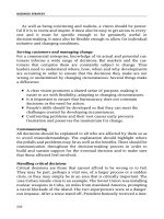
As shown in Figure 8.3-1, objects are identified in the ISO naming framework in a hierarchical manner. Note
that each branch point in the tree has both a name and a number (shown in parenthesis); any point in the tree
is thus identifiable by the sequence of names or numbers that specify the path from the root to that point in
the identifier tree. A fun, but incomplete and unofficial, WWW-based utility for traversing part of the object
file:///D|/Downloads/Livros/computaỗóo/Computer%20Ne...own%20Approach%20Featuring%20the%20Internet/snmp.htm (5 of 15)20/11/2004 15:53:15
The Internet Network Management Framework
identifier tree (using branch information contributed by volunteers) is />objectid/top.html.
Figure 8.3-1: ASN.1 Object Identifier Tree
file:///D|/Downloads/Livros/computaỗóo/Computer%20Ne...own%20Approach%20Featuring%20the%20Internet/snmp.htm (6 of 15)20/11/2004 15:53:15
The Internet Network Management Framework
At the top of the hierarchy are the International Organization for Standardization (ISO) and the
Telecommunication Standardization Sector of the International Telecommunication Union (ITU-T), the two
main standards organizations dealing with ASN.1, as well as a brach for joint efforts by these two
organizations. Under the ISO branch of the tree, we find entries for all ISO standards (1.0) and for standards
issued by standards bodies of various ISO-member countries (1.2). Although not shown in Figure 8.3-1,
under (ISO ISO-Member-Body, a.k.a. 1.2) we would find USA (1.2.840), under which we would find a
number of IEEE, ANSI, and company-specific standards. These include RSA (1.2.840.11359) and Microsoft
(1.2.840.113556), under which we find the Microsoft File Formats (1.2.840.112556.4) for various Microsoft
products, such as Word (1.2.840.11356.4.2). But we are interested here in networking (not Microsoft Word
files), so let us turn our attention to the branch labeled 1.3 - the standards issued by bodies recognized by the
ISO. These include the US Department of Defense (6) (under which we will find the Internet standards), the
Open Software Foundation (22), the airline association SITA (69) and NATO-identified bodies (57), as well
as many other organizations.
Under the Internet branch of the tree (1.3.6.1), there are seven categories. Under the private (1.3.6.1.4)
branch, we will find a list [IANA 1999b] of the names and private enterprise codes of more than 4000 private
companies that have registered with the Internet Assigned Numbers Authority (IANA) [IANA 99]. Under the
management (1.3.6.1.2) and MIB-2 branch (1.3.6.1.2.1) of the object identifier tree, we find the definitions
of the standardized MIB modules.
Standardized MIB modules
The lowest level of the tree in Figure 8.3-1 shows some of the important hardware-oriented MIB modules
(system and interface) as well as modules associated with some of the most important Internet
protocols. [RFC 2400] lists all of the standardized MIB modules. While MIB-related RFC's make for rather
tedious and dry reading, it is instructive (i.e., line eating vegetables, it is "good for you") to consider a few
MIB module definitions to get a flavor for the type of information in a module.
The managed objects falling under system contain general information about the device being managed; all
managed devices must support the system MIB objects. Table 8.3-2 defines the objects in the system group,
as defined in [RFC 1213].
Object Identifier Name
1.3.6.1.2.1.1.1
sysDescr
Type
Description (from RFC 1213)
OCTET STRING
"full name and version identification of the
system's hardware type, software operatingsystem, and networking software"
file:///D|/Downloads/Livros/computaỗóo/Computer%20Ne...own%20Approach%20Featuring%20the%20Internet/snmp.htm (7 of 15)20/11/2004 15:53:15