ccna practical cisco routers phần 9 docx
Bạn đang xem bản rút gọn của tài liệu. Xem và tải ngay bản đầy đủ của tài liệu tại đây (4.33 MB, 39 trang )
3 0 4
(Some of the high-end Cisco routers actually have complex cooling
systems and also enable you to monitor the temperature of the
device.)
PART IV Ad vanced Confi guration and Confi gurati on To o l s
CHAPTER 18 Basi c Router Tr o u b l e s h o o t i n g
FIGURE 18.2
The show
controller command
can be used to view sta-
tistics related to the con-
trollers installed on the
router.
In cases where the router crashes, it can be tough to determine if the
problem was hardware- or software-related. You can use the show
stacks command to retrieve error messages that were saved by the
ROM monitor at the time of the crash. (Cisco technical support rep-
resentatives can use the show stacks information to pinpoint the soft-
ware or hardware problem that caused the crash).
Besides the physical failure of router components, you might also run
into situations where the router doesn’t have enough RAM (or
processor speed) to really handle all the traffic that you have flowing
through it. You might need to add additional routers to the internet-
work to lighten the load or upgrade existing router hardware compo-
nents (such as RAM). In some cases you might want to upgrade from
the existing router to a higher-end router.
One way that network administrators identify bottlenecks on their
networks (a bottleneck is a device that is slowing network traffic) is to
use some type of network management software package that allows
the monitoring of devices, protocols, and other aspects of the net-
work and enables you to view the current health of your internet-
work. CiscoWorks is an example of a network management software
3 0 5
PART IV
Tro ublesh ooting Hardw are Pr oblems CHAPTER 18
package that provides a number of tools for monitoring and trou-
bleshooting internetworks. On large internetworks some sort of net-
work management software is vital for keeping tabs on the network
and its various devices.
Other Hardware Problems
Other hardware problems that will affect the job that your router is
doing relate to devices that are directly connected to the router.
On Ethernet networks, hubs are typically attached to an Ethernet
port on the router. If the hub goes down, the LAN’s connection to
the router also goes down, making node addresses on the LAN
unavailable to other nodes on the internetwork.
Hubs typically have a power on LED somewhere on the unit that
makes it easy for you to determine whether the hub is on or off. If
the hub is plugged in and turned on and still provides no indication
that the unit has powered up, replace the hub.
If you are having trouble with individual nodes on a LAN, hubs typi-
cally have an LED that lights when a particular port on the hub is
connected to a node via a twisted-pair cable. If the display light isn’t
on, you either have a bad cable (see the next section concerning
cabling and LAN connections) or the port on the hub is bad.
The same types of problems can be associated with router connec-
tions to Token Ring networks. A Token Ring Multi-Station Access
Unit will be attached to the router providing the connection between
the nodes on the LAN and the router. If the Access Unit goes down,
the LAN’s connection to the router will be disrupted.
WAN connectivity devices can also pose potential problems to the
internetwork. Routers are often connected to CSU/DSUs that pro-
vide connectivity to certain WAN technologies such as leased lines
and packet-switching network. If the CSU/DSU goes down, the
WAN connection between the router and the rest of the internet-
work also goes down.
If the hardware problem is related to your service provider’s switch-
ing equipment there is little that you can do to fix the problem your-
self. You have to sit and wait for the connection to come back up. In
many cases, network administrators will build fault tolerance into an
Approach your
troubleshooting
systematically
Whether you are
troubleshooting hardware
or software problems,
approach the problem sys-
tematically. First identify
the problem, and then
gather facts related to the
problem. You can use vari-
ous router commands to
help you gather facts. After
you have some information
to work with, take each
parameter that might be
the cause of the problem
and test it individually until
you find the cause of the
problem. Changing a lot of
different parameters all at
once isn’t going to let you
identify the root cause of a
particularproblem.
3 0 6
internetwork by providing redundant connections (backup connec-
tions) between certain routers. For example, you might have a Frame
Relay connection between two routers. As a backup, you configure
the router so that it can also connect to the remote router using a
dial-up connection over a modem if necessary. The modem line
won’t give you the speed that the Frame-Relay connection will, but if
you have to move time-sensitive data, you at least have a backup
route for the packets.
Cabling Problems
Connectivity problems on a LAN related to physical cabling on the
LAN can be due to shorts, breaks, and other problems. In cases
where physical connections (that you have control over) are suspect,
a variety of tools are available for checking cabling ranging from
voltmeters to time domain reflectometers (TDR).
A digital voltmeter is a simple device that can be connected to a cable
and test the cable for a break or a short. Basically, the voltmeter can
tell you if the cable is bad or not and whether you are looking at a
short or break. If the cable has a short, replace it. If there is a break,
you must trace the cable (have fun standing on a ladder with your
head stuck up in the drop-ceiling) to find where the break has
occurred.
A TDR is a more sophisticated device that can diagnose shorts and
breaks in a cable but it can also provide you with information on
where the short or break exists on the cable. The TDR actually
emits short pulses down the cable and is able to use a timing mecha-
nism that estimates the distance that the pulse has traveled.
Network cabling is always suspect. People move furniture and dis-
rupt cable connections, a leaky roof allows cabling in the ceiling to
become soaked with water (sometimes leading to shorts)—all sorts of
weird things can happen to cables that sever the connection that they
were providing. Always check cables first. Then move on to some of
the other devices you’ve discussed.
SEE ALSO
➤ For a review of network cabling,see page 17.
PART IV Ad vanced Confi guration and Confi gurati on To o l s
CHAPTER 18 Basi c Router Tr o u b l e s h o o t i n g
3 0 7
PART IV
Troubleshoo ting LAN Interfaces CHAPTER 18
A Final Word on Hardware
When troubleshooting hardware problems, don’t immediately
assume that the connection problem lies with the router’s hardware.
Make sure that you systematically check the other devices discussed
in this section and their connective media to the router. Because
routers usually live out their lives powered on (you aren’t constantly
turning them on and off), the hardware does seem to last forever (as
long at the fan doesn’t go down or you place it in a closed closet
where the temperature is about 100 degrees).
You can protect the router itself against power problems using a cou-
ple of different devices. Uninterruptible Power Supplies (UPS) will
supply power to the router using a battery if the electricity is cut.
You can protect the router against power surges using some sort of
surge suppressor. The router isn’t unlike a computer, so place it in an
environment that is favorable to a valuable electronic device.
Troubleshooting LAN Interfaces
Another aspect of troubleshooting the router’s connection to LANs
is becoming familiar with the output that appears on the router con-
sole when you use certain IOS commands to diagnose problems.
One of the most powerful diagnostic tools on the router is the show
command. You will take a look at the show command and how the
information that it provides is related to two popular LAN types:
Ethernet and Token Ring.
SEE ALSO
➤ For a review of Ethernet and Token Ring,see page 25.
Troubleshooting Ethernet with Show
Ethernet is a passive network architecture that uses Carrier Sense
Multiple Access with Collision Detection (CSMA/CD) as its strategy
for network access. Problems related to Ethernet can revolve around
excess collisions on the network due to cable breaks, cable runs that
exceed the maximum length allowed, and malfunctioning network
cards that can cause excessive broadcast traffic.
3 0 8
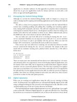
The show interfaces ethernet [interface number ] command
enables you to view statistics related to a particular Ethernet inter-
face. Figure 18.3 shows the results of this command on an Ethernet
0 interface on a Cisco 2505 router.
PART IV Ad vanced Confi guration and Confi gurati on To o l s
CHAPTER 18 Basi c Router Tr o u b l e s h o o t i n g
FIGURE 18.3
The show
interfaces
ethernet command
can be used to view sta-
tistics related to the
Ethernet interfaces
installed on the router.
Although the statistics provided might seem rather cryptic at first
examination, they actually provide a great deal of information that
can help you troubleshoot problems related to an Ethernet interface.
Some of these statistics also provide insight into the use of other
hardware resources on the router such as RAM. The list that follows
highlights some of the statistics found in response to the show
interfaces ethernet [interface number] command.
■ Ethernet 0 is Up, Line Protocol is Up—This lets you know that
the interface is active and that the Ethernet protocols believe
that the line is usable. If the interface is down, check the LAN
connection to the interface. You can also try to bring up the
interface in the Configuration mode (if the LAN connection is
okay). Enter the configuration-if mode for the interface and
“bounce” the interface. Use the shut command (to down the
interface), and then use the no shut command to up the inter-
face. This might bring the interface back up.
■ Hardware Address—This is the hexadecimal MAC address for
the interface.
■ Internet Address—This is the IP address and subnet mask
assigned to the interface (you will learn IP addressing in the
“Troubleshooting TCP/IP” section).
3 0 9
PART IV
Troubleshoo ting LAN Interfaces CHAPTER 18
■ MTU—This is the maximum transmission unit for the interface
in bytes.
■ BW—This is the bandwidth for the interface in kilobits/second.
■ Rely—This is a measurement of the reliability of the line with
255/255 being 100 percent reliable. The lower the first number
in the reliability measurement, the less reliable the interface con-
nection (due to downed lines or other problems).
■ Load—This measures the current load on the interface. The
measurement 255/255 would be a totally saturated interface
(meaning too much traffic, you might need to add another inter-
face or router to service the network).
■ Encapsulation—This is the Ethernet frame type assigned to the
interface. ARPA is the default and is the 802.2 Ethernet frame
type. If the frame type doesn’t match the frame type used on
your network (such as an older NetWare network using 802.3
raw frames, you must reset the frame type. Use the arp com-
mand at the config-if prompt for the interface and assign the
correct Ethernet encapsulation type (such as arpa, or snap).
■ Collisions—This shows the number of collisions monitored by
the interface. A large number of collisions means that there
might be some physical problem on the network such as a break
in a cable or a malfunctioning network interface card that is gen-
erating a large amount of broadcast traffic. This could also mean
that cables are too long on the LAN.
As you can see, this one IOS command provides a lot of information
related to the health of a particular interface and the traffic that it is
experiencing. And as you also can see, problems with an Ethernet
interface might be core problems with the LAN that it is servicing
(such as excessive collisions).
Troubleshooting Token Ring with Show
Token Ring uses token passing as its method of access to the LAN.
The device with the token can transmit. Other devices must wait
until they take possession of the token so that they can transmit. So
problems with Token Ring networks don’t revolve around packet
collision issues as Ethernet does.
3 1 0
The command to view the statistics related to a Token Ring interface
is show interfaces tokenring [interface number]. And as with the
show interfaces command on Ethernet interfaces, this command
shows the status of the interface and information on the hardware
and protocol addresses of the interface as well as information on the
interface’s reliability. A number of the parameters shown in the sta-
tistics are the same as those shown for an Ethernet port (such as
Hardware Address, Internet Address, MTU, BW, and Rely). Other
settings have to do with Token Ring LAN functionality such as ring
speed.
■ Token Ring is Up—This lets you know that the interface is cur-
rently active. If the interface is down, you can try to bounce the
interface in the configuration-if mode to get it back online.
■ Hardware Address—This is the hexadecimal MAC address for
the interface.
■ Internet Address—This is the IP address and subnet mask
assigned to the interface (you will learn IP addressing in the
“Troubleshooting TCP/IP” section).
■ MTU—This is the maximum transmission unit for the interface
in bytes.
■ BW—This is the bandwidth for the interface in kilobits/second.
■ Rely—This is a measurement of the reliability of the line with
255/255 being 100 percent reliable. This measurement is aver-
aged for the interface over a period of five minutes.
■ Load—This measures the current load on the interface. The
measurement 255/255 would be a totally saturated interface and
again means that you might have too large of a Token Ring
LAN being serviced by the one interface on the router.
■ Ring Speed—This is setting for the speed of the Token Ring
LAN that the router is connected to. All devices on the Token
Ring network, including the router, must be using the same ring
speed (either 4Mbps or 16Mbps). Any mismatches will result in
an interruption in the flow of data. To check the ring speed set
on the router use the show running-config command. If you
need to reset the ring speed enter the config-if mode on the
router console for the interface. Then use the ring-speed com-
mand to reset the ring speed.
PART IV Ad vanced Confi guration and Con fi guration To o l s
CHAPTER 18 Basi c Router Tr o u b l e s h o o t i n g
3 1 1
PART IV
Tro ublesh ooting WA N In te rfaces CHAPTER 18
■ Restarts—On Token Ring Interfaces this value should always be
0. If it is other than 0, the interface has been restarted because of
some problem on the Token Ring LAN.
Troubleshooting Token Ring interfaces on routers requires a very
good understanding of how Token Ring LANs operate. Problems
such as congested rings, for example, require that you further seg-
ment the Token Ring LAN. And although this section provides some
primer information on Token Ring interface settings, you should
learn a lot more about Token Ring itself than can be provided in this
book. A very good source for Token Ring related information is
www.ibm.com. They are the architects of Token Ring and provide a
number of white papers and other resources related to Token Ring
LANs.
Troubleshooting WAN Interfaces
Basic troubleshooting of WAN interfaces is very similar to trou-
bleshooting LAN interfaces. You can use the show interface serial
[interface number] to view the statistics related to a particular inter-
face. However, more precise troubleshooting of WAN interfaces is
much more complex than LAN interfaces because of the different
WAN protocols (such as PPP or Frame Relay) that you might be
using on your serial connection between routers. Also thrown into
this mix is the state of your service provider’s leased lines or packet
switched network connections.
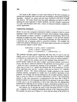
Let’s take a look at the show interface serial command and how some
of the statistics related to a serial interface can provide insight into
potential problems. Figure 18.4 shows the results of the show inter-
face serial 0 command on a 2505 router.
■ Serial 0 is Up—This lets you know that the interface is active. If
the interface is down, there might be a problem with the con-
nection from the router to the CSU/DSU. Check the cable. Or
there might be a problem with the telephone company line that
you are connected to (if the CSU/DSU is okay, call your service
provider to see if the line is down—first check the status of the
3 1 2
router on the other end of the connection). You can also try to
bounce the interface to bring it back up (as discussed in the
Ethernet section).
PART IV Ad vanced Confi guration and Confi gurati on To o l s
CHAPTER 18 Basi c Router Tr o u b l e s h o o t i n g
FIGURE 18.4
The show
interfaces serial
command can be used to
view statistics for a ser -
ial interface on a router.
■ Line Protocol is Up—This lets you know that the WAN proto-
cols in use believe that the line is usable. If the line protocol is
down, your router might not be configured correctly (use the
show running-config command to check this). Or the router that
you are attempting to connect to isn’t configured with the
appropriate protocol (check it too). You might also be experienc-
ing a problem due to the service provider’s line or switching
equipment.
■ Internet Address—This is the IP address and subnet mask
assigned to the interface (you will learn IP addressing in the
“Troubleshooting TCP/IP” section).
■ MTU—This is the maximum transmission unit for the interface
in bytes.
■ BW—This is the bandwidth for the interface in kilobits/second.
This is set for the interface at the config-if prompt using the
bandwidth command. The bandwidth must be set to a value that
coincides with the speed of the line that the router’s serial inter-
face is connected to.
Check the CSU/DSU
signal
You can use a monitoring
device called a breakout
box to determine whether
you are getting a signal
from the CSU/DSU.
Disconnect the CSU/
DSU from the router and
connect it to the breakout
box. If you don’t get a
signal, the leased line
might not be connected to
the CSU/DSU or the line is
down.
3 1 3
PART IV
Troublesh ooting TCP /I P CHAPTER 18
■ Rely—This is a measurement of the reliability of the line with
255/255 being 100 percent reliable. The lower the first number
in the reliability measurement the less reliable the interface con-
nection (due to downed lines or other problems).
■ Load—This measures the current load on the interface. The
measurement 255/255 would be a totally saturated interface
(meaning too much traffic, you might need to add another inter-
face or router to service the LAN).
■ Encapsulation—This is the WAN protocol assigned to the inter-
face. It must match the WAN protocol on the router that is at
the other end of the connection. The WAN protocol must also
be set for the type of service you are being provided from your
service provider (don’t set it for PPP if you are connecting to a
Frame-Relay switch).
■ CRC—This shows the number of cyclical redundancy checks
that have failed on incoming packets. This is usually an indica-
tion that the line provided by the phone company is experienc-
ing a great deal of noise or that your serial cable from the router
to the CSU/DSU is too long.
Again, this is only an overview of the information provided by the
show command for a serial interface on a router and how it relates to
potential problems. Troubleshooting WAN connection demands that
you have a great deal of experience configuring and working with
WAN connections on an internetwork. For example, troubleshooting
dial-up connections and ISDN connections are really a science unto
themselves. As with any discipline, the more time you spend working
with WAN issues on internetworks the better you become at diag-
nosing problems relating to them.
Troubleshooting TCP/IP
TCP/IP is a large routable protocol stack that can present a number
of interesting problems to router administrators. You’ve already seen
in Chapter 10 that subnetting IP networks can be a mathematical
nightmare in and of itself. And you will find that when you work
with IP networks, a number of the problems that you face have to do
with improper configurations on a router or node on the network.
Routers configured as a
DCE must provide a
clock rate
If you have configured your
router as a DCE, the router
must provide a clock rate
for the serial connection.
At the config-if prompt for
the interface, use the
clock rate command
to set the appropriate clock
rate. Legal clock rates
range from 1200 to
800,000,000 bits per sec-
ond. To see if an interface
has been configured as a
DCE, run the show
controllers
serial [interface
number] command. This
will show you the clock
rate set for the line and the
type of cable connected to
the interface (DCE or DTE).
3 1 4
A duplicated IP address on a workstation will take that workstation
offline and the workstation that also has been configured with the
duplicate IP address.
Let’s take a look at some of the common IP network–related prob-
lems first. Then you will look at the ping and trace commands and
how you can use them to help troubleshoot IP–related problems.
The list that follows provides some basic IP related problems and
how you would fix them:
■ Default Gateway Improperly Configured—When you set up the
workstations and servers on a LAN that connects to a router, the
default gateway for the LAN (and all the computers on it) is the
IP address of the router interface directly connected to the
LAN. If a workstation cannot communicate with the network,
check the default gateway (or even more basic—check the IP
address).
■ Routing Not Enabled On One of the Routers—Use the show ip
route command to see whether the router has been enabled for
routing. If the routing table doesn’t have any learned entries in
it, the router has not been enabled for routing.
■ Routing Protocol Has Not Been Enabled—You must enable a
routing protocol, if you want the router to build a routing table.
Use the show running-config command to see whether a routing
protocol has been enabled (which should match the routing pro-
tocol you are using on the other routers on your network).
■ No IP Address Configured on an Interface—You will have prob-
lems if the router interface has not been configured with an IP
address. Use the show ip interfaces command to make sure
your interfaces have been configured with an IP address (except
in the cases of serial connections which can be configured IP
unnumbered).
Using ping
A great tool for checking the physical network connection between
two routers on the internetwork (or any two nodes) is the ping com-
mand. ping sends an ICMP echo packet to the noted IP address and
if the address received the packet it echoes the packet back to the
PART IV Ad vanced Confi guration and Confi gurati on To o l s
CHAPTER 18 Basi c Router Tr o u b l e s h o o t i n g
Watch those Access
lists
I discussed standard IP
Accesslists in Chapter 14,
“Routing AppleTalk.”
Grouping Access lists to
router interfaces without a
good understanding on how
those lists will affect net -
work traffic is a big mis-
take. Don’t use Access
Control lists unless you are
sure that it will filter traffic
that you don’t want, not
traffic that you require to
be passed through the
routerinterface.
3 1 5
PART IV
Troublesh ooting TCP/I P CHAPTER 18
source. The time that the echo packet takes to go the roundtrip is
measured in milliseconds.
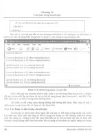
To use the ping command, type ping [ip address], where you supply
the IP address of the destination router interface or node on the net-
work. Figure 18.5 shows the results of a ping command between two
routers.
FIGURE 18.5
The show ping com-
mand can be used to
check the connection
between a router and
othernodes on the inter-
network.
An extended ping command also exists that enables you to set the
protocol type for the echo packet (ping can be used with IPX and
AppleTalk), the size of the packet, and the timeout for the response.
Type ping and then press Enter. Supply the information requested
by each step in the extended ping command, followed by Enter, (just
press Enter to accept the defaults). Figure 18.6 shows the results of
an extended ping command.
FIGURE 18.6
The extended ping
command enables you to
set parameters such as
protocol type and time-
out for the ping packet.
Using trace
Another command that you can use to troubleshoot connectivity
problems is the trace command. It enables you to see the route that
the packets take from source to destination. This enables you to
determine if routers that would normally participate in the path
between a particular router and node or router and router is cur-
rently down. To use the trace command, type trace [ip address].
Using ping and trace
ping and trace can
both beused at the user
prompt or the privileged
prompt.
3 1 6
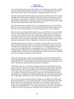
The results of the trace command shown in Figure 18.7 show that
the route determined by trace consisted of one directly connected
router with the IP address of 130.10.64.2. The trace took four mil-
liseconds.
PART IV Ad vanced Confi guration and Confi gurati on To o l s
CHAPTER 18 Basi c Router Tr o u b l e s h o o t i n g
FIGURE 18.7
The trace command
can show the route
between two routers on
the internetwork.
Troubleshooting IPX
Networking with IPX poses some of the same problems that you
face when working with IP. Incorrectly entered IPX network num-
bers on router interfaces can cause problems just as incorrectly con-
figured IP addresses on interfaces do. Let’s take a look at some of the
basic troubleshooting issues you might face when working with IPX
networks:
■ Incorrectly Configured Clients—Novell Networks are very
server-centric and so the hosts on the network must have their
client software configured to correctly communicate with the
NetWare server. It is the server that verifies the user to the net-
work, so make sure that you are using the appropriate version of
the client software for the version of server software that you are
using.
■ Too Many Clients—When you install a NetWare server you
must provide a disk that shows the server how many licenses you
have purchased for client machines. If you try to add more
clients than you have licenses for, the server will not let the user
on the network. Use the Load Monitor command on the
NetWare server to check the number of client spots available on
the server.
■ Problems with Ethernet Encapsulation—NetWare supports sev-
eral different Ethernet frame types—such as Ethernet 802.2 and
Ethernet 802.3 (raw Ethernet) If you inadvertently mismatch the
frame type on a router LAN interface with the frame type used
3 1 7
PART IV
Tro ublesh ooting Apple Ta l k CHAPTER 18
by NetWare hosts and servers, the router is going to have prob-
lems routing packets. Check the frame type (encapsulation) of all
your router interfaces using the show ipx interface brief com-
mand (the results of this command on a 2505 router appear in
Figure 18.8).
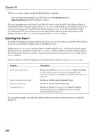
FIGURE 18.8
Quickly check the
Encapsulation type of
IPX-enabled interfaces
on the router.
Obviously, one of the first things that you should do when you expe-
rience problems on a router is check your configuration and the set-
tings on the interfaces. Other troubleshooting issues revolve around
hardware and cabling issues. Because IPX is typically found on
LANs, make sure that the LAN is working correctly before connect-
ing to the router. Then if you have problems you know that they are
on the router not the network.
SEE ALSO
➤ For a review of IPX addressing,see page 214.
Troubleshooting AppleTalk
AppleTalk LANs are typically small (when compared to corporate IP
or IPX networks); it is somewhat simpler to deal with physical
cabling problems and hardware problems (because you are typically
dealing with fewer computers). Dealing with configuration and soft-
ware problems is another issue.
When Apple Macintosh users looks for a particular service on the
AppleTalk network, they employ the Chooser on the Macintosh. If
the user can’t find a particular service or zone, you’ve got a problem.
And you will find that most of the problems with AppleTalk networks
typically revolve around cable ranges and zone names. If a router’s
configuration doesn’t agree with the cable ranges and zone names
used on the AppleTalk internetwork that it is connected to, routing
problems will occur and Mac clients won’t find what they’re looking
for in the computer’s Chooser.
Using extended ping
You can use extended
ping tocheck nodes on
the network (or router
interfaces) using their IPX
address in the form
network number.node
number.
3 1 8
Another thing to keep in mind, because the administrator assigns
cable ranges, is that you don’t want to inadvertently configure two
LAN segments with the same network number or cable range. This
will obviously cause routing problems.
Two router commands that are useful for troubleshooting in
AppleTalk environments are ping and the debug appletalk routing
command. ping, as you know, enables you to check the connection to
a particular node on the network or check whether or not a router
interface is up. The debug command enables you to view advertise-
ments of routes on the AppleTalk internetwork and reports of con-
flicting network numbers on the network.
To use the ping command for AppleTalk addresses, type ping
appletalk [network number.node address ]. For example, on my
router I want to ping the Ethernet 0 port on another router that has
been configured for AppleTalk. The command is ping appletalk
12.176 (you can also use the extended ping command for AppleTalk).
Figure 18.9 shows the result of this command.
PART IV Ad vanced Confi guration a nd Confi gurati on To o l s
CHAPTER 18 Basi c Router Tr o u b l e s h o o t i n g
AppleTalk phases
AppleTalk actually exists in
two different phases: 1 and
2. Phase 1 didn’t allow
cable ranges but required a
single network address for
a network segment. If you
are trying to route traffic
through an AppleTalk inter-
network where both
AppleTalk Phase 1 and
Phase 2 are in use, you
might experience routing
problems. It is a good idea
to upgrade routers and
other devices to support
AppleTalkPhase 2.
FIGURE 18.9
Check the status of a
node on the AppleTalk
network using the ping
command.
The debug command (a Privileged command) is simple to use, but it
requires a lot of the router’s resources, such as memory, so you don’t
want to leave it on forever (use no debug all, to quickly turn it off).
The command is entered as debug apple routing. Figure 18.10 shows
some of the information that the command provides.
A Final Word on Troubleshooting
In this chapter you have taken a look at some of the basic trou-
bleshooting techniques for hardware, network architectures (such as
Ethernet), and network protocols (such as IP). One thing that I
haven’t talked about is a network map. Any network administrator
worth his salt will be sure to have an up-to-date map of the entire
network including the addressing scheme and the location of devices
such as routers, bridges, and servers.
3 1 9
PART IV
A Final Word on Tr o u b l e s h o o t i n g CHAPTER 18
A map (or diagram if you want) of your internetwork can be used to
find node addresses when you need them for commands like Ping or
Telnet. The map also provides you with a complete overview of the
topology of the network. You really can’t run the network efficiently
without a map.
And creating a network map is easy. Network diagramming tools
such as Visio Standard (from Visio Corporation) make it easy to
build simple and complex network diagrams. Other versions of Visio
such as the Enterprise version supply all the icons that you need for
just about every networking device manufactured, enabling you to
create diagrams that can be understood by any network administra-
tor.
Even if you don’t use a network-diagramming tool, use some sort of
graphics package and get a network map on to your computer, so
that you can upgrade it as the network topology changes or grows.
You won’t be sorry that you have it when trouble rears its ugly head.
Good luck!
FIGURE 18.10
Use debug to monitor
AppleTalk routing
updates.
A P P E N D I X E S
V
Basic Command Summary 323 A
Selected Cisco Router
Specifications 337 B
Glossary 343
p a r t
S u m m a r y
Router Examination Commands
•
Router Memory Commands
•
Password and Router Name
•
Configuration Commands
Interface Configuration Commands
•
IP-Related Commands
•
IPX-Related Commands
•
AppleTalk-Related Commands
•
WAN-Related Commands
•
Troubleshooting Commands
•
Miscellaneous Commands
•
A
A p p e n d i x
P R A C T I C A L
3 2 4
Cisco IOS Command Summary
This appendix provides a summary of the Cisco IOS commands cov-
ered in this book. The commands are broken down into tables; each
table contains a list of associated commands. Commands in each
table are listed alphabetically. For example, router examination com-
mands are contained in Table A.1. This resource is best used after
you have completed reading the entire book. You will then under-
stand the context of each command and its use.
Because some root commands overlap—for example, show is used as a
general examination command and as a troubleshooting command—
you might find variations of the same command in more than one
table. The fact that commands are grouped by their typical usage,
however, should make the tables an easy way to reference a particular
group of related commands.
For example, you can go to a particular table category, such as IP-
related commands or AppleTalk-related commands, and find the spe-
cific IP or AppleTalk IOS command you are looking for. It is
understood that each command is executed by typing the command
at the appropriate prompt (noted in the results of the command) and
then pressing Enter.
Router Examination Commands
Router examination commands enable you to quickly check the sta-
tus of the router’s interfaces and other parameters. Table A.1 summa-
rizes these commands. These commands can be used at both the user
and privileged prompts unless otherwise noted.
Table A.1 Router Examination Commands
Command Results
show CDP Neighbor Shows the routers that are directly connected to
your router by LAN or serial connections.
show clock Shows the time and date settings for the router.
show flash Shows the IOS file or files contained in the
router’s Flash RAM and the amount of total
Flash RAM and used Flash RAM.
PART V A p p e n d i x e s
APPENDIX A Basi c Command Sum mary
3 2 5
PART V
Cisco IOS Command Su mmary APPENDIX A
show history Shows a list of your last 10 commands.
show hub Shows information on the status of the hub ports
of a 2505 router.
show interface ethernet Shows the current configuration of a specified
[interface number] Ethernet interface.
show interface serial Shows the current configuration of a specified
[interface number] serial interface.
show interfaces Lists all the interfaces on the router and statistics
related to the interface such as their current con-
figuration and encapsulation. Also tells you if the
interface is active.
show processes Shows CPU utilization information.
show protocol Lists the routing protocols configured on the
router.
show version Shows the version of the IOS currently running
on the router.
Router Memory Commands
Router memory commands enable you to check information such as
the current running configuration or the startup-configuration
stored in NVRAM. These commands also enable you to copy or
erase configuration files from the router’s memory. Commands for
saving and retrieving router configurations or IOS files to and from
an FTP server are also included in this list. These commands can be
used at the user and privileged prompt unless otherwise noted (see
Table A.2).
Table A.2 Router Memory–Related Commands
Command Results
copy flash tftp Privileged command to copy an IOS
file from Flash to the TFTP server
copy running-config startup-config Copies the currently running
configuration to the router’s NVRAM.
Command Results
continues…
3 2 6
copy startup-config tftp Privileged command to copy the
startup configuration from NVRAM to
a TFTP server.
copy tftp flash Privileged command to copy an IOS
file from a TFTP server to the router’s
Flash RAM.
copy tftp startup-config Privileged command to copy a startup
configuration file from a TFTP server
to the router’s NVRAM.
erase startup-config Erases the startup-configuration from
the router’s NVRAM.
show running-config Privileged command that shows the
router configuration currently running
in RAM.
show startup-config Privileged command that shows the
router configuration stored in the
router’s NVRAM. Loaded by the
router when the router is rebooted.
Password and Router Name Configuration Commands
Password and router name commands enable you to change the vari-
ous passwords on the router including the router login password and
the secret enable password for the Privileged mode (see Table A.3).
This list also contains the command for changing the router’s name.
Each of these commands is used in the Configuration mode.
Table A.3 Password and Router Name Commands
Command Results
enable secret password [password] Global configuration command that
enables you to change the secret
Privileged mode password on the
router.
hostname [name] Global configuration command that
changes the name of the router.
PART V A p p e n d i x e s
APPENDIX A Basi c Comm and Summary
Table A.2 Continued
Command Results
3 2 7
PART V
Cisco IOS Command Su mmary APPENDIX A
line console 0 Enables you to enter the Line
Configuration mode to set the login
password for the router.
line vty 0 4 Enables you to enter the virtual
terminal Configuration mode to set
the virtual terminal password for the
router.
password [password] Used in the line console 0
Configuration mode to set the login
password for the router; also used in
the line vty 0 4 Configuration mode to
set the virtual terminal password for
the router.
SEE ALSO
➤ For help recovering forgotten passwords,see page 137.
Interface Configuration Commands
Interface configuration commands relate to configuring interfaces on
the router (see Table A.4). The general configuration command, con-
fig (the Privileged command to enter the configuration mode), is
included among the commands. For interface configuration related
to a specific network or WAN protocol, see the appropriate table
(such as WAN-Related Commands).
Table A.4 Interface Configuration Commands
Command Results
config Privileged command that enables you to enter
the Global Configuration mode.
Ctrl+Z While not an actual interface configuration com-
mand, it is the command used to end a router
configuration session.
enable cdp Enables a particular interface (you must be in the
config-if Configuration mode) to show con-
nected neighbor routers (you can then use the
show cdp neighbor command on the router).
Command Results
continues…
3 2 8
encapsulation Interface–specific configuration command that
[encapsulation type] enables you to set the encapsulation type for a
LAN or serial interface on the router.
interface ethernet Global Configuration command that enables you
[interface number ] to configure parameters related to a particular
Ethernet interface.
interface serial Global configuration command that enables you
[interface number] to configure parameters related to a particular
serial interface.
IP-Related Commands
IP commands are related to configuring IP addressing on interfaces
and enabling IP routing on the router (see Table A.5). Commands
related to RIP and IGRP are also included.
Table A.5 IP-Related Commands
Command Results
access-list [list #] permit Global configuration command
or deny [ ip address] for creating an IP Access list.
[wildcard mask] The network or node address that
will be permitted or denied must be
included and the wildcard mask must
be provided. Repeat this command
for each line that will appear in
the Access list. The list # range
for IP lists is 1–99.
debug ip igrp transaction Privileged command that enables you to
view statistics related to IGRP update
messages on the router.
debug ip rip Privileged command that enables you to
view the RIP update messages sent and
received by the router.
PART V A p p e n d i x e s
APPENDIX A Basi c Comm and Summary
Table A.4 Continued
Command Results