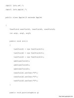
ccna practical cisco routers phần 7 docx
Bạn đang xem bản rút gọn của tài liệu. Xem và tải ngay bản đầy đủ của tài liệu tại đây (4.39 MB, 39 trang )
Routing AppleTa l k
Understanding AppleTalk
•
Configuring AppleTalk Routing
•
Monitoring AppleTalk routing
•
c h a p t e r
13
2 2 8
Understanding AppleTalk
AppleTalk is a routable network protocol stack that provides network
connectivity for peer computers (typically Apple Macintosh comput-
ers) that want to share files and other network resources such as
printers. AppleTalk has its own strategy for network addressing and
the grouping of computers into logical workgroups, called zones.
Because there always seems to be at least a few Apple computers at
every company or institution for multimedia and desktop publishing
tasks, it makes sense to be able to route AppleTalk on a Cisco router
and allow these computers to share information over an i n t e r n e t w o r k .
Macintosh computers come equipped with a built-in network inter-
face that can be attached to a hub or other connectivity device using
an Apple shielded twisted-pair cable (You have been able to network
Macs since they arrived on the scene. The new PowerMacs and G3
computers ship with built-in Ethernet ports). Macintoshes that are
integrated into other network architectures can be outfitted with an
additional network interface card for that particular architecture
(such as an EtherTalk card). AppleTalk supports Ethernet
(EtherTalk), Token Ring (TokenTalk), and FDDI (FDDITalk).
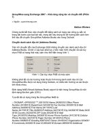
Figure 13.1 shows the protocols in the AppleTalk stack that reside at
the lower levels of the OSI model. These protocols are used by com-
puters and routers on the internetwork to exchange information such
as the location of resources (a server or printer) These protocols are
discussed in the following list:
• DDP (Datagram Delivery Protocol)—A Network layer protocol
that provides a connectionless datagram delivery system similar
to UDP in the TCP/IP stack.
• AARP (AppleTalk Address Resolution Protocol)—A Network layer
protocol that resolves AppleTalk network addresses with hard-
ware addresses. AARP sends broadcasts to all stations on the net-
work to match hardware addresses to logical destination
addresses for packets.
• ZIP (Zone Information Protocol)—A Network and Transport layer
protocol that is used to assign logical network addresses to nodes
on the network. This protocol is discussed in more detail in the
next section.
PART III Routing LAN Protocols
CHAPTER 13 Routing App leTa l k
2 2 9
PART III
Understandin g AppleTa l k CHAPTER 13
• RTMP (Routing Table Maintenance Protocol)—A Transport layer
protocol that is responsible for establishing and maintaining
routing tables on routers that are enabled to route AppleTalk.
Routers periodically broadcast routing table information to
neighboring routers providing the hops to and the location of
AppleTalk networks on the internetwork.
• NBP (Name Binding Protocol)—A Transport layer protocol that
maps lower layer addresses to AppleTalk names that identify a
particular network resource such as a printer server that is acces-
sible over the internetwork.
FIGURE 13.1
The routing-associated
protocols of the
AppleTalk stack mapped
to the OSI model.
SEE ALSO
➤ For general information on AppleTalk in relation to other networking architectures and a look
at the AppleTalk protocol stack,see page 49.
AppleTalk Addressing
AppleTalk uses a 24-bit addressing system that identifies the network
segment that the node exists on and the node address itself, which
identifies the actual workstation or server.
2 3 0
The network address is 16 bits long and the node address portion of
the AppleTalk address is 8 bits. Because the number of bits is always
fixed for network and node address, you cannot subnet AppleTalk
networks as you can with IP addressing. Written in dotted decimal
format, the AppleTalk address for particular node would take the for-
mat: network.node.
Network addresses are assigned to the various AppleTalk networks
by the network administrator and can be a single number designating
one network on the network wire or it can be a range of network
numbers specifying a number of networks on the same wire. For
example, a network address designated as 10-10 means that only one
network (network 10) exists on the physical wire that the computers,
various hubs, and printers are connected to. A range such as 100-130
would designate multiple networks inhabiting the same network
wire. This would be referred to as a cable range.
When multiple network numbers inhabit the same AppleTalk net-
work segment this segment is called an extended segment. Those with
only one network number are called nonextended. Each extended net-
work segment can have 253 node numbers associated with each of
the network numbers assigned to that particular physical network.
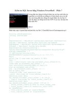
Figure 13.2 shows an AppleTalk internetwork with a large LAN
made up of extended segments and a LAN that is a nonextended seg-
ment. The fact that multiple network addresses can be assigned to
the segment (with each network number limited to 253 nodes) makes
it possible to put a large number of nodes on any one network seg-
ment. Remember that the 8-bit node address limits the number of
nodes available, so increasing the number of network addresses avail-
able on the network segment increases the number of nodes you can
place on it.
AppleTalk node addresses are very easy for the network administra-
tor to deal with because they are dynamically assigned. When a
Macintosh comes online with the network, the computer will send
out a ZIP broadcast to determine the network number or range of
network numbers available on the wire. It will also generate a ran-
dom node number. The node determines whether the node number
is already in use by issuing an AARP broadcast.
PART III Routing LA N Protocols
CHAPTER 13 Routing App leTa l k
AppleTalk phase 1 ver-
sus AppleTalk phase 2
There have actually been
two different phases of
AppleTalk: 1 and 2.
AppleTalk phase 1 limited
the assignment of network
numbers to a physical net-
work segment to one net -
work number per physical
network. The number of
nodes on that network was
limited to 127, and the
number of servers was lim-
ited to 127, making the
total number of possible
computers 254. AppleTalk
phase 2 supplies you with
the ability to assign multi-
ple network numbers to the
physical network wire and
place an unlimited number
of nodes and servers on
that wire. Phase 2 also
allows multiple zones per
network. Our discussion of
AppleTalk in this chapter
will assume the use of
AppleTalk phase 2 (which is
the appropriate addressing
scheme for properly config-
uring Cisco routersfor the
routing of AppleTalk).
Dynamic addressing
versus static addressing
As already noted,
Macintosh computers
dynamically generate a net-
work node number on the
network. In stark contrast
is Novell NetWare (running
IPX/SPX) where the node
address is assigned stati-
cally using the computer’s
MAC hardware address.
2 3 1
PART III
Understandin g AppleTa l k CHAPTER 13
FIGURE 13.2
Extended AppleTalkseg-
ments connected by a
router.
If the chosen node address on the network number is already taken,
the computer will generate another random node address and send
out a new AARP broadcast. If the computer finds that all the node
numbers are used up on a particular network number, it will choose a
new network number and then continue to attempt to take posses-
sion of random node addresses on that network (in cases where
extended segments have been configured).
After the computer finds a network number and an appropriate node
number combination that is available, it will use that address (net-
work.node) as its permanent network address. For example, a com-
puter on network 10 that takes possession of node number 200
would have the permanent address of 10.200.
2 3 2
SEE ALSO
➤ For information on IP subnetting,see page 180.
AppleTalk Zones
Another network management tool provided by AppleTalk is the
ability to divide the AppleTalk network into zones. Zones are logical
groupings of users, similar to the concept of workgroups in
Microsoft peer-to-peer networking. For example, you may have your
desktop publishing staff spread throughout your building; let’s say
you have Mac users in the Marketing department, some in the
Publications department, and so on. You can group these desktop
publishers into a logical networking group (known as a logical zone)
even though they are attached to different segments of the physical
AppleTalk network.
Grouping all the desktop publishing staff into the logical zone “desk-
top” allows these groups to advertise for and access printing and
other network services that are spread throughout the building.
Routers enabled for AppleTalk will actually build zone tables that can
forward broadcast messages from segment to segment on the net-
work, if they are part of the same logical zone.
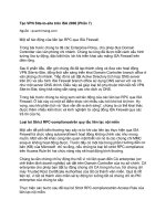
Zone names are flexible and contain alphanumeric and numeric
characters. Marketing1 would be a legal zone name as would
destkopA1. Figure 13.3 illustrates the concept of combining
AppleTalk LAN segments into the same zone.
Configuring AppleTalk Routing
When you enable AppleTalk on your routers and then appropriately
configure the router interfaces, the routers will build routing tables
that contain network path information much like IP networks. These
routing tables allow routers on the internetwork to forward packets
on to the appropriate router as the packets move from the sending
node to the receiving node.
Before you can configure the router interfaces for AppleTalk routing,
you must use a global configuration command to turn AppleTalk
routing on.
PART III Routing LAN Protocols
CHAPTER 13 Routing AppleTa l k
Reserved node numbers
AppleTalk does reserve cer-
tain node numbers from the
pool of 255 numbers—0,
254, and 255. The node
number 0 isreserved for
temporary use by nodes
attempting to determine
which network they reside
on. Node numbers 254 and
255 are used in broadcast
messages to the network,
so they cannot be assigne
Learning more about
AppleTalk networking
AppleTalk isactually a very
sophisticated network pro-
tocol stack and as robust
and complex as TCP/IP or
IPX/SPX. Although you will
probably run into AppleTalk
less frequently than these
other two network protocol
stacks, it is still a very
viable protocol because
Apple computers are com-
mon in the desktop publish-
ing and multimedia realms.
Because this book is about
routers and how they work,
the coverage of AppleTalk
is limited to broad princi-
ples and its addressing sys-
tem in relation to routing.
For more general informa-
tion on AppleTalk, check
out Apple Computer’s arti-
cle library at
o.a
pple.com. Additional
documentation on
AppleTalk and the Cisco
IOS can be found at
www.cisco.com.
2 3 3
PART III
Configuring A ppleTalk R outing CHAPTER 13
Enabling AppleTalk Routing
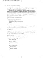
1. At the Privileged prompt type config t, and then press Enter.
2. Type appletalk routing, and then press Enter (see Figure 13.4).
3. To end the configuration session, press Ctrl+Z.
FIGURE 13.3
AppleTalk zones can be
used to “join” network
segments into one logi-
cal workgroup.
FIGURE 13.4
AppleTalk routing must
be enabled on the router
before interfaces can be
configured.
4. Press Enter to return to the Privileged prompt.
When you use the appletalk routing command, RTMP is configured
automatically as the AppleTalk routing protocol, so it doesn’t have to
be configured separately (as RIP and other IP routing protocols did).
2 3 4
Now that AppleTalk routing has been enabled, the interfaces that
will be involved in routing AppleTalk packets can be configured.
Both the cable range (the range of networks on each segment) and
the AppleTalk zones that will be used must be configured on each
interface. Figure 13.5 shows two different sites connected using
2505 routers.
PART III Routing LAN Protoco ls
CHAPTER 13 Routing AppleTa l k
FIGURE 13.5
Two AppleTalk LANS can
be connected using two
routers that are con-
nected via their serial
ports with a WAN proto-
col and some type of
leasedconnection.
Each LAN uses a cable range (providing a greater number of node
addressing possibilities) and the WAN connection uses one network
address (which much be configured on the serial port of each con-
nected router). For convenience, the WAN connection is also pro-
vided a zone name: WANCONNECT.
Table 13.1 summarizes the configuration information for the
AppleTalk network shown in Figure 13.5. We will use this configura-
tion information as examples when we configure the LAN and WAN
interfaces for AppleTalk in the next two sections of this chapter.
2 3 5
PART III
Configuring A ppleTalk R outing CHAPTER 13
Table 13.1 AppleTalk Network Configuration Information
Router Interface Cable Range Zone
Popeye Ethernet 0 1–10 Desktop
Serial 0 11 WANCONNECT
Olive Ethernet 0 12–20 Multimedia
Serial 0 11 WANCONNECT
Configuring LAN Interfaces
Configuring LAN interfaces for AppleTalk is very similar to config-
uring LAN interfaces for IP or IPX. Network and zone information
must be supplied in the Configuration mode for the interface you
want to configure.
Configuring a LAN interface for AppleTalk
1. At the privileged prompt type config t, and then press Enter.
You will be placed in the Global Configuration mode.
2. Type interface ethernet 0 (remember you can abbreviate your
commands), and then press Enter.
3. At the config-if prompt type appletalk cable-range 1-10, and
then press Enter. (Use the cable range you have determined for
your AppleTalk LAN.) This specifies the cable range for the
LAN that is connected to the LAN interface on the router.
4. To specify the zone for the interface, type appletalk zone desk-
top. Desktop is the name I am using as a sample LAN zone; you
would enter the name of your zone. Then press Enter (see
Figure 13.6).
FIGURE 13.6
LAN interfaces must be
configured with network
and zone information.
2 3 6
5. To end the configuration press Ctrl+Z.
6. Press Enter to return to the privileged prompt.
This procedure would be repeated for each LAN interface you want
to enable to support AppleTalk routing. Remember to provide the
correct network range and zone information for each interface.
Inadvertently using the same cable range twice would be similar to
using the same IP address on two different router interfaces; you
won’t get the routing that you expect between the networks.
Configuring WAN Interfaces
Configuring WAN interfaces is very straightforward. You must con-
figure the serial ports involved on each router for the appropriate
WAN protocol. You must also configure these interfaces with the
appropriate network and zone information. Two routers connected
via their serial interfaces will have the serial interfaces configured so
that they are on the same network and same zone (similar to IP
addressing, where both routers must have the connected serial inter-
faces on the same IP subnet).
Configuring a WAN interface for AppleTalk
1. At the privileged prompt type config t, and then press Enter.
You will be placed in the Global Configuration mode.
2. Type interface serial 0 (remember you can abbreviate your
commands), and then press Enter.
3. At the config-if prompt type appletalk cable-range 11. Use the
network number you have determined for your WAN connec-
tion. Then press Enter.
4. To specify the zone for the interface, type appletalk zone wan -
connect (wanconnect is used to provide a zone name for the serial
connection and also used as a reminder that this is a WAN
connection). Then press Enter (see Figure 13.7).
5. To end the configuration press Ctrl+Z.
6. Press Enter to return to the privileged prompt.
SEE ALSO
➤ For information on configuring a number of the commonly used WAN protocols on a Cisco
router, see page 259.
PART III Routing LAN Protoco ls
CHAPTER 13 Routing AppleTa l k
Configuring other LAN
t y p e s
The example given for
configuring AppleTalk on a
LAN interface uses an
Ethernet interface.
A p p l e Talk also supports
Token Ring and FDDI. So if
you were configuring a
Token Ring interface (the
first one on the router) for
the routing of AppleTa l k ,
you would supply the
network and zone informa-
tion for the Token Ring
0 interface.
2 3 7
PART III
Monitoring A ppleTalk R outin g CHAPTER 13
Monitoring AppleTalk Routing
After AppleTalk has been enabled on the router and the appropriate
router interfaces have been configured, you can view the AppleTalk
routing tables on a router and view the configuration of the various
interfaces. You can also view statistics related to the AppleTalk traffic
on the network including packets sent and received by the router.
To take a look at the routing table for a particular router, type show
appletalk route at the user or privileged prompt and then press
Enter. Figure 13.8 shows the routing table for a 2505 router that has
its Ethernet 0 interface connected to an AppleTalk LAN and a serial
connection to another 2505 router via its Serial 0 interface. The net-
work ranges marked with a C are directly connected to the router.
The network range (12–20) marked with an R is another AppleTalk
LAN reached via the serial connection to the other router (refer to
Figure 13.5 for a diagram showing how these AppleTalk networks
are connected).
FIGURE 13.7
WAN interfaces must be
configured with network
and zone information.
FIGURE 13.8
Use the show appletalk
route command to view
the AppleTalk routing
table on yourrouter.
Several show related commands are useful for monitoring the
AppleTalk setup on the router. You can view information related to a
particular interface or use a broader command that shows AppleTalk
configuration information for all enabled interfaces. You can also
view AppleTalk zones and their associated network ranges. Table
13.2 provides a summary of some of these commands. These com-
mands can be used at the user or privileged prompt.
2 3 8
Table 13.2 show appletalk Commands
Command Shows
Show appletalk interface brief Provides a short summary of all the
interfaces on the router and their
AppleTalk configurations
Show appletalk interface Provides more detailed information on
the router interfaces and their
AppleTalk configurations
Show appletalk interface e0 Enables you to view detailed
AppleTalk configuration information
for a specified router interface
Show appletalk zone Provides zone and network informa-
tion for the zone available on the
internetwork.
Show appletalk global Provides information on the number
of networks and zones available on the
internetwork and the time interval for
ZIP queries and RTMP updates.
Figure 13.9 shows the results of the show appletalk interface brief
command. Figure 13.10 shows the results of the show appletalk zone
command and Figure 13.11 provides a view of the results of the show
appletalk global command.
PART III Routing LAN Protocols
CHAPTER 13 Routing AppleTa l k
show commands pro-
vide a lot of information
If you’vebeen going
through the chapters in this
book in order, you probably
noticed that the show com-
mands listed in Table 13.2
are similar to show com-
mands that you used to
view information on a
router’s IP configuration
and IPX/SPX configuration
information. Learning sev-
eral of the different show
commands, enables you to
sit down at any router and
quickly get a good picture
of how that router has
been configuredfor any
network protocol.
FIGURE 13.9
Use the show
appletalk inter-
face brief command
to take a look at the
interface configurations
on the router.
2 3 9
PART III
Monitoring A ppleTalk R outin g CHAPTER 13
You can also turn on AppleTalk RTMP debugging and view the
RTMP routing updates sent and received by the router. Type debug
apple routing at the privileged prompt and press Enter. Figure
13.12 shows the results of this command. To turn off debugging,
type no debug apple routing, and then press Enter. Otherwise, you
will find it hard to enter any commands at the prompt.
FIGURE 13.10
Use the show
appletalk zone
command to take a look
at the zone and network
information onthe inter-
network.
FIGURE 13.11
Use the show
appletalk global
command to view the
overall AppleTalk config-
urationon the router.
FIGURE 13.12
The results of debug
apple routing.
2 4 0
As you can see, AppleTalk provides a routing environment every bit
as robust as IP or IPX. And in some ways AppleTalk provides fea-
tures, such as zones and extended networks, that enable you to easily
create complex internetworks of LAN computers at different loca-
tions. However, IP still rules the day (and IPX comes in second) so
your opportunity to implement AppleTalk routing in the workplace
may prove to be very limited.
PART III Routing LAN Protocols
CHAPTER 13 Routing AppleTa l k
A D VANCED CONFIGURAT I O N
AND CONFIGURATION TOOLS
IV
Filtering Router Traffic with
Access Lists 243 14
Configuring WAN Protocols 259 15
Configuring the Router with
Cisco ConfigMaker 271 16
Using a TFTP Server for Router
Configuration Storage 289 17
Basic Router Troubleshooting 301 18
p a r t
Access List
Understanding Access Lists
•
Working with IP Access Lists
•
Creating IPX Standard Access Lists
•
Creating AppleTalk Standard Access
•
Lists
14
c h a p t e r
2 4 4
Understanding Access Lists
So far in this book, you’ve had a chance to look at how three differ-
ent LAN protocols (TCP/IP, IPX/SPX, and AppleTalk) are config-
ured on a Cisco router. Interfaces have been configured and
connectivity issues relating to creating an internetwork that supports
these protocols have been discussed.
But whatyou’ve basically done is configure your routers so that the
doors to your internetwork are hanging wide open. Data packets and
broadcast packets have the run of your routers and can enter and
leave from any router port they want; you basically have configured a
Wild West boomtown without a sheriff. An important part of man-
aging routers and internetwork access is shutting the door on some
packets and being a little more selective about what interfaces and
routes are available to the data traffic from certain nodes and LANs
on your internetwork.
This is where an Access list comes in.
The Access list is a list of conditions called permit and deny statements
that help regulate traffic flow in to and out of a router (and can even
control user access to a router via Telnet). A permit statement basi-
cally means that packets meeting a certain conditional statement
won’t be filtered out. This means that these packets are “permitted”
to continue their journey across the interface. A deny statement (by
some criterion such as IP address or IPX network address) specifies
the packets to be filtered out, or discarded.
Access lists can be used to deny the flow of packets in to a particular
router interface or out of a particular router interface. They can also
be used to restrict the access capability of certain users and devices to
the routers on the internetwork.
How Access Lists Work
As already mentioned, Access lists are a series of conditional state-
ments that can restrict entry of packets from the internetwork to
your router based on particular criteria. Each statement in the Access
list is read in order, which means that packets coming into a particu-
lar router interface are compared to the list criteria from the top to
the bottom of the list.
PART IV Advanced Configuration and Configuration To o l s
CHAPTER 14 Filtering Router Traffic with Acc ess Lists
Access lists—a science
unto themselves
Working with Access lists
gives you a huge amount of
control overthe data flow
on your internetwork.
Understanding all the idio-
syncrasies of Access lists
is a huge task. This chapter
gets you started on this
subject and covers stan-
dard Access lists (you also
spend more time working
with IP Access lists
because IP is the most
routed protocol in the
world). Extended Access
lists can also be built for
network protocols such as
IP and IPX. For more infor-
mation, check out
www.cisco.com or
talk to your local Cisco
training group (training
information is also avail-
able on the Cisco Web
site). They provide hands-
on classesthat can help
you with a number of
advanced subjects related
to routers and the Cisco
IOS.
2 4 5
PART IV
Understanding Access Lists CHAPTER 14
Packets denied are dropped. Packets that are permitted are for-
warded as if no Access list existed. If a packet entering the router
doesn’t match the first statement in the Access list (which can be a
deny or permit statement) the packet is then compared to the next
statement in the list.
This process of matching the packet to the permit and deny state-
ments continues until the packet matches a criteria in the Access list
and is either forwarded or dropped. Figure 14.1 illustrates the
process of a packet being matched to the deny and permit statements
in an Access list.
FIGURE 14.1
Packets areeither for-
warded or dropped
based on the statements
in the Access list.
A packet that is forwarded from an incoming interface (based on the
Access list grouped to that interface) may then face another Access
list that is grouped to an outgoing interface on the same router. This
means packets can be filtered when received by an interface and then
filtered again as it is switched to the departure interface.
2 4 6
For example, you may have a case where you don’t want packets
entering a router, so you block those packets from entering a partic-
ular interface, such as an Ethernet interface that is connected to a
LAN. Or you may want to filter the packets as they depart the
router. You don’t want the packets to leave by a particular serial
interface that is connected to another router by a slow WAN con-
nection. You can then assign a filter to this interface, which won’t
allow packets (addressed in a particular way) to depart from that
interface.
Building an Access List
Any interface the router can be grouped to Access lists. But there
can only be one Access list associated with the interface for each net-
work protocol that the interface supports. For example, on a router’s
Ethernet 0 port (which is configured for IP and IPX) an Access list
grouped to the interface can exist that filters IP traffic and another
Access list can exist that filters IPX traffic. However, you could not
have two lists that filter IP traffic grouped to the same interface.
A real plus with Access lists is that you can associate a single Access
list to more than one interface on a router. So, for example, the same
list could be used by an Ethernet 0 interface and an Ethernet 1 inter-
face on the same router. And you specify whether the Access list is
set to filter incoming packets on the interface or outgoing packets. In
fact, the same Access list could be grouped to one interface where it
filters incoming packets and grouped to another interface on the
same router where it filters outgoing packets.
Building an Access list is fairly straightforward; you build the list and
then apply it to a particular interface on the router. Be advised, how-
ever, that the Access list must contain at least one functioning permit
statement.
The tricky part of building an Access list is that you have two condi-
tional statements: deny and permit. You have to determine how you
will use these statements to actually limit traffic on the router (with-
out permitting traffic you don’t want and restricting traffic you do
want).
PART IV Advanced Configuration and Configuration To o l s
CHAPTER 14 Filtering Router Traffic with Acc ess Lists
2 4 7
PART IV
Wo rking with IP Acces s Lists CHAPTER 14
For example, your strategy might be to use the permit statement to
allow access to the router for packets originating on certain LANs on
your network (by specifying a separate permit statement that points
out each network address that will be permitted). This means that
you have several permit statements in the Access list. You can then
place a deny statement at the end of the Access list that denies entry
to all other networks (which is done in different ways depending on
the type of traffic, such as IP packets, that you are filtering).
Or you can use the deny statement to deny entry to certain node or
network addresses and then place permit statements near the end of
the Access list that allow a number of different networks to move
their packets through the interface on your router. Whichever strat-
egy you use, you certainly can’t permit a particular network address
access to the router through an interface and then deny these same
addresses in a later statement. After they hit that permit statement
those packets are forwarded, so they are gone even before they are
compared to the deny statement.
Creating good Access lists is really a journey in the realm of logic,
where you must carefully craft deny and permit statements that for-
ward packets that you want to have routed and drop packets that you
don’t want routed. And each conditional statement in the Access list
must be built so that it doesn’t countermand another statement in
the list. You certainly don’t want the Access list to inadvertently deny
the forwarding of packets by your router, when your router is the
only path for these packets as they move to their final destination.
Let’s look at some specific network protocols and how basic Access
lists are created for each. This will help shed some light onto the
logic of Access lists.
Working with IP Access Lists
Standard IP Access lists examine the source IP address of packets
that are to be filtered on a particular router interface. You use the
source IP address as the match criteria for the various deny and per-
mit statements that you place in the Access list.
Access lists are a com-
bination of deny and
permit statements
You will find that Access
lists for interfaces on a
router that is part of a
fairly good size internet-
work will have to weave a
filtering web using both
deny and permit state-
ments. And after specific
nodes and networks have
been dealt with in the
Access list, a deny all
statement (using a wildcard
statement based on the
network protocol address-
ing system) is typically
placed at the very bottom
of the Access list. This
denies packets that don’t
meet any of the conditions
you have set in your deny
and permit statements.
2 4 8
When designing an Access list that will be used on an interface (such
as Ethernet 0 or Serial 1) you must also decide whether the Access
list controls the entry of packets on that interface or whether the
Access list controls the departure of packets from that interface
(which will be forwarded out onto the internetwork). Whether the
Access list is for incoming or outgoing packets will have to be speci-
fied when the Access list is grouped to the interface. Figure 14.2
shows an IP Access list. I will discuss the commands for creating an
Access list in the sections that follow.
PART IV Advanced Configuration and Co nfiguration To o l s
CHAPTER 14 Filtering Router Traffic with Acc ess Lists
IP extended access lists
Although our basic discus-
sion of Access lists will
examine the use of
Standard Access lists for
protocols such as IP, you
can further fine-tune your
network traffic with
extended Access lists. In
the case of IP, extended
Access lists enable you to
filter packets based on not
only the source IP address,
but also the destination
address of the packet and
particular IP protocols such
as UDP and ICMP.
FIGURE 14.2
An IP Access list that
permits packets from
one network and then
denies all others.
Let’s take a look at a simple internetwork and use the IP addresses
that it provides to create Access lists for some of the routers on the
internetwork. Figure 14.3 supplies the information that you will use
to create your Access lists.
First, to keep things simple, you will create an Access list for the
Serial 0 interface on Router A. You want the data sent from worksta-
tion 1A to nodes on the 130.10.0.0 network to be able to use the
leased line that connects Router A to Router C as a route. However,
you don’t want any of the other LANs such as the LAN (200.90.20.0)
serviced by router B to use this WAN connection as a possible route
(because router B is directly connected to router C). So your list will
permit packets from workstation A1 and deny all other packets (from
the other LANs).
The first step in the process is to create the Access list. The second
step in the process is to group the Access list to an interface.
However, before you actually create the list, you need to look at one
more conceptual item related to IP Access lists—wildcard masks.
SEE ALSO
➤ For a review of IP addressing,see page 174.
2 4 9
PART IV
Wo rking with IP Access Lists CHAPTER 14
IP Wildcard Masks
Because the IP addresses used by in basic IP Access lists can be refer-
ring to node addresses, subnet addresses, or major network
addresses, there must be some mechanism to let the router know
which bits in the source IP address of packets that it received should
be checked against the IP address provided in the Access list. For
example, if the major network address 200.90.20.0 is used in a deny
or permit statement, you want to make sure that the bits in the first
three octets are used by the router when it enforces the statement in
the Access list on packets that are being processed by one of its inter-
faces (the interface that the Access list has been grouped to).
You do this with a wildcard mask. Bits that you want to have checked
in an address must have a wildcard mask value of 0. Bits in the
address that you don’t want checked are assigned a wildcard mask bit
FIGURE 14.3
A simple internetwork
crying out for some
Access lists.
Wildcard masks are not
subnet masks
Don’t confuse wildcard
masks with subnet masks.
Wild card masks are only
used in Access lists and
their purpose is to let the
router know which bits it
needs to check in the
source IP address of pack-
ets to determine whether
they should be filtered by
the Access list.
2 5 0
value of 1. So, for your major network address 200.90.20.0, where
you want all the bits in the first, second, and third octets to be
checked by the router, the wildcard mask would be 0.0.0.255 (the
binary equivalent of these decimal values would be 00000000
00000000 00000000 11111111).
In the case of a node address (such as 190.10.45.5) where you want
all the bits in each octet checked against your entry in the Access list
(this would be checked on each packet processed by the interface),
you would use a wildcard mask of 0.0.0.0. This means “check all the
bits in each octet.”
As you can see, when you are working with major network addresses
and node addresses, coming up with the wildcard mask is easy. To do
this, you would use all zero bits—which equal a decimal value of 0—
for octets to be checked, and all 1s or a decimal value of 255 for
octets not to be checked. However, when you are dealing with net-
works that have been subnetted, and you want to permit or deny cer-
tain subnets and ignore others (from your range of subnets found on
your network), you must construct a mask that tells the router which
bits to check in the IP addresses of packets it must process. Let’s say
that you have subnetted your network (a Class B network) into six
subnets as shown in Table 14.1.
Table 14.1 IP Address Ranges for Six Subnets on 130.10.0.0
Subnet # Subnet Address
1 130.10.32.0
2 130.10.64.0
3 130.10.96.0
4 130.10.128.0
5 130.10.160.0
6 130.10.192.0
You want to create a deny statement that will deny packets from sub-
nets 1, 2, and 3 (a subnet range of 130.10.32.0 through 130.10.96.0).
This statement would read as deny 130.10.32.0 0.0.31.255 . The IP
address of the first subnet follows the deny statement, and the wild-
PART IV Advanced Configuration and Configuration To o l s
CHAPTER 14 Filtering Router Traffic with Access Lists
Wildcard mask key-
words
In the case of anode
address where you want all
the address bits checked
against the entry in the
Access list, you use a wild-
card mask of 0.0.0.0.
However, you can replace
this wildcard mask with the
keyword “host,” which pro-
vides the router with the
same mask bits as does the
wildcard mask of all zeros.
In cases where you want to
specify that a permit or
deny statement act on all
IP addresses not given in
other deny or permit
statements in the Access
list, you can use the key-
word “any.” This is useful if
you want a deny any
statement, which denies all
IP addresses except for
those placed in permit
statements in the Access
list.