ccna practical cisco routers phần 6 docx
Bạn đang xem bản rút gọn của tài liệu. Xem và tải ngay bản đầy đủ của tài liệu tại đây (4.4 MB, 39 trang )
1 8 7
PART III
Subn etting IP Addresses CHAPTER 10
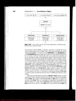
Now, you probably wonder where I came up with the 0 in the third
octet and the 1 in the fourth octet. The possible decimal values of
any octet range from 0 (where all bits are set to 0) to 255 (where all
bits are set to 1). So the first IP address in the subnet can have all 0s
in the third octet. So, why does the fourth position start with 1?
Remember, I said earlier that the node address could not be repre-
sented by octets containing all 0s or all 1s. If the fourth octet was 0,
both the node octets (the third and the fourth) would be all 0s, which
is used to denote the subnetwork address, and so it isn’t a legal
address for a node.
To determine the range of addresses for a particular subnet, you take
that subnet’s starting address and use all the addresses that are
between it and the starting address of the next subnet. For example,
the first subnet will contain all the addresses between 10.8.0.1 and
10.16.0.1 (but not including 10.16.0.1).
Table 10.4 gives the start and end address for the first 10 of the 30
subnets that you created. To figure out the other 20 ranges, simply
add the increment (8) to the second octet (the subnet octet).
Table 10.4 IP Address Ranges for Subnets (First 10 of 30)
Subnet # Start Address End Address
1 10.8.0.1 10.15.255.254
2 10.16.0.1 10.23.255.254
3 10.24.0.1 10.31.255.254
4 10.32.0.1 10.39.255.254
5 10.40.0.1 10.47.255.254
6 10.48.0.1 10.55.255.254
7 10.56.0.1 10.63.255.254
8 10.64.0.1 10.71.255.254
9 10.72.0.1 10.79.255.254
10 10.80.0.1 10.87.255.254
1 8 8
Calculating Available Node Addresses
I’ve already stressed the importance of creating the appropriate num-
ber of IP subnets for your network (with growth figured in). But you
also need to make sure that the number of node addresses available
for each subnet will accommodate the number of computers and
other devices that you plan to deploy on the subnets. Each subnet is
a mini-network unto itself and you can’t steal IP addresses from one
of the other subnets, if you find that you don’t have enough
addresses for all your devices.
Calculating the number of node addresses available in each subnet is
very straightforward. In our Class A network, you originally had 24
bits dedicated to node addressing. To create the 30 subnets, you had
to steal 5 bits from the second octet. This means that now only 19
bits (24-5) are available to create node IP addresses. To calculate the
nodes addresses per subnet, take 2 and raise it to the 19
th
power and
then subtract 2 (2
19
-2). This results in 524,286 IP addresses per sub-
net. Obviously, Class A networks provide a huge number of
addresses and coming up short is pretty improbable. But when you
work with the subnetting of Class B and Class C addresses, you need
to make special note of how many addresses you have available in
each subnet.
Creating Class B and Class C Subnets
The process of creating Class B and Class C subnets is very similar
to creating Class A subnets. The math is all the same, however, you
are working with a smaller pool of potential node addresses when
you subnet. Let’s look at each of these classes briefly.
Class B Subnetting
Class B networks that aren’t subnetted provide 2 octets (16 bits) for
node addressing. This provides 65,534 node addresses. The basic
subnet mask for a Class B network is 255.255.0.0.
PART III Rout ing LA N Protocols
CHAPTER 10 TCP/ IP Primer
Why does the end
address for each subnet
stop at 254?
Remember that the node
portion of the IP address (in
this case the third and
fourth octet) cannot be all
1s (or 255 in decimal for-
mat). So, you can have all
1s in the third octet (255),
but can only go to 254 in
the fourth octet.
How many IP addresses
do you lose when sub-
netting?
Be advised that s u b n e t t i n g
(stealing bits for subnets)
reduces the number of IP
addresses available for your
network nodes. For example,
a Class A network that isn’t
subnetted provides
16,777,214 node addresses.
N o w, you computed that if
you create 30 subnets on a
class A network you get
524,286 IP addresses per
subnet. Multiply 524,286 by
30. You get 15,728,580. So,
16,777,214 minus
15,728,580 is 1,048,634. Yo u
lose a lot of potential n o d e
addresses by subnetting.
1 8 9
PART III
Cr eating Class B and Class C S ubnets CHAPTER 10
Let’s say that you’ve been assigned a Class B network address of
180.10.0.0. To subnet this network, you will have to steal bits from
the third octet. You have determined that you want to create six sub-
nets. Figure 10.11 walks you through the process of creating the sub-
nets and creating the new subnet mask.
FIGURE 10.11
Determine the lower
order bits needed to cre-
ate the subnets and then
add the samenumber of
higher order bits to cre-
ate the subnet mask.
The new subnet mask for the network would be 255.255.224.0 (see
Figure 10.12). To figure out the range of IP addresses in each of the
six subnets, you use the lowest of the high-order bits that were added
to determine the new subnet mask number for the third octet. This
would be 32 (again, taken from Figure 10.12). So, the first address in
the first subnet would be 180.10.32.1 (180.10.32.0 is reserved as the
subnetwork address and so cannot be used as a node address). To
come up with the starting IP address of the second subnet, add 32 to
the third octet (64). The second subnet would start with 180.10.64.1.
Table 10.5 shows the ranges for the six subnets created from this
Class B network address.
1 9 0
Table 10.5 IP Address Ranges for Class B
Subnet # Start Address End Address
1 180.10.32.1 180.10.63.254
2 180.10.64.1 180.10.95.254
3 180.10.96.1 180.10.127.254
4 180.10.128.1 180.10.159.254
5 180.10.160.1 180.10.191.254
6 180.10.192.1 180.10.223.254
Because you took 3 bits to create your subnets, you are left with 13
bits for nodes. So, 2
13
-2= 8190. That’s 8190 IP addresses available per
subnet.
Class C Subnetting
Class C subnetting is a little more problematic than Class A and B
networks because you only have one octet to steal bits from to create
your subnets. Class C networks are also small to begin with (only
254 IP addresses are available), so creating more than just a few sub-
nets will leave you with a very small number of node addresses avail-
able in each subnet.
Let’s walk through an example that allows us to examine the idiosyn-
crasies of Class C subnetting. The network address is 200.10.44.0.
One octet is available for node addresses (the fourth octet). This is
also the octet that you must borrow bits from to create your subnets.
You will divide the Class C network into two subnets. To create the
two subnets you must borrow the first two lower order bits that have
the decimal value of 1 and 2 (1+2-1=2 subnets). You then move to
the other end of the decimal bit values and use the first 2 high-order
bits (because you borrowed 2 bits for the subnets) to create the new
subnet mask for the network. The two high-order bits are 128 and
64. Add them together and you get 192. So the new subnet mask for
the network is 255.255.255.192.
Figure 10.12 summarizes the steps that were followed to create the
new network subnet mask by borrowing the appropriate number of
bits to create 2 subnets.
PART III Rout ing LA N Protocols
CHAPTER 10 TCP/ IP Primer
1 9 1
PART III
Cr eating Class B and Class C Subnets CHAPTER 10
Now you need to figure out the range of IP addresses that will be
available in the two subnets. The lowest of the high-order bits used
to create the new subnet mask was 64, which becomes the incre-
ment for the subnet ranges. So, using what you learned when creat-
ing Class A and Class B subnets, you would assume that the start
address of the first subnet would be 200.10.44.64. However, remem-
ber that an address in the range must be reserved as the subnetwork
address. Because you are working with only one octet, the first
usable address in the range of IP addresses for the subnet must be
reserved as the subnetwork address. So, 200.10.44.64 is reserved for
the subnet address.
That means that the beginning of the range of IP addresses in the
first subnet that you can use for node addresses begins with
200.10.44.65. And the next subnet, which begins with 200.10.44.128
(you add the increment to itself to get the start of the next subnet
range) also reserves the first address (200.10.44.128) as the subnet-
work address (it identifies the subnet as a separate entity on the
whole network). So the second subnet range of addresses that can be
used for nodes begins with 200.10.44.129.
FIGURE 10.12
Use the number of lower
order bits used to create
the appropriate number
of subnets and take the
same number of high-
order bits to create the
subnetmask.
1 9 2
Table 10.6 shows the ranges for the two Class C subnets and also
shows addresses such as the subnetwork address that cannot be used
for node addressing.
Table 10.6 IP Address Ranges for Class C Subnets (2)
Subnet Subnetwork Start Address End Address Broadcast
Address Address
1 200.10.44.64 200.10.44.65 200.10.44.126 200.10.44.127
2 200.10.44.128 200.10.44.129 200.10.44.190 200.10.44.191
The big problem with subnetting a Class C network is that you lost a
lot of normally usable IP addresses. You lost 2 addresses in each sub-
net, one for the subnetwork address, and one for the broadcast
address. You also lost all the addresses that come before
200.10.44.64. That means you lose 200.10.44.1 through
200.10.44.63. That’s quite a few addresses, especially when you don’t
get that many addresses with a Class C anyway.
Understanding Subnet 0
There is a way to “cheat” and use these lost addresses for your net-
work nodes (in our case addresses 200.10.44.2 through 200.10.44.62-
200.10.44.1 is reserved for the subnetwork address and 200.10.44.63
would be the broadcast address). These “lost” addresses are referred
to as subnet 0 and normally cannot be used. However, you can con-
figure your router to take advantage of the subnet 0 IP addresses:
type the ip subnet-zero command at the config prompt and then
press Enter (this is a global configuration command, so you don’t
have to enter it for any particular router interface).
Using subnet 0 means that only 1 bit needs to be stolen to create
subnet 0 and subnet 1. So, the subnet mask would now be
255.255.255.128 (only 1 high-order bit is used to create the new sub-
net mask). The range of IP addresses for the two subnets would be
200.10.44.1-200.10.44.126 (200.10.44.127 is the broadcast address)
for subnet 0 and 200.10.44.129-200.10.44.254 (200.10.44.128 is the
subnetwork number and 200.10.44.255 is the broadcast address) for
subnet 1.
PART III Rout ing LA N Protocols
CHAPTER 10 TCP/ IP Primer
A name is just a name
I’ve been referring to the
address provided by your
ISP (such as 200.10.44.0) as
the network address. This
is also sometimes referred
to as the major network
address. And I’ve been
identifying the address
reserved for the subnet as
the subnetwork or subnet
address. In cases where
the network address is
referred to as the major
network address, the sub-
network may be referred to
as the network address.
Just remember that the
address you procure from
InterNIC or your ISP is the
network or major network
address and the subnet
addresses you create are
subnetwork or network
addresses.
Calculating available
node addresses
To quickly calculate the
number of IP addresses
that would be available for
each of our Class C subnets
use the formula 2
[bits
available for node
addresses]
minus 2. In our
casethis would be 2
6
-
2=62. You have 2 subnets
so 62×2=124.
1 9 3
PART III
Cr eating Class B and Class C S ubnets CHAPTER 10
Because using subnet 0 makes the calculation of subnets a little more
difficult (when compared to Class A or B), Table 10.7 provides a
summary of the fourth octet numbers that would be available for
each subnet when a Class C network is subnetted with subnet 0 used
as a valid subnet. Values are provided for 2, 4, and 8 subnets on the
Class C network.
The big thing to remember when using subnet 0 is that you don’t
subtract 1 from the low-order bits when you determine the number
of bits you must steal to create the required number of subnets.
Table 10.7 IP Address Ranges for Class C Subnets Using Subnet 0
# of Subnet Mask Start Address End Address Broadcast
Subnets Address
2 255.255.255.128 x.x.x.1 x.x.x.126 x.x.x.127
x.x.x.129 x.x.x.254 x.x.x.255
4 255.255.255.192 x.x.x.1 x.x.x.62 x.x.x.63
x.x.x.65 x.x.x.126 x.x.x.127
x.x.x.129 x.x.x.190 x.x.x.191
x.x.x.193 x.x.x.254 x.x.x.255
8 255.255.255.224 x.x.x.1 x.x.x.30 x.x.x.31
x.x.x.33 x.x.x.62 x.x.x.63
x.x.x.65 x.x.x.94 x.x.x.95
x.x.x.97 x.x.x.126 x.x.x.127
x.x.x.129 x.x.x.158 x.x.x.159
x.x.x.161 x.x.x.190 x.x.x.191
x.x.x.193 x.x.x.222 x.x.x.223
x.x.x.225 x.x.x.254 x.x.x.255
1 9 4
A Final Word on Subnetting
On any network that uses internetworking connectivity strategies,
you will most likely face the issue of dividing a particular IP network
into a group of subnets. And understanding the simple math pre-
sented in this chapter will make it very easy for you to create subnets
on any class of network; however, sometimes it can be even simpler
to just look up the information on a chart.
Table 10.8 provides a summary of the subnet mask and the number
of hosts available when you divide a Class A network into a particular
number of subnets (subnet 0 has not been allowed). Table 10.9 pro-
vides the same information for Class B networks (subnet 0 has not
been allowed).
Table 10.8 Class A Subnetting
# Of Subnets Bits Used Subnet Mask Hosts/Subnet
2 2 255.192.0.0 4,194,302
6 3 255.224.0.0 2,097,150
14 4 255.240.0.0 1,048,574
30 5 255.248.0.0 524,286
62 6 255.252.0.0 262,142
126 7 255.254.0.0 131,070
254 8 255.255.0.0 65,534
Table 10.9 Class B Subnetting
# Of Subnets Bits Used Subnet Mask Hosts/Subnet
2 2 255.255.192.0 16,382
6 3 255.255.224.0 8,190
14 4 255.255.240.0 4,094
30 5 255.255.248.0 2,046
62 6 255.255.252.0 1,022
126 7 255.255.254.0 510
254 8 255.255.255.0 254
PART III Rout ing LA N Protocols
CHAPTER 10 TCP/ IP Primer
Configuring IP Routing
Configuring Router Interfaces
•
Configuring a Routing Protocol
•
Dynamic Routing Versus StaticRouting
•
Using Telnet
•
11
c h a p t e r
1 9 6
Configuring Router Interfaces
As you’ve already heard several times in this book, TCP/IP is the de
facto network protocol for the networks of the world (due to the
Internet explosion—everyone wants to be part of this planetwide
network). It is a routable and robust network protocol stack. You
learned all about IP addresses and IP subnetting in Chapter 10,
“TCP/IP Primer.” Now, you can take some of the concepts learned
in that chapter and apply them directly to router configurations.
Routing IP on an internetwork requires that you complete two main
tasks: configure LAN and WAN interfaces with the correct IP and
subnet mask information, and then enable an IP routing protocol on
your router or routers. (IP routing is automatically enabled on the
router in contrast to IPX and AppleTalk, which aren’t.) When rout-
ing IP, you have more than one choice for your routing protocol
(such as RIP versus IGRP).
Let’s walk through the steps of configuring LAN interfaces on a
router first and apply some of the information that you picked up on
IP subnetting in Chapter 10. For example, assume your example net-
work is a Class B network with the network address 130.10.0.0. You
will create 6 subnets on this network. The new subnet mask for the
network would be 255.255.224.0.
Table 11.1 provides the range of IP addresses for the 6 subnets.
Table 11.1 IP Address Ranges for 6 Subnets on 130.10.0.0
Subnet # Start Address End Address
1 130.10.32.1 130.10.63.254
2 130.10.64.1 130.10.95.254
3 130.10.96.1 130.10.127.254
4 130.10.128.1 130.10.159.254
5 130.10.160.1 130.10.191.254
6 130.10.192.1 130.10.223.254
PART III Rout ing LA N Protocols
CHAPTER 11 Conf iguring IP Rou ting
1 9 7
PART III
Configuring Router Interfaces CHAPTER 11
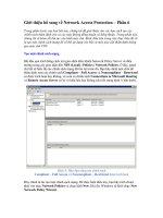
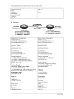
Figure 11.1 shows a diagram of a portion of a company internet-
work. IP addresses (from our range in Table 11.1) have been assigned
to the router interfaces on each of the routers. This figure will help
provide some context to the IOS commands that you are going to
work with in this chapter.
FIGURE 11.1
Two remote sites con-
nected to a central
office. IP addressing pro-
vided for remote sites.
You will configure the 2505 router at the Branch A location. This
means that the router (which has three interfaces, one Ethernet, and
two serial) must have each interface configured with a different IP
address that is in a different subnet range. Table 11.2 lists the IP
addresses (also shown in Figure 11.1) that you will use to configure
this router. You will learn about configuring LAN interfaces (such as
Ethernet ports) in the next section, “LAN Interfaces” and WAN
interfaces in the section after that, “WAN Interfaces.”
1 9 8
Table 11.2 IP Addresses for 2505 Router Interfaces
Interface IP Address
Ethernet 0 130.10.32.1
Serial 0 130.10.64.1
Serial 1 130.10.128.1
SEE ALSO
➤ For an overview of IP routing protocols such as RIP and IGRP, see page 93.
LAN Interfaces
LAN interfaces, such as Ethernet ports or Token Ring ports, will be
the connection point between the router and a local area network.
The number of subnets at a particular location will dictate the num-
ber of LAN interfaces required on the router (if only one router is
used).
Each of these LAN interfaces will be on a separate subnet. The sim-
plest way to assign IP addresses to a LAN interface is to use the first
IP address available in the address range of the subnet that the inter-
face will connect to.
Configuring IP addressing for a LAN interface
1. At the Privileged prompt type config t, and then press Enter.
You are placed in the Global Configuration mode.
2. To configure a particular LAN interface, type the name of the
interface at the prompt, such as interface ethernet 0 . Then
press Enter. The prompt changes to the config-if mode.
3. Now you can enter the ip address command followed by the IP
address for the interface and the subnet mask for the network. In
this example, the command would be ip address 130.10.32.1
255.255.224.0 (see Figure 11.2). Press Enter to complete the
command.
4. To end the configuration of the interface, press Ctrl+Z.
5. Press Enter again to return to the privileged prompt.
PART III Routing LAN Proto cols
CHAPTER 11 Conf iguring IP Rou ting
1 9 9
PART III
Configuring Router Interfaces CHAPTER 11
You can quickly check the configuration parameters for a LAN port
using the show ip interface command. For example, to see the IP
addressing for Ethernet 0, you would type show ip interface e0 and
then press Enter. Figure 11.3 shows the results of this command on
our 2505 router.
FIGURE 11.2
Individual LAN interfaces
must be configured with
an IP address and sub-
net mask.
Show all interface IP
addressing
If you type the show ip
interface command
and don’t specify a
particular router interface,
the IP addressing of all the
interfaces on the router
will be displayed.
FIGURE 11.3
Check the IP addressing
for an interface with the
show ip interface
command.
If you look at the IP information provided in Figure 11.3, the IP
address reads as 130.10.32.1/19, and no subnet mask information is
provided. You entered 130.10.32.1 as the IP address for the interface
in the previous set of steps. So, what does the /19 mean? Actually,
this is the router’s way of telling you the subnet mask.
The 19 is the number of bits that are used for network addressing
plus the number of bits used to create the subnets on this network.
Normally, a Class B network uses two octets (16 bits) to define the
network number for the network: in this case 19–16=3. This shows
you the number of bits stolen for subnetting. If you take the first
three high-order bits and add them (128+64+32), you get 224, which
tells you that the subnet mask is 255.255.224.0.
2 0 0
Whenever you see notation like the /19, just take that number and
subtract the number of bits that are normally used for the class of
network that you are working with. This always gives you the subnet
bits, which can then be used to quickly calculate the subnet mask.
WAN Interfaces
WAN interfaces can be configured with IP addresses exactly in the
same way that you configure LAN interfaces. To configure a serial 0
interface on a router, you would complete the following steps.
Configuring IP addressing for a serial interface
1. At the Privileged prompt, type config t, and then press Enter.
You are placed in the Global Configuration mode.
2. To configure a particular LAN interface, type the name of the
interface at the prompt, such as interface serial 0. Then press
Enter. The prompt changes to the config-if mode.
3. Now you can enter the IP address command followed by the IP
address for the interface and the subnet mask for the network. In
this example, the command would be ip address 130.10.64.1
255.255.224.0 (see Figure 11.4). Press Enter to complete the
command.
PART III Rout ing LA N Protocols
CHAPTER 11 Conf igu rin g IP Routing
Saving your router con-
figuration
When you make changes to
your router’s configuration,
you will want to save the
configuration changes from
RAM to NVRAM. This
makes the currently running
configuration file the
startup configuration if the
router is rebooted or pow-
ered back on after a power
failure. At the privileged
prompt, type copy run-
ning-config
startup-config, and
then press Enter. The con-
figuration will be built and
saved to NVRAM.
FIGURE 11.4
Individual WAN inter-
faces must be config-
ured with an IP address
and subnet mask.
4. To end the configuration of the interface, press Ctrl+Z.
5. Press Enter again to return to the privileged prompt.
You can use the show ip interface s0 command to check the config-
uration of the serial interface.
One issue relating to the number of IP addresses you have available
to configure the routers, hosts, and servers on your network rears its
ugly head when you are configuring WAN interfaces. An entire sub-
net (an entire range of IP addresses) must be wasted to configure the
serial interfaces on two routers that are connected by a particular
WAN connection.
2 0 1
PART III
Conf igurin g a Rout ing Pr otocol CHAPTER 11
For example, in the case of our two 2505 routers in Figure 11.1, they
are connected by their serial 0 interfaces (using a particular WAN
connection and protocol). This connection must be configured as a
separate subnet, meaning the serial 0 interface on the Branch Office
A router will use one address in the chosen subnet range and the ser-
ial 0 interface on the Branch Office B router will use one address
from that same subnet range. So, you basically fritter away all the
other addresses in that subnet range.
To overcome this obvious waste of IP addresses, you can configure
your serial interfaces without IP addresses (they will still route IP
packets even though they are designated as IP unumbered). The com-
mand used at the configuration prompt for the interface is ip unnum-
bered [interface or virtual interface]. The interface or virtual
interface parameter is the designation of an actual interface, such as
Ethernet 0, or a virtual interface such as loopback 0, that has been
configured with an IP address (see Figure 11.5).
FIGURE 11.5
Serial interfaces can be
configured as ip
unnumbered, which
saves IP addressesfor
other routers and nodes
on your network.
If you use ip unnumbered on a serial interface, the serial interface that
it connects to via a WAN connection must also be configured as IP
unnumbered. The drawbacks of configuring a serial interface as IP
unnumbered, is that you cannot Telnet to that serial interface or ping
that interface (because it doesn’t have its own IP address). Also, if the
interface to which you “hooked” the serial port, such as Ethernet 0
(shown in Figure 11.5) goes down, you might not be able to reach
the connection that the serial interface is attached to.
Configuring a Routing Protocol
After you have the interfaces on the router configured with the
appropriate IP addresses and subnet mask, you can configure a rout-
ing protocol. Different Interior Routing Protocols (protocols used
for routing on your internal internetwork) are available and your
choice of a routing protocol will depend on the size of your internet-
work. For example, RIP is fine for small internetworks but is limited
2 0 2
to 15 hops (from router to router), making its use on large internet-
works a problem. For larger internetworks you may want to use
IGRP or OSPF. You will look at the configuration of RIP and the
configuration of IGRP in the next two sections of this chapter.
SEE ALSO
➤ For an overview of IP routing protocols such as RIP and IGRP, see page 93.
Configuring RIP
RIP is a distance-vector routing protocol that uses hop count as its
metric. RIP summarizes the information in the routing table by IP
network numbers (also referred to as major network numbers).
Configuring RIP is very straightforward. You must first select RIP as
your routing protocol and then let RIP know the major network
number for each interface you have enabled for IP routing. In the
sample network that you have been discussing (see Figure 11.1), you
are working with only one major network number, 130.10.0.0. So,
you only need to specify this network when configuring RIP on our
router.
Configuring RIP
1. At the privileged prompt, type config t, and then press Enter.
You are placed in the Global Configuration mode.
2. At the config prompt, type router rip, and then press Enter.
This selects RIP as the routing protocol.
3. Type network [major network number ] at the config prompt. The
major network number is the network address for a class A, B, or
C network that is directly connected to the router. In your case,
you are connected to one major network 130.10.0.0. Therefore,
the command would be network 130.10.0.0 (see Figure 11.6).
Press Enter to continue.
4. Repeat the network [major network number ] for each IP network
that the router is directly connected to. For example, if different
Class C networks are connected to several Ethernet interfaces,
you must repeat the network command for each of the network
addresses for these Class C networks.
PART III Ro uting LAN Proto cols
CHAPTER 11 Configurin g IP Routing
Enabling IP routing
If IP routing has been dis-
abled on the router (it is
enabled by default), you
will want to enable it
before configuring your
routing protocol. At the
config prompt, type the
global command ip
routing, and then press
Enter. To exit the
Configuration mode press
Ctrl+Z. If for some reason
you want to disable IP rout-
ing on a router, you can use
the configuration command
no ip routing.
2 0 3
PART III
Conf ig urin g a Rout ing Pr otocol CHAPTER 11
5. When you have finished entering the directly connected net-
works, press Ctrl+Z to end the configuration session.
6. Press Enter to return to the Privileged prompt.
After you’ve configured RIP on your router, you can use the IOS
commands that provide a view of RIP routing information such as
the routing table and the settings for RIP broadcasts.
To view the RIP routing table, type show ip route at the user or
privileged prompt and then press Enter. Figure 11.7 shows the
results of this command on a 2505 router that is connected to
another 2505 router via a serial connection. Subnets that are directly
connected to the router are marked with a C (interfaces that were
configured on that router). Other subnets that are reached by a par-
ticular directly connected subnet are marked with an R (these net-
work locations are learned by RIP).
FIGURE 11.6
Router RIP selects RIP
as the routing protocol
and the network com-
mand specifiesIP net-
works connected to the
router.
FIGURE 11.7
The show ip route
commandprovides a
view of the RIP routing
table on the router.
You can use the show ip protocol command to view the timing
information related to RIP. For example, RIP updates are sent every
30 seconds. The hold-down time for RIP is 180 seconds. This means
that if a router doesn’t receive a RIP update from a connected
router, it waits 180 seconds from the last received update and then
flags the subnet path as suspect. After 240 seconds, the router will
actually remove the path information related to the other router
from the routing table because it considers the path no longer
usable.
2 0 4
Type show ip protocol at the user or privileged prompt and then
press Enter. Figure 11.8 shows the results of this command.
PART III Rout ing LA N Protocols
CHAPTER 11 Configurin g IP Routing
FIGURE 11.8
The show ip proto -
col command provides
a view of the RIP timing
settings and the net-
worksthat are provided
routing by RIP.
If you want to view RIP update messages as they are sent and
received by a router, you can use the debug ip rip command. Type
debug ip rip at the privileged prompt and then press Enter. Figure
11.9 shows the results of this command.
FIGURE 11.9
Use the debug ip
rip commandto view
RIP updates on the
router.
To turn off RIP debugging, type no debug ip rip and press Enter
(otherwise the update messages will drive you crazy if you are trying
to work on the router).
SEE ALSO
➤ For information on how routers work and using routing protocols to build routing tables, see
page 82.
Configuring IGRP
Because RIP is limited to routes of less than 16 hop counts, interme-
diate and large internetworks need a routing protocol that can handle
the scale of the network. IGRP is a distance vector routing protocol
2 0 5
PART III
Conf igurin g a Rout ing Pr otocol CHAPTER 11
like (RIP) that uses several metrics such as delay, bandwidth, and
reliability. IGRP doesn’t use hop count as a metric but it can provide
routing information for a path of up to 255 hops, which makes it
ideal for large internetworks.
Configuring IGRP is similar to configuring RIP. You must enable
the IGRP protocol and specify the major IP networks that are
directly connected to the router’s interfaces. However, because IGRP
is used on larger internetworks (such as a complete corporate net-
work), you must specify the autonomous system number for the
autonomous system (AS) that the router belongs to. Several different
networks (Class A, B, or C) can be part of a particular autonomous
system. Autonomous systems are tied together by core routers that
run an Exterior Gateway Protocol, such as Border Gateway Protocol
(BGP).
Configuring IGRP
1. At the privileged prompt, type config t, and then press Enter.
You are placed in the Global Configuration mode.
2. At the config prompt, type router igrp [autonomous system num-
ber], where the autonomous system number is the AS number
assigned to the AS to which your router belongs. For example,
router igrp 10 would enable IGRP routing and specify the AS
number 10. After entering the command, press Enter.
3. Type network [major network number ] at the config prompt. The
major network number is the network address for a Class A, B, or
C network that is directly connected to the router. In this case,
you are connected to one major network, 130.10.0.0, so the
command would be network 130.10.0.0 (see Figure 11.10). Press
Enter to continue.
4. Repeat the network [major network number ] for each IP network
that the router is directly connected to. For example, if different
Class C networks are connected to several Ethernet interfaces,
you must repeat the network command for each of the network
addresses for these Class C networks.
Creating autonomous
systems
In cases where a company
merges with another com-
pany or a company’s net-
work grows in leaps and
bounds, you may want to
employ autonomous sys-
tems (you have to if you are
using IGRPas your routing
protocol). Autonomous sys-
tem numbers can be
between 1 and 65,655. You
arbitrarily assign them to
your different internet-
works (but use some kind
of numbering system to
keep it all straight). The
autonomous systems are
then tied together by large
core routers that run an
Exterior Gateway Protocol.
See Appendix C, “Selected
Cisco Router
Specifications,” for infor-
mation on the 7500 series
of Cisco that might be used
as Core routers.
2 0 6
5. When you have entered the directly connected networks, press
Ctrl+Z to end the configuration session.
You can also use the show commands (and variations of these com-
mands related to IGRP) that were discussed in the section on RIP
routing. For example, the show ip route command now shows the
routing table built by IGRP (see Figure 11.11). Network addresses
marked with a C are directly connected to the router; addresses
marked with an I are those discovered by IGRP.
PART III Rout ing LA N Protocols
CHAPTER 11 Configurin g IP Routing
FIGURE 11.10
Router igrp [AS
number] selects IGRP
as the routing protocol
and specifies the
autonomous system that
the router belongs to.
FIGURE 11.11
The show ip route
commandallows you to
view the IGRP routing
table.
IGRP sends updates every 90 seconds (as opposed to RIP’s 30-second
interval). Routes not confirmed for 630 seconds are flushed from the
router’s routing table. You can view this information using the show
ip route command.
To view a summary of the IGRP routing update messages as they exit
and enter the router, use the debug ip igrp events command at the
Privileged prompt. Figure 11.12 shows the results of this command.
If you want to see information related to the update messages such as
the metric used (a number representing a value based on all the
IGRP metrics), use the debug ip igrp transaction command. Figure
11.13 displays the results of this command.
Turn off all that debug-
ging
To turn off all the debug -
ging you may have enabled
on a router, type no
debug all at the
Privileged prompt and then
press Enter.
2 0 7
PART III
Dyna mic Ro uting Versus Static R outin g CHAPTER 11
SEE ALSO
➤ For background information on IGRP, see page 93.
➤ For an overview of Exterior Gateway Protocols, see page 95.
Dynamic Routing Versus Static Routing
The previous two sections of this chapter enabled the router for
dynamic routing. The selected routing protocol (RIP or IGRP)
builds a routing table using information received from neighboring
routers. You can also configure your routers for static routing where
you specify the routes in a static routing table. Static routing also
requires that you update the routing tables manually.
Static routing doesn’t require the use of a routing protocol. You are
in charge of the routing tables. However, static routing should prob-
ably only be used in cases where the internetwork paths are fairly
simple and there is only one route between the network or networks
serviced by your router and another router’s networks. Static routing
tables cannot react to route changes because of lines going down.
FIGURE 11.12
The debug ip igrp
events command
enables you to view the
outgoing and incoming
IGRP updates on the
router.
FIGURE 11.13
The debug ip igrp
transaction
command provides infor-
mation on update mes-
sages sent and received
and the metric value
used.
2 0 8
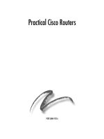
Let’s keep this simple and use two routers that support networks that
have not been subnetted (several different Class C networks). For
example, let’s say you have two routers connected as shown in Figure
11.14. You want to set up a static route from the router at Branch
Office A to the LAN at Branch Office B (Class C network address
194.10.30.0).
PART III Rout ing LA N Proto cols
CHAPTER 11 Configurin g IP Routing
FIGURE 11.14
A small internetworkcan
be configured for static
IP routing.
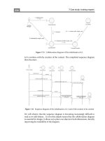
At the configuration prompt (on the Branch Office A router), you
would type the command ip route 194.10.30.0 255.255.255.0
194.10.20.2. This tells your router (at Branch Office A) to build a
static routing table where network 194.10.30.0 (the LAN at Branch
Office B) is reached by the serial connection between the two
routers, with the interface on the Branch Office B router configured
with the IP address 194.10.20.2. Figure 11.15 shows how this com-
mand would look on the router console.
You would have to provide paths for all the routes served by remote
routers for your Branch Office A router. And because you have a
router at Branch Office B, you would have to use the ip route com-
mand to configure its static routing table to LANs serviced by other
routers (such as the Branch Office A router).
2 0 9
PART III
Using Te l n e t CHAPTER 11
As you can see, building your own routing tables statically requires a
lot of up-front work. You would also have to update the tables on all
the routers involved if any of the routes changed.
Static routing does provide you with complete control over the paths
that packets are routed on. However, on large, dynamic internet-
works, dynamic routing is probably the way you will want to go
when configuring your routers.
Using Telnet
One big plus of configuring IP on your router interfaces is that you
can Telnet (connect to) another router using the IP address of one of
its interfaces. For example, you have been working with two 2505
routers connected by a serial cable. The router that you are con-
nected to via a serial connection has an IP address of 130.96.1 on its
Ethernet 0 port and 130.10.64.2 on its Serial 0 port. You can use
either of these IP addresses to gain entry (Telnet) to the other router.
After connecting to the router, you must provide the virtual terminal
password that was configured on the router.
Using Telnet to connect to another router
1. At the user or privileged prompt, type telnet [ip address],
where ip address is the IP address of one of the interfaces on
the other router. To Telnet to the Olive router, directly con-
nected via a serial connection to our Popeye router, type telnet
130.10.96.1 (the IP address of its Ethernet 0 port), and then
press Enter.
2. You are connected to the other router and asked to provide the
virtual terminal password. Type the virtual terminal password,
and then press Enter.
You are now logged on to the other router (see Figure 11.16).
FIGURE 11.15
You configure static
routes using the ip
route command fol-
lowed by the destination
network and the IP
address of the router
interface on the router
that serves the particular
network.
2 1 0
If you know the enable password, you can enter the Privileged mode
on this router and even change the configuration of the router
remotely. When you have finished working on the remote router,
type quit at the prompt. You are logged off the remote router and
returned to the prompt for your local router.
Telnet is a great tool for connecting to remote routers and monitor-
ing or configuring them. It’s as if you are sitting at the console com-
puter directly connected to that router.
SEE ALSO
➤ For information on setting the virtual terminal password when first configuring the router, see
page 129.
PART III Rout ing LA N Protoco ls
CHAPTER 11 Configurin g IP Routing
FIGURE 11.16
You can Telnet to a
remote router to view its
configuration or to con-
figurethe router.
Routing Novell IPX
Introducing IPX/SPX
•
Understanding IPX Addressing
•
Configuring IPX Routing
•
Configuring Router Interfaces with IPX
•
Monitoring IPX Routing
•
12
c h a p t e r