ccna practical cisco routers phần 5 pptx
Bạn đang xem bản rút gọn của tài liệu. Xem và tải ngay bản đầy đủ của tài liệu tại đây (4.47 MB, 39 trang )
1 4 8
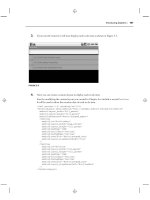
After providing help on the specific command, the command itself is
automatically retyped for you at the command prompt (see Figure
9.4). You can then add specific parameters to the command and press
Enter to execute it. For example, in the case of the show command,
you can add version to the command and then press Enter.
Parameters related to IOS currently installed on the router will be
displayed on the screen (see Figure 9.5).
PART II Router D esign and Bas ic Configuration
CHAPTER 9 Workin g with the Cis co IOS
FIGURE 9.3
You can get help in any
of the router modes; type
? and then press Enter.
FIGURE 9.4
You can get help on
specific commands.
1 4 9
PART II
Router Examination Commands CHAPTER 9
As stated before, the help system is also available in the Privileged
and Configuration modes. The Privileged mode help is similar to
that found in the User mode. You can receive general help by typing
? or more specific help by typing a command followed by ?.
Figure 9.6 shows the Help screen for the Privileged mode. Notice
that it provides a larger number of commands than the User mode
(which makes sense because the Privileged mode is a password-
protected mode that provides greater access to the router).
You can also get help in the Configuration mode. For example, you
may be in the middle of configuring a particular router interface and
would like to see a list of subcommands available. Type ? at the con-
figure interface prompt and you will receive a list of available com-
mands, as shown in Figure 9.7.
Router Examination Commands
When you work in the Exec modes (User and Privileged) a number
of the commands you use center around examining the various con-
figuration settings and hardware parameters of the router. One of the
most useful commands is the show command. You can use this com-
mand to view the status of all the interfaces on the router and view
the statistics for such items as Flash RAM and the network protocols
FIGURE 9.5
Use the Help system to
correctly enter a particu-
lar command.
Help information
Completed command
Results of command
How to get more
When theinformation
provided by a particular
command (such as ?)
doesn’t fit on one console
screen, More will appear
at the bottom of the dis-
played information. To
move down through the
additional information,
press Enter to advance one
line and press the
Spacebar to advance one
screen. In cases where you
don’t want to view more
information, and want to
return to the console
prompt, press Escape
(Esc).
1 5 0
currently being routed. You will find the show command invaluable in
both the User and Privileged modes.
PART II Router D esign and Bas ic Configuration
CHAPTER 9 Workin g with the Cis co IOS
FIGURE 9.6
The Privilegedmode
provides a larger set of
commands than the User
mode does.
FIGURE 9.7
Help is availableeven in
the Configuration mode.
1 5 1
PART II
Router Examination Commands CHAPTER 9
You’ve already seen in the preceding section that the User mode pro-
vides you with a set of commands that you can use to examine the
router status, and it is actually a subset of commands that are avail-
able to you in the Privileged mode. And even though you are work-
ing with a subset of types of items you can view with the show
command, you can actually learn quite a lot about how the router
has been configured in the User mode.
So, suppose you are stuck in the User mode on a router (you don’t
have the Privileged mode password) and want to examine the router.
The first thing you would like to view is the interfaces available on
the router.
Using the show interfaces command
1. At the User prompt, type show interface.
2. Press Enter to execute the command.
The results of the command will appear on the router console
screen. Figure 9.8 shows the results of the show interfaces command
on a 2505 router that has one Ethernet and two serial interfaces. It
shows one screen-full of information; to see the rest of the output,
you would have to press the Spacebar.
Quite a lot of information is provided by this one command. The
hardware address (MAC) and the IP address are shown for Ethernet
0. The status of the interface (such as up or down) and the status of
the protocol (or protocols) configured on that interface also appear.
Additional information relates to the number of packets that have
been input and output by the interface. Because this is an Ethernet
interface (which uses CSMA/CD as the network access strategy), the
number of collisions and illegal frames (giants and runts) are also
provided.
Information on the other interfaces on the router will also be pro-
vided by this command. Note the Serial 0 interface information
shown in Figure 9.8. The IP address for the interface is shown and
the encapsulation type, PPP (which is the WAN protocol being used
on this interface).
Command-line savvy
When you are working with
the CLI there are some key-
strokes that will help you if
you make a mistake in a
command and want to edit
it before you execute it.
Press Backspace to
delete characters to the
left of the cursor and then
retype them. If you need to
move to the beginning of
the command line, press
Ctrl+A. To move to the end
of the line press Ctrl+E.
Remember that you must
press the Enter key to
execute your commands.
1 5 2
The show interfaces command will give you information on all the
interfaces on a particular router. In the case of the 2505 router, I
would have to press the Spacebar to show the next screen so that I
can see the parameters related to the Serial 1 interface on the router.
If you are using a higher-end router with several interfaces, you will
have to continue to press Enter or the Spacebar to view the infor-
mation. When you have come to the end of the information pro-
vided by the command, you will be returned to the user prompt.
If you find that show interfaces provides you with more information
than you need and you just want to hone in on a particular interface
on the router, you can use the show command to view the parameters
related to just one interface.
Narrowing the focus of the show command
1. At the user prompt, type show interface Ethernet 0.
2. Press Enter to execute the command.
You will see results similar to those shown in Figure 9.8, but only the
information for the Ethernet 0 interface will be provided.
PART II Router D esign and Bas ic Configuration
CHAPTER 9 Workin g with the Cis co IOS
FIGURE 9.8
The show
interfaces command
gives you information
related to the interfaces
installed on the router.
Ethernet interface
hardware address
(0010.7b3a.50b3)
Ethernet interface IP
address (130.10.64.1/19)
Ethernet encapsulation
type (Encapsulation
ARPA)
Serial 0 IP address
(130.10.32.1/19)
Serial 0 encapsulation
type (Encapsulation
PPP)
1 5 3
PART II
Using th e Privileged Mode CHAPTER 9
The show command can also be used to gather other information
related to the router. Table 9.1 lists some of the additional show-
related commands that you can use in the User mode (all these show
derivations will also work in the Privileged mode).
Table 9.1 The show Command in the User Mode
Command Provides
Show clock The time and date settings for the router
Show version The version of the IOS currently running on the router
Show protocols Lists the network protocols configured on the router
Show processes CPU utilization information
Show history A list of your last 10 commands
Show hub Information on the status of the hub ports of a 2505 router
A number of other show-related commands exist. I will discuss several
more show commands in the context of the particular network or
routing protocol that they are used to monitor.
SEE ALSO
➤ For more information on using show to view IP-related parameters,see page 195.
➤ For more information on using show to view IPX-related parameters,see page 211.
➤ For more information on using show to view AppleTalk-related parameters,see page 227.
Using the Privileged Mode
The Privileged mode also allows you take advantage of all the show
commands discussed in the previous section and several others that
aren’t available in the User mode. You will learn some of these “priv-
ileged” show commands, such as show running-config, in the
“Checking Router Memory” section of this chapter.
More importantly, the Privileged mode provides you with the
capability to access more complete information on the router’s
configuration and set operating system parameters (and you already
know that you must be in the Privileged mode to enter the router’s
Abbreviate your com-
mands
You will find that the Cisco
IOS commands can be
abbreviated in many cases.
For example, rather than
typing the show command,
you can get away with the
abbreviation sh. The
abbreviated form of
interface
Ethernet 0 would be
int E0. So the entire
command to show
interface
Ethernet 0 would be
sh int E0. Try your
own abbreviated forms of
commands as you work
with your router. The worst
thing that will happen is
that the command inter-
preter won’t recognize the
command and let you know
that there was invalid input
oran incomplete command.
1 5 4
Configuration mode). Let’s say that you would like to set the system
clock for the router; you must do it in the Privileged mode.
Setting the time and date
1. At the User prompt, type enable, and then press Enter.
2. Type the Privileged mode password and press Enter. You are
now in the Privileged mode.
3. Type clock set followed by the time, day, month, and year; a
correct entry for the time would be clock set 21:43:05 (hour,
minutes, seconds); a correct entry for the date would be 13 June
1999. Using the example data shown, the complete command
would read clock set 21:43:05 13 June 1999, as shown in
Figure 9.9.
4. Press Enter to execute the command.
5. To check the new settings type show clock, and then press Enter
(see Figure 9.9).
PART II Router D esign and Bas ic Configuration
CHAPTER 9 Workin g with the Cis co IOS
FIGURE 9.9
You can set the time and
dateon the router using
the clock set
command.
The clock set
command
Several other Privileged commands exist that you will use on a regu-
lar basis. For example, show cdp neighbors is an internetwork
exploratory tool that I will discuss in the “Checking Out the
Internetwork Neighborhood” section found later in this chapter.
Other Privileged commands are discussed in the next section.
Checking Router Memory
When you configure the various interface and protocol parameters
for a router, this information is stored in the router’s RAM. It’s
important that you store this information somewhere, in case the
router loses power. In the Privileged mode you can save your run-
ning configuration to NVRAM where it becomes the router’s startup
configuration (and is loaded if the router is rebooted).
1 5 5
PART II
Checking Router Me mory CHAPTER 9
The Privileged mode also allows you to examine the contents of
RAM and NVRAM using the show command. These commands
aren’t available in the User mode.
Viewing the running configuration
1. At the User prompt, type enable, and then press Enter (if you
aren’t in the Privileged mode).
2. Type the Privileged mode password and press Enter. You are
now in the Privileged mode.
3. Type show running-config, and then press Enter to execute the
command. The command results will appear on the router (see
Figure 9.10).
4. To advance through the information on the screen, press
Spacebar for an entire screen or Enter to advance line by line.
FIGURE 9.10
Show running-
config displaysthe
entire running
configuration for the
router.
The running configuration provides information on how the different
interfaces are currently configured and which routing protocols have
been enabled. It also shows the passwords that have been set on the
router (however, remember that the Privileged mode secret pass-
word is encrypted, so you can’t tell what it is). The running-config
command provides a complete picture of the parameters running on
the router, and this is why it is a Privileged mode command; it’s
information important to the router’s administrator, so it should be
protected.
1 5 6
As you fine-tune your running configuration, a time will come when
you would want to save it to NVRAM as the startup configuration.
The great thing about the copy command is that you can copy infor-
mation from RAM to NVRAM (running to startup). Or if you mess
up your running configuration, you can copy information from
NVRAM to RAM (startup to running). The command you use to
copy information from one type of memory to another is copy.
Copying the running configuration
1. In Privileged mode, type copy running-config startup-config.
2. Press Enter to execute the command.
The router will pause for a moment. Building configuration will be
displayed on the screen. Then “[OK]” will appear. The running
configuration has been copied to the startup configuration. You can
quickly check your new startup configuration with the show startup-
config command (the output will be similar to the running-config
shown in Figure 9.10). The results of this command also show you
how much NVRAM is being used on the system to store the config-
uration file.
Another memory type on the router is Flash RAM. This is where the
router’s IOS is stored. You can view the contents of Flash in both the
User and Privileged mode.
Viewing Flash contents
1. In the Privileged or User mode, type show flash.
2. Press Enter to execute the command.
The results of the command will appear on the console screen (see
Figure 9.11). The IOS filename is given and the amount of free and
used Flash RAM is displayed.
PART II Router D esign and Bas ic Configuration
CHAPTER 9 Workin g with the Cis co IOS
Scroll through a list of
recent commands
You can use the Up Arrow
key on the keyboard to
cycle through the com-
mands that you recently
used. Press the Up Arrow
and you will see the last
command used (it is placed
at the router prompt); con-
tinue to press the Up Arrow
and your commands (the
last 10 from most to least
recent) will appear one by
one. To fire off a recycled
command, just use the Up
Arrow key to place the
appropriate command at
the prompt, and thenpress
Enter.
Remember to exit the
Privileged mode
When you finish working in
the Privileged mode type
disable, and then press
Enter to return to the User
mode. This will protect
your router from being
reconfigured by an overly
zealous coworker or corpo-
rate terrorist who is trying
to bring down your Silly
Putty manufacturing
empire.
FIGURE 9.11
show flash displays
the IOS file in flash and
the amount of flash
available.
OS filename
1 5 7
PART II
Checking Out the Internetwork Neighborhood CHAPTER 9
Checking Out the Internetwork
Neighborhood
When you work with internetworks, it’s important to be able to
gather information related to routers that are directly connected to
your router. These routers are typically referred to as neighbors.
Cisco routers have a proprietary protocol, Cisco Discovery Protocol
(CDP), that provides you with the capability to access information
related to neighboring routers. CDP uses Data Link broadcasts to
discover neighboring Cisco routers that are also running CDP (CDP
is turned on automatically on routers running IOS 10.3 or newer).
Working with CDP
Before you use CDP to view information about other routers, you
may want to check your router interfaces to make sure that CDP is
enabled. This is done using the show cdp interface command.
Viewing CDP interfaces
1. At the User or Privileged prompt type show cdp interface .
2. Press Enter to execute the command.
The results of the command will appear on the router console screen
(see Figure 9.12). The CDP information for all the interfaces on the
router will appear.
Make sure your running
configuration works
You will want to put a new
running configuration
through its paces (let it run
for a while and monitor
router parameters using the
show command and a
command I haven’t dis-
cussed yet called debug)
before you save it as the
router’s startup configura-
tion. You may also want to
back up the original startup
configuration to a TFTP
server before you save a
new running configuration
as the startup configuration
(covered in Chapter 17).
FIGURE 9.12
The show cdp
interface command
shows which interfaces
are enabled for CDP.
1 5 8
You can also view the CDP information for a particular interface.
For example, in Figure 9.12, the command that follows the initial
show cdp interface command is show cdp interface s0. This pro-
vides the CDP information for just interface serial 0.
In Figure 9.12, you will see two pieces of information that warrant
further discussion: the CDP packet send interval and the CDP hold-
time. Notice that CDP packets are sent by CDP-enabled interfaces
every 60 seconds. This means that they are broadcasting information
to their CDP neighbors every minute.
The holdtime refers to the amount of time a router should hold the
CDP information that it has received from a neighboring router. If a
router doesn’t receive an update message from a neighbor within
three minutes (180 seconds), it must discard the old CDP informa-
tion that it holds.
Remember that the purpose of CDP is to stay up to date on the sta-
tus of your neighboring routers. So, if a line is down or some other
problem causes you to lose contact with a neighbor, you don’t want
your router relying on old information when it makes routing deci-
sions.
If a particular interface isn’t enabled for CDP, you can enable it in
the configuration mode.
Enabling CDP on an interface
1. At Privileged prompt type config terminal. You are placed in
the configuration mode with the console (terminal is the source
for the configuration information).
2. At the Config prompt type the interface you want to enable for
CDP, such as interface serial 0. Then press Enter. The
prompt changes to the Config-If prompt, letting you know that
you can now enter information for the configuration of the
designated interface.
3. Type cdp enable, and then press Enter.
4. To end the configuration of the serial interface, press Ctrl+Z.
You will be returned to the Privileged prompt (see Figure 9.13).
PART II Router D esign a nd Basic Configuration
CHAPTER 9 Workin g with the Cis co IOS
Working with flash
You erase the contents of
Flash in the Privileged
mode(not generally a good
idea) using the erase
command; you can also
load a new version of the
IOS into Flash using a TFTP
server and the copy com-
mand, which is discussed
in Chapter 17.
CDP doesn’t care about
network protocols
CDP is platform-
independent, so it will
accumulate information
about neighbor routers no
matter which network
protocol stack they might
be running (such as TCP/IP,
IPX/SPX, and so on).
Changing CDP holdtime
You can manually set the
holdtime for CDP in the
configurationmode. At the
configuration prompt type
cdp holdtime
seconds, where
seconds is the time
interval for the holdtime.
1 5 9
PART II
Viewing CDP Neighbors CHAPTER 9
Viewing CDP Neighbors
After you have viewed the status of CDP on your various
interfaces, you can use CDP to take a look at platform and
protocol information on a neighboring router or routers.
Viewing CDP neighbors
1. At the User or Privileged prompt type show cdp neighbors .
2. Press Enter to execute the command.
Figure 9.14 shows the result of this command for a 2505 router that
only has one neighbor, which is connected via a serial interface.
Table 9.2 describes the information shown in Figure 9.14.
FIGURE 9.13
You can easily enablean
interface for CDP if it has
been previously dis-
abled.
FIGURE 9.14
The show cdp
neighbor command
lets you check your
network neighborhood
and view directly
connected routers.
Table 9.2 The show Command in the User Mode
Parameter Meaning Example from Figure 9.14
Device ID The neighbor’s or neighbors’ Olive
hostname(s)
Local Interface The interface on the local Serial 0
router that provides the
connection to the neighbor
Capability Whether the router is R (this router is only
configured to serve configured to route)
multiple functions such as
routing (R), Bridging (B),
and switching (S).
continues…
1 6 0
Platform The type of Cisco router. 2505 (the neighbor is a 2505
router)
Port ID The interface used on the Serial 0
neighbor to connect to your
local router
Obviously, if you are using a higher-end router that is connected to
many different neighbors via its various interface ports, the number
of neighbors shown using the show cdp neighbors command would
be greater than that shown in Figure 9.14.
If you want to see more details concerning your CDP neighbors, you
can use the show cdp neighbor details command. You can enter this
command at the User or Privileged prompt. Figure 9.15 shows the
results of this command. Notice that this command provides the IP
address of the neighbor’s interface and the version of the IOS that
the neighbor is running.
Using Ping
A command that can be very useful when you are working with
routers is ping. And if you use the Internet a great deal you may have
already used this command to test the lag time between you and
another computer on the Net. Ping (which is short for Packet
InterNet Groper) is used to test the connection between two or more
nodes on a network. These nodes can be host computers, servers, or
routers.
Ping can be used with a number of Layer 3 protocols such as IP,
IPX, and AppleTalk, and uses the logical address assigned to the
node on the network. On routers, you can Ping different interfaces
because in most cases they will each be assigned a logical address.
For example, if you are routing IP, each interface on your router will
probably be assigned an IP address.
For example, let’s say you want to see whether your connection to
another router is up and running. All you have to do is ping the
interface on the other router that your router is connected to.
PART II Router D esign and Bas ic Configuration
CHAPTER 9 Workin g with th e Cisco IOS
Table 9.2 Continued
Parameter Meaning Example from Figure 9.14
Disabling and enabling
CDP
CDP can bedisabled glob-
ally or on an interface-by-
interface basis. To disable
CDP globally, enter the
Configuration mode and
type no cdp run .
This shuts it off on all
interfaces. For a particular
interface, enter the
Configuration mode,
specify the interface you
want to disable, and then
use the command no cdp
enable. The global com-
mand for turning CDP on is
cdp run and is used at
the Privileged prompt.
1 6 1
PART II
Creating a Router Ba nner CHAPTER 9
Pinging a neighbor
1. At the User or Privileged prompt type ping ip address . In this
case you are trying to ping the Olive router that is connected to
your router via a serial interface. So, the command reads ping
130.10.32.2.
2. Press Enter to execute the command.
The results of the Ping command appear in Figure 9.15. Notice that
the success rate is 100%. In cases where you can’t reach the node
that you’ve pinged, the success rate will be 0%.
FIGURE 9.15
ping can be used to
check your connection
to a particular router on
the internetwork.
Ping will be discussed in more detail later in this book (as will the
Trace and Extended Ping commands in Chapter 18, “Basic
Troubleshooting”).
SEE ALSO
➤ For more about ping and extended ping,see page 314.
➤ Another TCP/IP protocol stack member, Telnet,can also be used to connect to other routers on
the internetwork. For more information,see page 209.
Creating a Router Banner
You have explored the Cisco IOS in the User and Privileged mode
(and worked with a number of different and useful IOS commands)
in this chapter, and you should also spend some time working in the
Configuration mode. Because several chapters are devoted to config-
uring specific LAN, WAN, and routing protocols on the router, let’s
work on something fun in the Configuration mode—the creation of
a banner. This banner will appear on your console screen when the
router is booted (or rebooted) and will also appear on the screen of
virtual terminals that are used to log in to your router (using Telnet,
which is discussed in Chapter 11, “Configuring IP Routing”).
1 6 2
The router banner is created in the Configuration mode. The com-
mand is banner motd end character; where the end character is a
keyboard character of your choice that tells the configuration mode
when you have completed your banner text (motd actually stands for
message of the day). For example, you will want to choose a charac-
ter such as the number sign (#), dollar sign ($), or other character
that will not appear in the body of your banner (such as most letters
of the alphabet).
Creating a router banner
1. At the Privileged prompt type config terminal. You are placed
in Configuration mode with the console (terminal is the source
for the configuration information).
2. I will use the dollar sign ($) as our end character. Type banner
motd $. Then press Enter. You will be told to type your banner
text and end the banner with the $ character.
3. Type the text for your banner. Use the Enter key to place blank
lines in the banner text. Use the Spacebar to position items
from left to right in the banner. Figure 9.16 shows a sample
router banner.
4. Type your selected end character ($ in this case) and press
Enter. You will be returned to Configuration mode.
5. Press Ctrl+Z to save your banner and exit Configuration mode.
PART II Router Design a nd Basic Configuration
CHAPTER 9 Workin g with the Cis co IOS
FIGURE 9.16
You can create a banner
for your router in the
configuration mode.
After exiting the Configuration mode, you may have to press Enter
once to return to the Privileged prompt. To view your router banner,
type quit and press Enter.
This exits you from the router. When you press Enter on the initial
router screen, your router banner will appear (see Figure 9.17). If
you have set up the router with a login password, you will be asked
to provide the password to enter the router.
1 6 3
PART II
Creating a Router Ba nner CHAPTER 9
As you can see from this chapter, the Cisco IOS provides a large and
robust command set. You will remember the commands that you use
often and probably have to look up the commands that you don’t. A
summary of the basic commands covered in this book is available in
Appendix A, “Basic Router Command Summary,” as a resource.
SEE ALSO
➤ For more information on setting passwords on the router (in the Configuration mode),
see page 137.
➤ The password commands also appear in the command reference in Appendix B; see page 323.
FIGURE 9.17
Your banner will appear
when you attempt to log
on to the router.
ROUTING LAN PROTOCOLS
III
TCP/IP Primer 167 10
Configuring IP Routing 195 11
Routing Novell IPX 211 12
Routing AppleTalk 227 13
p a r t
The TCP/IP Protocol Stack
•
TCP/IP and the OSI Model
•
Working with IP Addresses
•
Subnetting IP Addresses
•
Creating Class B and Class C Subnets
•
A Final Word on Subnetting
•
10
c h a p t e r
1 6 8
The TCP/IP Protocol Stack
TCP/IP (Transmission Control Protocol/Internet Protocol) has
become the common language for the networking world and is a
commonly deployed protocol suite on enterprise networks. It is also
the foundation for the worldwide Internet—the mega network of
networks. Many network operating systems (NOS), such as Windows
NT 4.0 Server, Windows 2000 Server, and Novell Netware 5.0,
embrace TCP/IP as their default networking protocol.
I discussed TCP/IP briefly in the Chapter 2, “The OSI Model and
Network Protocols.” And as you already know, TCP/IP was devel-
oped originally as a set of WAN protocols that could be used to
maintain communication links between sites even if certain sites
became inoperable during a worldwide nuclear war. In light of the
kind of fun people have on the Internet today using the TCP/IP
stack, it is somewhat ironic (and somewhat depressing) that the suite
was originally developed as a sort of wartime network failsafe system
by the Department of Defense.
Another point that must be made about TCP/IP is that it has
become an integral part of operating and supporting routers on an
internetwork. Cisco router administrators use Telnet (a member of
the TCP/IP stack) to communicate with remote routers and use
TFTP (another TCP/IP protocol) as a mechanism for copying and
saving configuration files and loading new IOS software on the
router. Most big networks use TCP/IP as their network protocol, so
a lack of understanding of the TCP/IP stack will make it pretty hard
for you to work with routers and internetworks. TFTP is discussed
in more detail in Chapter 17, “Using a TFTP Server for Router
Configuration Storage.”
SEE ALSO
➤ To check out some of the other overview information on TCP/IP, see page 45.
TCP/IP and the OSI Model
TCP/IP was developed in the 1970s and so preceded the completion
of the OSI model (in the 1980s). This means that the different
protocols in the TCP/IP stack don’t map directly to a single layer in
PART III Rout ing LAN Protocols
CHAPTER 10 TCP/IP Primer
1 6 9
PART III
TCP/IP an d the OSI Model CHAPTER 10
the OSI model (although the lower-layer Network and Data Link
protocols, such as IP and ARP, do map somewhat closely to their
conceptual equivalent in the OSI model).
When TCP/IP was developed, the Department of Defense (DOD)
developed its own conceptual model—the DOD model—(also known
as the DARPA model) for how the various protocols in the TCP/IP
stack operate. This reference model divides the movement of data
from a sending node to a receiving node into four layers (compared
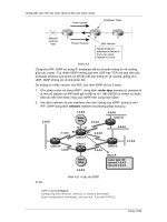
to the seven layers of the OSI model). Figure 10.1 shows how the
DOD model maps to the OSI model.
FIGURE 10.1
The DOD four layer
modelmapped to the
seven layers of the OSI
model.
Each layer in the DOD-TCP/IP conceptual stack defines the job
that TCP/IP protocols do that operate at that particular level (just as
the OSI model does). In the next four sections you will take a look at
what happens at each layer of the DOD-TCP/IP conceptual stack
and the actual TCP/IP stack protocols that operate at these levels.
Figure 10.2 shows the TCP/IP stack mapped to the DOD model.
SEE ALSO
➤ To review the OSI model, see page 34.
1 7 0
Application Layer
The Application layer protocols provide the user interface for the
various protocols and applications that access the network.
Application layer protocols in the TCP/IP stack handle file transfer,
remote login to other nodes, email functionality, and network moni-
toring. A number of different protocols reside at this level:
■ FTP (File Transfer Protocol) is a protocol that provides the capa-
bility to transfer files between two computers. FTP is actually a
full-blown application (FTP clients can be downloaded from the
Internet and used to move files between computers) and a proto-
col that is supported by other applications such as Web
browsers.
■ TFTP (Trivial File Transfer Protocol) is a stripped down version of
FTP that provides a way to move files without any type of
authentication (meaning no username or password). TFTP is
used in the router world as a way to save router configuration
files or update the IOS of a router (this protocol is described
extensively in Chapter 17).
■ SMTP (Simple Mail Transport Protocol) is a protocol that provides
mail delivery between two computers. It is a protocol supported
by email clients and used for sending and receiving email on the
Internet.
■ SNMP (Simple Network Management Protocol) is a protocol that
provides the capability to collect network information. SNMP
uses agents (software watchdogs that keep an eye on network
processes) that collect data on network performance. The col-
lected data can then be compared to baseline information.
Software packages like CiscoWorks use SNMP to help network
administrators monitor the relative health of a network.
■ Telnet is a terminal emulation protocol that allows you to con-
nect a local computer with a remote computer (or other device
such as a router). The local computer becomes a virtual terminal
that has access to applications and other resources on the remote
computer. Telnet will be used to log on to a remote router from
a local router in Chapter 11, “Configuring IP Routing.”
PART III Rout ing LAN Protocols
CHAPTER 10 TCP/IP Prim er
1 7 1
PART III
TCP/IP an d the OS I Model CHAPTER 10
Host-to-Host Layer
The Host-to-Host layer protocols provide flow control and connec-
tion reliability as data moves from a sending to a receiving computer.
This layer takes the data from the Application layer protocols and
begins the process of readying the data for movement out over the
network. Two TCP/IP suite protocols inhabit the Host-to-Host
layer: TCP and UDP.
■ TCP (Transport Control Protocol) is a connection-oriented proto-
col that provides a virtual circuit (not unlike establishing a phone
call between the sending and receiving nodes) between user
applications on the sending and receiving machines. TCP takes
the data from the Application layer protocols and breaks it into
segments and then makes sure that they are reassembled on the
receiving end. TCP requires that the sending and receiving
computer establish a synchronized connection, which is done by
the exchange of packets carrying sequencing numbers and a
synch control bit. TCP requires a lot of network overhead.
■ UDP (User Datagram Protocol) is a connectionless transport
protocol that provides a connection between Application layer
protocols that don’t require the acknowledgements and synchro-
nization provided by TCP. UDP is like sending a postcard
through the mail system. The packet is addressed for the receiv-
ing node and sent on its way. UDP is much more passive than
TCP. Application layer protocols that use UDP include TFTP
and SNMP.
Internet Layer
The Internet layer (corresponding to the OSI Network layer) is
responsible for the routing of data across logical network paths and
provides an addressing system to the upper layers of the conceptual
model. This layer also defines the packet format used for the data as
it moves onto the internetwork. The Internet layer really revolves
around one protocol—IP. Other protocols at this layer basically pro-
vide support for the IP addressing system and packet format. An
important job of the Internet layer is resolving logical addresses
(such as IP addresses) to the actual hardware (MAC) addresses of the
nodes on the network.
IP datagrams are sur-
rounded by MAC layer
information
IP datagrams consist of an
IP header, which contains
the source IP address, the
destination IP address (and
some other IP related
items), and the data pro-
vided by the upper-layer
protocols. This datagram is
sandwiched inside MAC
layer header (containing
information regarding the
media access type, such as
Ethernet or Token Ring) and
MAC layer trailer, which
contains the CRC check for
the packet. In our DOD dia-
gram the MAC layer proto-
cols operated at the
Network Access layer
(described in the next sec-
tion) and at the Data Link
layer of the OSI model. This
IP datagram is a good
example of how the layers
work together to get data
to itsdestination.
1 7 2
■ IP (Internet Protocol)—IP takes the data from the Host-to-Host
layer and fragments the information into packets or datagrams. It
labels each packet with the IP address of the sending device and
the IP address of the receiving device. IP also reassembles data-
grams on the receiving machine into segments for the upper-
layer protocols. IP is a connectionless protocol that has no
interest in the contents of the datagrams. Its only desire is to
address and move the datagrams toward their destination.
■ ARP (Address Resolution Protocol)—When IP prepares a datagram,
it knows the IP address of the sending and receiving computers
(it receives this information from the upper layer protocols such
as Telnet or SMTP). IP also needs the MAC hardware address
for the receiving computer because it must provide this informa-
tion to the Network Access layer protocol used on the network
(such as Ethernet). ARP provides the mechanism for resolving
the IP address to an actual hardware address. ARP sends out
broadcasts with the receiving computer’s IP address and asks the
computer to reply with its hardware address.
■ ICMP (Internet Control Message Protocol)—This protocol is a mes-
sage service provider and management protocol that is used by
routers to send messages to host computers that are sending data
that must be routed. Routers can let the sending host know
when a destination is unreachable or when the router’s memory
buffer is full of data. Again, ICMP is basically used as a support
protocol for IP addressing as ARP is.
➤ The logical addressing system provided by IP is discussed in greater detail later in this chapter
on page 180.
Network Access Layer
The Network Access layer consists of the protocols that take the
datagrams from the Internet layer and envelope them in a specific
frame type that is then placed on the network’s physical medium as a
bit stream. You are already familiar with these protocols, which were
previously described as the Data Link layer protocols of the OSI
model and include such network architectures as Ethernet, Token
Ring, and FDDI. The IEEE specifications described in Chapter 2
provide the specifications for the different frame types used by these
network architectures.
PART III Rout ing LAN Protocols
CHAPTER 10 TCP/IP Primer
Everything you ever
wanted to know about IP
The entire TCP/IP stack a n d
IP in particular (RFC 791)
have been documented in
RFC (Request For Comments)
documents. These docu-
ments are available at a
number of sites on the Wo r l d
Wide Web. Two locations
that are good bets for finding
a particular RFC are Ohio
S t a t e ’s RFC repository at
h t t p : / / w w w . c i s . o h i
o - s t a t e . e d u / h y p e r-
t e x t / i n f o r m a t i o n / r
fc.html, and the Hyper-
RFC siteat http://
www.csl.sony.co.jp
/rfc/. Or you can just
search the Web with RFC
as your keyword.
Ping and traceroute use
ICMP
Both ping and traceroute, a
router command, use ICMP
messages. Ping is intro-
duced in Chapter 9,
“Working with the Cisco
IOS,” and traceroute will be
looked at in Chapter 18,
“Basic Router
Troubleshooting.”