ccna practical cisco routers phần 4 ppsx
Bạn đang xem bản rút gọn của tài liệu. Xem và tải ngay bản đầy đủ của tài liệu tại đây (4.44 MB, 39 trang )
1 0 9
PART II
Logical Interfaces CHAPTER 6
Because the router serves as such an important link between inter-
networks, you don’t want it dumping data packets if a particular
physical interface goes down on the router. So the Loopback virtual
interface is created and configured as the termination address for the
Border Gateway Protocol (BGP) sessions. In this way the traffic is
processed locally on the router, which assures you that the packets
get to their final destination.
Null Interfaces
Another logical interface is the Null interface. It is set up on a router
using the appropriate router commands and serves as a brick wall
that can be used to keep out certain traffic. For example, if you don’t
want traffic from a particular network to move through a particular
router (but move through the internetwork by other routes) you can
configure the Null interface so that it receives and dumps any pack-
ets that the network sends to the router. Normally Access lists (dis-
cussed in Chapter 14, “Filtering Router Traffic with Access Lists”)
are used to filter traffic on an internetwork and define valid routes
for certain networks. The Null interface is pretty much a sledgeham-
mer approach to a process that is normally handled with jeweler’s
tools.
Tunnel Interfaces
A Tunnel interface is another logical interface that can be used to
move packets of a particular type over a connection that doesn’t typi-
cally support these types of packets. For example, a Tunnel interface
can be set up on each of two routers that are responsible for routing
AppleTalk packets from their LANs. These two routers are con-
nected by a serial connection (see Figure 6.7). The Tunnel interface
can be configured to route IP. And although AppleTalk would not be
typically routed over an IP interface, the AppleTalk packets are
encapsulated (stuffed in a generic envelope) and then moved across
the Tunnel as if they were IP packets. Cisco routers provide the
Generic Route Encapsulation Protocol (GRE), which handles the
encapsulation of packets moved over a Tunnel interface.
1 1 0
PART II Router Design a nd Bas ic Configuration
CHAPTER 6 Un derstanding Router Interfaces
FIGURE 6.7
AppleTalk packets are
routed over a virtual IP
Tunnel.
Setting Up a New Router
Becoming Familiar with Your Router
•
Cisco Router Design
•
Connecting the Console
•
Configuring the Router Console
•
Working with the Terminal Emulation
•
Software
Connecting the Router to the Network
•
A Final Word on Physical Router
•
Connections
7
c h a p t e r
1 1 2
Becoming Familiar with Your Router
Routers provide the hardware and software necessary for routing.
They are important internetworking devices for connecting LAN
subnets and for making wide area connections between subnets.
Chapter 5, “How a Router Works,” provided the theory behind how
a router works, and now we will take a look at the nuts and bolts of
actually getting a router out of the box and ready for deployment on
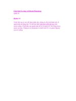
the network. Figure 7.1 shows the front and back of the Cisco 2505
router. The 2505 router provides only three interfaces, one LAN and
two serial interfaces, and is typically used to connect subnets over
serial connections such as ISDN, T1 leased lines, and other WAN
alternatives.
PART II Router Design a nd Bas ic Configuration
CHAPTER 7 Se tting Up a New Router
FIGURE 7.1
The Cisco 2505 router is
typically used to connect
LANs over serial con-
nections.
Ethernet port/hub
Serial ports
Several different Cisco Router models are available; each designed to
satisfy a particular networking or set of networking needs. The num-
ber of ports and the type of ports on the different router models will
vary, and rightly so because you will want to acquire a router
1 1 3
PART II
Cisco Router Design CHAPTER 7
(or routers) with the appropriate connections to fill your internet-
working requirements. (Many of the higher-end routers allow you to
customize the type and number of interfaces found on the router.)
Cisco Router Design
Cisco routers must be able to build routing tables, execute com-
mands, and route packets across network interfaces using routing
protocols. This means that the router must have processing power,
some sort of storage capacity, and available random access memory.
Appropriate software such as an operating system that can be used to
configure routed and routing protocols is also necessary (and is dis-
cussed in Chapter 9, “Working with the Cisco IOS”).
Router CPUs
Routers aren’t unlike PCs in that they contain a microprocessor. And
just like PCs, different Cisco router models come with different
processors. For example, the Cisco 2505 Router (which is the router
that you will see in the various figures throughout this book) con-
tains a 20MHz Motorola 68EC030 processor. A higher-end router
like the Cisco 7010 Router contains a 25MHz Motorola MC68040
CPU. (Many of the lower-end routers use some of the same
Motorola processors that are used in a variety of Apple Macintosh
computers. Some of the very high-end routers use Risc processors
that you would typically find on miniframe computers or very high-
end servers.)
SEE ALSO
➤ For more information on specific Cisco routers,see page 337.
Router Memory Components
As already mentioned, routers not only need processing power, they
also need a place to store configuration information, a place to boot
the router operating system (IOS), and memory that can be used to
hold dynamic information as the router does its job of moving pack-
ets on the internetwork. Cisco routers actually contain different
types of memory components that provide the storage and dynamic
Getting the right router
Obviously, you will want to
purchase the appropriate
router or routers to fill your
particular networking
needs. The Cisco Web site
at www.cisco.com
provides a great deal of
information on the various
internetworking products
that they sell. Also check
out Appendix C, “Cisco
Router Specifications List,”
which provides some
descriptions and specifica-
tions for some of the Cisco
routersavailable.
1 1 4
caching required. The following list provides information on the dif-
ferent memory components found in a Cisco router:
■ ROM—Contains the Power-on Self-Test (POST) and the boot-
strap program for the router. The ROM chips also contain
either a subset or the complete router IOS (for example, the
ROM on the 2505 router only contains a subset of the IOS,
whereas the 7000 series contains the full IOS). Because the IOS
is available on the ROM, you can recover from major disasters
such as the wiping out of your Flash RAM. The ROM chips on
Cisco routers are removable and can be upgraded or replaced.
■ NVRAM (nonvolatile RAM)—Stores the startup configuration
file for the router. NVRAM can be erased, and you can copy the
running configuration on the router to NVRAM. The great
thing about NVRAM is that it retains the information that it
holds even if the router is powered down (which is extremely
useful considering you won’t want to have to reconfigure the
router every time after the power goes down).
■ Flash RAM—Flash is a special kind of ROM that you can actu-
ally erase and reprogram. Flash is used to store the Cisco IOS
that runs on your router. You can also store alternative versions
of the Cisco IOS on the Flash (such as an upgrade of your cur-
rent IOS), which makes it very easy for you to upgrade the
router. Flash RAM actually comes in the form of SIMMS
(Single-Inline Memory Modules) and depending on the router
you have, additional Flash RAM may be installed.
■ RAM—Similar to the dynamic memory you use on your PC,
RAM provides the temporary storage of information (packets are
held in RAM when their addressing information is examined by
the router) and holds information such as the current routing
table. RAM also holds the currently running router configura-
tion (changes that you make to the configuration are kept in
RAM until you save them to NVRAM).
These various memory components all play an important role in
what happens when you boot the router. The various possibilities
revolving around the router system startup and where the router
finds its IOS and start-up configuration files are discussed in the next
chapter.
PART II Router Design a nd Bas ic Configuration
CHAPTER 7 Se tting Up a New Router
1 1 5
PART II
Connecting the Console CHAPTER 7
SEE ALSO
➤ The role that the different memory types play in the router boot up sequence are discussed in
the next chapter, beginning on page 126.
SEE ALSO
➤ The Cisco Router interfaces are another important hardware component of the router. They are
discussed in Chapter 6,starting on page 99.
Connecting the Console
With an overview of the internal components of the router and the
router interfaces (in the previous chapter) taken care of, it’s now time
to walk through the steps of getting a new router out of its box and
connecting it to the LANs that it will service (either by direct con-
nection using a LAN port such as an Ethernet port or by connecting
LANs using WAN connections). Configuring the router is discussed
in Chapter 8, “Basic Router Configuration,” with additional IOS
configuration commands discussed in Chapters 9, 11, 12, 13, and 15.
Before you attempt to connect the router, it makes sense to take a
look at the contents of the box that were shipped to you by Cisco or
your Cisco reseller. Make sure you got what you paid for. Check the
cable specifications (they are printed on the cable near the connec-
tors), check the IOS that was shipped (the router won’t work with
the wrong IOS version), and make sure that the router contains the
interfaces you ordered. If anything is missing or the router doesn’t
contain the correct interfaces (or interface cards used on the higher-
end routers), get on the phone to Cisco (1-800-462-4726) or your
local Cisco reseller.
After you have inventoried the router, cables, and software that you
were shipped, you can start to put the router together. Connect the
router’s power cord to the router and a power source (make sure that
the router is turned off); the next step is to connect a PC to the
router to act as the router’s console. The console can be pretty much
any PC that has a serial port and can run some type of terminal emu-
lation software. The PC, in effect, becomes a dumb terminal and
provides you with the interface that you use to configure and moni-
tor the router.
Getting the right IOS
After you determinewhich
router will work for a spe-
cific internetworking task,
you also must decide which
version of the Cisco IOS
you will use. The Cisco site
(www.cisco.com) also
provides information on all
the versions of the IOS
available and provides a
planner that helps you
choose the appropriate IOS
for your router (such as a
2505 router versus a 4500
router). The IOS that you
select must also support
the type of routing that you
want to do. If you only
want to route IP, you can
choose a version of the IOS
that only routes IP. If you
must route IP, IPX, and
AppleTalk, you must choose
the correct version of the
IOS. And be advised: The
IOS is a separate purchase,
so don’t forget to order the
appropriate IOS when you
buy yourrouter.
1 1 6
The console computer and the router are connected by the roll-over
cable that ships with the router. The cable is terminated on both ends
with an RJ-45 connector (see Figure 7.2).
PART II Router Design a nd Bas ic Configuration
CHAPTER 7 Se tting Up a New Router
Installing the router
You will want toposition
the router where it can be
connected to the various
LANs between which it will
route information. This
might mean that the router
will be in a server closet or
positioned where it can be
connected to a leased line
from your local telephone
provider. Most Cisco
routers come with
mounting brackets that
make it easy for you to
install the router into hub
racks and other server
closet equipment racks. If
the router will be placed in
a very inaccessible spot,
you can configure the
router (discussed in
Chapter 8) before you
connect it to the various
lines and LAN connections.
FIGURE 7.2
The roll-over cable is
used to connect the
router to the PC console.
Serial adapters
Roll-over cable
The router also comes with several different serial adapters that con-
tain an RJ-45 port so that they can be connected to the roll-over
cable and then to the serial port on the PC that you will use as the
router’s console (see Figure 7.2). After you’ve selected the appropriate
serial adapter you are ready to connect the router and the console.
Connecting the router and the console
1. Place the RJ-45 male adapter on the roll-over cable in the port
on the back of the router marked CONSOLE (see Figure 7.3).
2. Attach the serial adapter to the appropriate serial port on the PC
that will serve as the console.
With the physical connection of the router to the PC taken care of,
you now must set up some type of terminal emulation software on the
PC. Terminal emulation software and the communication settings
necessary to talk to the router are covered in the next section.
1 1 7
PART II
Configuring the Router Con sole CHAPTER 7
Configuring the Router Console
The PC serving as the console communicates with the router using
terminal emulation software. A number of these software packages
exist, such as HyperTerminal (which ships as part of the Windows
95, 98, and Windows 2000 Professional operating systems) and
ProComm Plus (a commercial communication program that offers
faxing, terminal emulation, and other communication possibilities). A
number of other possibilities are available on the Internet and can be
downloaded as freeware or shareware (such as Tera Term Pro, an
extremely easy-to-use and configure terminal emulator shown in
Figure 7.4 and used throughout this book).
FIGURE 7.3
The roll-over cable is
attached to the CON-
SOLE port on the router
using the male RJ-45
connector.
FIGURE 7.4
Terminal emulation soft-
ware (such as Tera Term
Pro) is used to communi -
cate between the con-
sole and the router.
1 1 8
After you have installed a particular terminal emulation software
package, you must set up the communication parameters for the
serial port that you will use to talk to the router. Table 7.1 shows the
communication settings to be used by the software.
Table 7.1 Terminal Communication Settings
Parameter Setting
Terminal Emulation VT100
Baud rate 9600
Parity none
Data bits 8
Stop bits 1 (2 stop bits for the 2500 series)
Working with the Terminal Emulation
Software
Each terminal emulation package will operate a little differently, but
each will provide some sort of menu/dialog box system that gives you
access to the various settings for the software. Figure 7.5 shows the
Serial port setup dialog box in Tera Term. Communication settings
are configured using drop-down boxes.
PART II Router Design a nd Bas ic Configuration
CHAPTER 7 Se tting Up a New Router
Make sure yourterminal
emulation software
supports serial
communication
Many terminal emulation
software packages on the
Internet are designed to
telnet between computers
connected to the Internet.
This means that they don’t
support or allow you to
configure the terminal soft-
ware for communications
via your serial ports. Before
you spend a lot of time
downloading and installing
a particular package, make
sure that it will allow serial
connections. Windows
HyperTerminal is available
as part of your operating
system and can be config-
ured for serial communica-
tions (with the settings
shown in Table 7.1).
FIGURE 7.5
Communications setting
for the serial port will be
available in a dialog box
in most Windows-based
terminal emulators.
After you’ve correctly configured the console’s terminal emulator, it’s
really quite easy to establish communications with the router.
1 1 9
PART II
Conn ecting the Router to t he Network CHAPTER 7
Establishing communications between the router and the console
1. Start your terminal emulator and make sure that you have
selected the appropriate serial port for communications (and set
the communication parameters shown in Table 7.1)
2. Power on the router (press the on/off switch on the router—it’s
on the back, left of the 2500 Series routers).
The banner for the router (as shown in Figure 7.4) should appear. If
you seem to have a connection with the router, check your serial and
console connections (on the roll-over cable) and make sure that you
have specified the correct serial port for the communication session
in the terminal emulator.
Routers right out of the box will not be configured. This means that
none of the interfaces has been prepared for communications nor
have the appropriate routed and routing protocols been set up on the
new router. To configure a new router you’ll need to follow the steps
for router configuration found in Chapter 8.
SEE ALSO
➤ Configuring a new router is discussed in the next chapter, starting on page 123.
Connecting the Router to the Network
After the router is connected to the console you have a means to
configure the various router parameters (other methods of configur-
ing the router also are available, as outlined in the next chapter). The
next step is connecting the router to the networks that it will service.
As discussed in Chapter 6, “Understanding Router Interfaces,” sev-
eral different interfaces can be available on your router (depending
on the router model and the configuration that you chose for the
router). For a basic walk through of some of the connection options,
we will take a look at a 2505 Cisco Hub/Router.
LAN Connections
Depending on the type of router you have, LAN connections are
typically made to an Ethernet or Token Ring interface port on the
router and then to a hub or MAU (Multistation Access Unit, see
Serial communications
trivia
Terminal emulation—
your workstation is made
to function as a dumb ter-
minal that receives and
sends information via its
serial port. DEC (Digital
Equipment Company) VT
100 was the standard
mainframe and miniframe
dumb terminal type and is
used as a standard for
many types of serialcom-
munications on the PC.
Baud rate—The speed of
data transmission based on
the signal elements sent
per second (same as bps if
each element is a bit).
Parity—An error-detection
setting for serial communi-
cation; odd parity means
that each data word must
contain an odd number of
bits; even parity means
each data word transmitted
must have an even number
of bits. Any data words not
following the parity setting
(odd or even) must be
retransmitted.
Data bits—The numberof
bits in each data packet
that is sent and received.
Stop bits—The number of
bits sent at the end of a
data stream to signal the
end of a particular packet.
1 2 0
Chapter 1 for more information) that supplies the connections for
the various computers on the network. Let’s assume that we are con-
necting an Ethernet LAN to our router. Typically a hub will be con-
nected to the Ethernet port using CAT 5 twisted pair (the Ethernet
interface provides an RJ-45 female port). The various computers on
the network will then be connected to the hub.
To use a straight-through CAT 5 twisted pair cable (the cable used
for connecting PCs to hubs), you must switch the MDI/MDI-X
switch on the router to the MDI-X position. For routers such as the
Cisco 2505 and 2507 routers (which don’t have the MDI/MDI-X
switch), the router must be connected to a hub using a crossover
cable (a cross-over cable is a modified straight-through twisted pair
cable, where the pairs have been “reorganized” to reverse the trans-
mit and receive electrical signals).
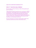
Some routers, such as the Cisco 2505 Router, actually provide the
Ethernet interface in the form of a hub (see Figure 7.6). This negates
the need for a separate hub, and PCs can be plugged directly into the
hub ports available on the router. If more hub ports are required, a
crossover cable can be used to connect one of the hub ports on the
router to a port on an additional hub.
PART II Router Design a nd Bas ic Conf igura tion
CHAPTER 7 Se tting Up a New Router
FIGURE 7.6
The Cisco 2505 provides
one Ethernet interface in
the form of an 8-port
hub.
Hub ports
SEE ALSO
➤ For more information on twisted pair cabling,see page 17.
1 2 1
PART II
Connecting the Router to the Netw ork CHAPTER 7
Serial Connections
Serial connections on the router can be configured for several differ-
ent WAN protocols. The actual physical serial connection on Cisco
routers is a 60-pin female port (see Figure 7.7).
Daisy-chained hubs
If you plan on daisy-chain-
ing (connecting hub-to-hub)
several hubs to an Ethernet
port on a router, remember
that you are limited to four
hub devices in the data
path between Ethernet
devices.
Check your connections
If you’ve physically
connected a particular
interface correctly, you will
typically find that the
router acknowledges the
connection. For example,
connecting a serial
connection from your router
to the appropriate device
will usually register on the
router as the fact that the
particular interface is up,
meaning it is active (even if
an appropriate protocol has
not yet been configured for
the interface).
FIGURE 7.7
The Cisco router 60-pin
serial port connector.
The Cisco 2505 Router (shown in Figure 7.6) supplies two serial
ports. The serial port supports several different signaling standards
including V.35, X.21bis, and EIA-530. Figure 7.8 shows a V.35 cable
that supplies the male 60-pin connector for connection to the
router’s serial port. The other end of the V.35 cable would typically
be placed in a CSU/DSU or other device in WAN connections.
Table 7.2 lists some of the signaling standards supported by Cisco
serial interfaces.
Table 7.2 Serial Signaling Standards
Standard Specification
V.35 Synchronous communications between networks and packet-
switching WANS
X.21bis Defines communications between DTEs and DCEs in an X.25
WAN
EIA-530 RS232 standard for unbalanced serial communications
1 2 2
A Final Word on Physical Router
Connections
Whether you should configure the router before connecting it to the
serial and LAN interfaces that it will service, or connect the router
and then configure it, is pretty much a chicken-or-egg dilemma.
Configuring the router with a very basic configuration so that it can
be seen on the network can allow you to then connect the router to
all its various physical connections and then complete the configura-
tion of the router using a virtual terminal over the network (virtual
terminals are discussed in the next chapter).
If the router can be connected to the various LAN and WAN devices
before you configure the router, this allows you to fully configure
and test the connections immediately. However, if the router is
placed in an area that is somewhat difficult to access (such as a small
closet on a hub rack), it might be difficult to directly connect a PC to
the router for configuration purposes.
Whatever the case, the next chapter discusses how to configure a
new router right out of the box.
PART II Router Design a nd Bas ic Configuration
CHAPTER 7 Se tting Up a New Router
FIGURE 7.8
A V.35 cable provides the
connection between the
router’s serial port and
another device such as a
CSU/DSU.
Buyer beware!
When you acquirethe
cables that you need to
connect your router
interfaces to various serial
connections, make sure
that you purchase the
appropriate pin
configurations. All cables
look alike to the vendors
you call for your
equipment; be very specific
about your cable
specifications.
Basic Router Configuration
Configuring a Router
•
Router Boot Sequence
•
Working with the System
•
Configuration Dialog Box
Using the Different Router Modes
•
8
c h a p t e r
1 2 4
Configuring a Router
Setting up a basic configuration for a router is a matter of enabling
the various interfaces on the router and setting the software settings
for the routed and routing protocols. For example, if you are routing
IP, the interfaces must be assigned appropriate IP addresses. Routing
protocols must also be configured (if you are going to use RIP or
IGRP, you must configure these protocols). And any serial interfaces
that you use must also be configured with an appropriate WAN layer
2 protocol (such as HDLC or Frame Relay). Basic configuration
information may also include bandwidth information and timing
information for WAN connections.
Bottom line—the configuration file for your router uses software set-
tings that tell the router what to route and how to route it. All the
commands that you use to configure the router are part of the Cisco
IOS command set. You will also find that there are several different
ways that you can configure the router, either directly by using the
router console, or by loading a configuration file that has been
placed on a Trivial File Transport Protocol (TFTP) server on your
network. The following list shows some of the possibilities for load-
ing configuration information onto a router:
■ Router Console—You can configure the router directly from a
PC—the router console—that is connected to the router console
port using the rollover cable that comes with the router. The PC
must be running terminal emulation software that allows you to
connect to the router through the PC’s serial port. You also can
connect directly to the router using the router’s auxiliary port,
which is typically housed next to the console port on the back of
the router.
■ Virtual Terminal—If the router has already been provided a
basic configuration that gets at least some of the interfaces up
and running on the network (such as an Ethernet port), you can
Telnet to the router via a virtual terminal. This simply means
that a computer on the network that is running a Telnet pro-
gram can connect to the router and configure the router (if the
appropriate passwords are known—which will be discussed in
more detail later in this chapter).
PART II Router Design a nd Bas ic Configuration
CHAPTER 8 Ba sic Ro uter Configuration
1 2 5
PART II
Configuring a Router CHAPTER 8
■ Network Management Workstation—Routers can also be con-
figured from a workstation on the network that runs special net-
work management software, such as Cisco’s CiscoWorks or a
similar product from Hewlett Packard known as HP OpenView.
■ Cisco ConfigMaker—This graphics-based program (see Figure
8.1) allows you to build a configuration for a router or routers
on a network and then load the configuration to a router that is
directly connected to a router console (the PC that is running
ConfigMaker) or other routers that are connected to the net-
work. Delivering router configurations from ConfigMaker to
routers on the network requires that the network interfaces on
these routers already be configured. ConfigMaker will be dis-
cussed in greater detail in Chapter 16, “Configuring the Router
with Cisco ConfigMaker.”
■ TFTP Server—A configuration for a router can be loaded from a
TFTP server on the network. Saving configurations to a TFTP
server and then downloading them to a particular router is very
straightforward. TFTP servers will be discussed in Chapter 17,
“Using a TFTP Server for Router Configuration Storage.”
FIGURE 8.1
Software such as Cisco’s
ConfigMaker allows you
to diagram your internet-
workand then load your
configurations to a
router or routers.
1 2 6
Of all the configuration methods available, probably the easiest and
the most directly hands-on is configuring the router by directly con-
necting a PC to the router console port (see Figure 8.2). This not
only allows you to quickly set up a basic configuration on the router
using the router System Configuration dialog, but it also allows you
to fine-tune your configuration in the router Configuration mode.
Both of these configuration methods will be discussed in the chapter.
PART II Router Design a nd Bas ic Configuration
CHAPTER 8 Ba sic Ro uter Configuration
FIGURE 8.2
A PC can be directly
connected to a router
using the console or
auxiliary ports.
Console port
Auxiliary port
Before you take a look at how to set up a basic configuration using
the System Configuration dialog on a new router, let’s take a look at
the router boot sequence. This will also give us some insight into
where the router looks for a configuration file when it comes online.
SEE ALSO
➤ For more information about TFTP servers,see page 289.
SEE ALSO
➤ For more information about basic router commands and configuring a router, see page 141.
Router Boot Sequence
You’ve already learned the different memory types found in the
router (such as RAM, NVRAM, Flash RAM, and ROM). And all
these memory types play a part in the boot sequence of a router.
Before you walk through the sequence of steps to configure a brand
new router right out of the box, some discussion is required to
explain the router boot sequence and the various places that the
router will look for a configuration file.
As good as gold
Configuring a routercor-
rectly and appropriately for
the internetwork it serves
is really the most important
aspect of working with
routers (of course, I’m
downplaying internetwork
design and troubleshooting
for the moment). This is
why Cisco Certified
Internetworking Engineers
are highly paid and
respected internetworking
professionals. A proper
configuration really
becomes as important as
gold. You will look at differ-
ent ways of saving (and
protecting) your configura-
tion files as you work
throughthis chapter.
1 2 7
PART II
Router Boot Sequence CHAPTER 8
When you power the router on, the ROM chip runs a Power On Self
Test (POST) that checks the router’s hardware such as the processor,
interfaces, and memory. This test isn’t unlike the power-on test that
a PC runs when you power it on (RAM, CPU, and other hardware
is checked).
The next step in the router boot-up sequence is the execution of a
bootstrap program that is stored in the router’s ROM. This boot-
strap program searches for the CISCO IOS. The IOS can be loaded
from the ROM itself (routers either have a partial or complete copy
of the CISCO IOS in ROM), the router’s FLASH RAM, or from a
TFTP server on the network (commands for loading the IOS from
various locations will be discussed in the next chapter). The IOS is
typically stored in the router’s Flash RAM.
After the router’s IOS is loaded, the router searches for the configu-
ration file. The configuration file is normally held in NVRAM (a
copy command is used to copy a running configuration to NVRAM).
As with the IOS, however, the configuration file can be loaded from
a TFTP server (again, the location of the configuration file would be
dictated by information held in the router’s NVRAM).
After the router loads the configuration file, the information in the
file enables the interfaces and provides parameters related to routed
and routing protocols in force on the router. Figure 8.3 provides a
summary of the router start-up process. Keep in mind that loading
the IOS from a source other than Flash RAM requires a notation in
the ROM’s configuration Registry and that to load the configuration
file from a source other than NVRAM, information pointing to the
location of the file has to be contained in NVRAM.
If a configuration isn’t found in NVRAM or in another place speci-
fied (such as a TFTP server), the Setup mode is entered and the
System Configuration dialog appears on the router console screen.
The next section discusses how to set up a basic router configuration
using the dialog.
SEE ALSO
➤ To review the different memory components on a router, see page 113.
SEE ALSO
➤ For more about the Cisco IOS command set,see page 142.
1 2 8
Working with the System Configuration
Dialog Box
When you boot up a new router (or a router where the configuration
file has been deleted), the System Configuration dialog is loaded (see
Figure 8.4). This Setup mode asks you a series of questions; the
answers to those questions provide a basic configuration for the router.
Working through the Setup dialog is very straightforward. You do
need to know certain parameters related to the configuration of the
router, however, such as which network protocols you will route (IP,
IPX, AppleTalk) and the parameters related to the various interfaces.
For example, if you route IP you will need to know the IP addresses
of the router interfaces that you want to configure (the following
steps provide sample addresses). If you have a router that you want
to configure, follow the steps provided.
PART II Router Design a nd Bas ic Configuration
CHAPTER 8 Ba sic Ro uter Configuration
FIGURE 8.3
The router boot
sequence loads the
router IOS and the router
configuration file.
Configuring a router
from scratch
You can erase the
configuration file for a
router and then start over,
building a new basic con-
figuration using the config-
uration dialog. At the
enable prompt type erase
startup-config, and
then press Enter. This
erases the configuration
file from NVRAM. To restart
the router type reload.
Then press Enter to con-
firm the reload. The router
will reboot and the System
Configuration dialog will
appear onthe Router
Console screen.
1 2 9
PART II
Workin g with the System Configuration Dialo g Bo x CHAPTER 8
SEE ALSO
➤ For more about IP addressing,see page 195.
Starting the Setup Dialog Box
The Setup dialog can ask you quite a few questions related to setting
various passwords for the routers and configuring the interfaces on
the router. The first part of the setup configuration relates to setting
up enable and virtual terminal passwords for the router.
Starting the configuration process with the Setup dialog
1. You will be asked Would you like to enter the initial config-
uration dialog? (see Figure 8.4). Press Enter to answer yes (the
default option) and continue.
2. You will then be asked if you want to see the current interface
summary. This allows you to view the interfaces on the router.
Press Enter to continue. A summary of the interfaces on the
router will be provided as shown in Figure 8.5. Note that the
Ethernet 0 interface is up, but that both the serial interfaces on
this router are down. Also, no IP numbers have been assigned to
the interfaces.
3. Next, you are asked to provide a name for the router. Type a
name (such as ciscokid) and then press Enter.
FIGURE 8.4
The Setup dialog helps
you build a basic config-
uration for a new router
by asking a series of
questions.
IOS version and sup-
ported network protocols
The 2505 router configured
in the figures in the follow-
ing sections is running
Cisco IOS 11.3. This version
of the IOS supports IP, IPX,
AppleTalk, and DECnet
routing. This book will dis-
cuss the routing of IP, IPX,
and AppleTalk, the most
commonly routed network
protocols.
1 3 0
4. The next Setup dialog question asks you to provide an enable
secret password. This password is encrypted and will provide
you with access to the router’s Enable mode (the mode that
allows you to make changes to the router’s configuration). Type
an appropriate password, and then press Enter.
5. You are then asked to provide an “enable” password, which
seems redundant because you have already provided a secret
password for the Enable mode. This second password is related
to earlier versions of the Cisco IOS that didn’t provide the capa-
bility to create an encrypted password for the Enable mode.
Because you aren’t allowed to leave this password blank (even
though you won’t use it), type a value (something you can
remember but isn’t apparent to someone trying to access the
router who shouldn’t). In this case I will use password. Press
Enter to continue.
6. You will then be asked to provide a virtual terminal password for
the router. This password is used by virtual terminals that Telnet
to the router over the network. This enables you to monitor
(and even configure a router) from a remote workstation on the
network. Provide a virtual terminal password, and press Enter
to continue.
7. The next Setup dialog question asks you if you want to enable
SNMP (Simple Network Management Protocol). This protocol pro-
vides baselines for network operations and provides a way to
monitor changes in the network using a management station
(which requires software such as CiscoWorks). If you won’t use
management software to manage the routers, there is no reason
to enable SNMP). In this case you won’t enable it. Type no at
the prompt and press Enter to continue.
PART II Router Design a nd Bas ic Configuration
CHAPTER 8 Ba sic Ro uter Configuration
FIGURE 8.5
The Setup dialog pro-
videsa summary of the
physical interfaces on
the router.
1 3 1
PART II
Workin g with the System Configuration Dialo g Box CHAPTER 8
Configuring Routed Protocols
The next portion of the Setup dialog is related to the configuration
of routed and routing protocols that will be used on the router. You
will be asked if you want to enable each of the routed protocols sup-
ported by your version of the IOS and to choose which routing pro-
tocols you want to enable.
Configuring protocols with the Setup dialog
1. In the case of the 2505 router that you are configuring, the next
prompt asks if DECnet should be enabled (DECnet is a protocol
stack supported by the Digital Equipment Corporation). The
default response is No. Press Enter to continue.
2. In the case of our 2505 router, the next dialog prompt asks if
AppleTalk should be configured. For now, you will respond with
no (the default). Chapter 13, “Routing AppleTalk,” covers the
ins and outs of AppleTalk routing and I’ll defer AppleTalk until
then. Press Enter to continue.
3. The next dialog prompt asks if IPX should be configured (IPX is
covered in detail in Chapter 12, “Routing Novell IPX,”). To
answer no, press Enter.
4. The next prompt asks if IP should be configured and the default
answer is Yes (see Figure 8.6). Although IP will be covered in
great detail in Chapters 10, “TCP/IP Primer,” and 11,
“Configuring IP Routing,” it makes sense to enable IP at this
point. This enables you to get the router up and running on the
network, and then you can further configure the router using a
virtual terminal or by loading a ready-made configuration file
from Cisco ConfigMaker or a TFTP server. Press Enter (to say
yes) and continue.
5. You will then be asked if you want to configure IGRP on the
router. IGRP is one of the IP routing protocols. Configuring
IGRP and RIP will be covered in Chapter 11, so for the moment
you can say no. Type no and press Enter to continue.
6. You will then be asked to configure RIP. No is the default, so
press Enter to continue.
7. The next dialog asks if bridging should be enabled on the router.
Press Enter to continue (No is the default).
1 3 2
Configuring Router Interfaces
The next part of the Setup dialog is related to the configuration of
the router’s interfaces. You will be asked which router interfaces will
be in use on the router (such as Ethernet and serial interfaces). Also,
because IP was enabled for routing, you will have to supply IP
addresses for the various interfaces on the router. How these IP
addresses were arrived at will be discussed in Chapter 10.
Configuring interfaces with the Setup dialog
1. The next prompt relates to the first interface on the router,
which in the case of the 2505 router is the Ethernet 0 interface.
You will be asked if this interface is in use. Yes is the default
value, so to enable the interface, press Enter.
2. The next prompt asks if IP should be configured on the interface
(E0). The default value is Yes; press Enter to continue.
3. The next prompt asks for the IP address of the interface (inter-
faces on the router use IP addresses just like any other node on
the network). Type 10.16.1.1 as the address for the E0 interface
(see Figure 8.7). Then press Enter to continue.
4. The next prompt asks how many bits are in the subnet field.
This number relates to how many IP subnets have been created
for your internetwork. This will be discussed in Chapter 10. For
now, trust that I’ve divided the available network addresses
(which are class A addresses) into 14 subnets, which requires 4
bits in the subnet field (this will make sense after you read
Chapter 10). Type 4 and then press Enter.
PART II Router Design a nd Bas ic Config ura tion
CHAPTER 8 Ba sic Ro uter Configuration
FIGURE 8.6
Enabling IP allows you to
get the router up and
running on the network
for further configuration.
1 3 3
PART II
Workin g with the System Configuration Dialo g Box CHAPTER 8
FIGURE 8.7
An IP address is
assigned to the Ethernet
0 port on the router.
5. Because the 2505 router’s E0 interface is actually an eight-port
hub, you are asked if you want to enable all ports on the hub.
The default is Yes (and you want to say yes), so press Enter to
continue.
6. You are then asked if you want to configure the next interface on
the router, which in this case is serial 0. Yes is the default. Press
Enter to continue.
7. You are then asked if you want to configure IP on the S0 inter-
face. Press Enter and continue.
8. You are given the option of configuring the S0 interface as IP
unnumbered (this means that the interface will route IP but
doesn’t require its own IP number). This is done to actually save
your IP addresses (from the pool of IP addresses that you have
available). Configuring serial interfaces with IP addresses will be
handled in more detail in Chapter 11. For now, press Enter to
say no.
9. You are then asked to provide an IP address for the S0 interface.
Type 10.32.1.1. Then press Enter.
10. You will then be asked to provide the subnet field bits. This is
defaulted to 4, which was entered in step 4. Press Enter to use
the same bit count.
11. You are now asked to configure the Serial 1 interface. Press
Enter to say yes.
12. Press Enter to say no to IP unnumbered.
13. Type the IP address 10.48.1.1 at the prompt (see Figure 8.8).
Then press Enter.