Tony Bourke Server Load Balancing phần 3 docx
Bạn đang xem bản rút gọn của tài liệu. Xem và tải ngay bản đầy đủ của tài liệu tại đây (359.88 KB, 19 trang )
Other SLB Methods
29
Internet User
208.185.43.202
Web Server
IP: 192.168.0.100
Loopback alias: 192.168.0.200
MAC: 00:00:00:00:00:bb
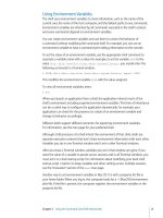
Figure 3-4.
The DSR
traffic
path
complexity to a configuration, and added complexity can make a network archi-
tecture more difficult to implement. Also, any Layer 5-7 URL parsing or hashing
would not work because that process requires a synchronous data path in and out
of the load balancer. Cookie-based persistence would not work in most situations,
although it is possible.
Other SLB Methods
There are several other ways to perform network-based SLB. The way it is nor-
mally implemented is sometimes called "half-NAT," since either the source address
or the destination address of a packet is rewritten, but not both. A method known
as "full-NAT" also exists. Full-NAT rewrites the source and destination addresses at
the same time. A given scenario might look like the one in Table 3-3.
Table 3-3. Full-NAT SLB
Step
1
2
3
4
Source
208.185.43.202
10.0.0.1
10.0.0.100
192.168.0.200
Destination
192.168.0.200
10.0.0.100
10.0.0.1
208.185.43.202
In this situation, all source addresses, regardless of where the requests come from,
are set to one IP address. The downside to this is that full-NAT renders web logs
30 Chapter 3: Anatomy of a Server Load Balancer
useless, since all traffic from the web server's point of view comes from one IP
address.
A situation like this has limited uses in SLB and won't be discussed beyond this
chapter. It can sometimes be useful for features such as proxy serving and cache
serving, but for SLB, full-NAT is not generally used.
Under the Hood
SLB devices usually take one of two basic incarnations: the switch-based load bal-
ancer or the server-based load balancer. Each has its general advantages and
drawbacks, but these greatly depend on how the vendor has implemented the
technology.
Server-Based Load Balancers
Server-based load balancers are usually PC-based units running a standard oper-
ating system. Cisco's LocalDirector and F5's BIG-IP are both examples of server-
based load balancers. SLB functions are performed by software code running on
top of the network stack of the server's OS. Generally, the OS is an OEMed ver-
sion of a commercial OS such as BSDI or a modified freeware OS such as Linux or
FreeBSD. In a load balancer such as Cisco's LocalDirector, the entire OS is written
by the manufacturer.
Server-based load balancers are typically easy to develop for because the coding
resources for a widely used OS are easy to come by. This can help shorten code
and new-feature turnaround, but it can also be a hindrance. With shorter code
cycles, bugs can become more prevalent. This easy development cycle means that
sever-based load balancers are typically flexible in what they can do. New fea-
tures can be rolled out swiftly, and the machines themselves can take on new and
creative ways of performance monitoring, as well as other tasks.
Switch-Based Load Balancers
Switch-based load balancers, also known as hardware-based load balancers, are
devices that rely on Application Specific Integrated Circuit (ASIC) chips to perform
the packet-rewriting functions. ASIC chips are much more specialized processors
than their Pentium or PowerPC cousins. Pentium and PowerPC chips have a gen-
eral instruction set to them, which enables a wide variety of software to be run,
such as Quake III or Microsoft Word. An ASIC chip is a processor that removes
several layers of abstraction from a task. Because of this specialization, ASIC chips
often perform software tasks much faster and more efficiently than a general pro-
cessor. The drawback to this is that the chips are very inflexible. If a new task is
Under the Hood
31
needed, then a new ASIC design may have to be built. However, the IP protocol
has remained unchanged, so it's possible to burn those functions into an ASIC.
The Alteon and Cisco CSS lines of load-balancing switches, as well as Foundry's
Serverlron series, are all examples of switch-based load balancers featured in this
book.
Switch-based load balancers are typically more difficult to develop code for. They
often run on proprietary architectures, or at least architectures with minimal devel-
opment resources. Therefore, code comes out slower but is more stable.
The switch-based products are also usually faster. Their ASIC chips are more effi-
cient than software alone. Typically, they also have internal-bandwidth backbones
capable of handling a Gbps worth of traffic. PCs are geared more toward general
I/O traffic and are not optimized for IP or packet traffic.
It All Depends
Again, it needs to be said that while there are certain trends in characteristics of
the two main types of architectures, they do not necessarily hold true in every
case. Performance, features, and stability are issues that can vary greatly from
vendor to vendor. Therefore, it would be unfair to state that any given switch-
based load balancer is a better performer than a PC-based load balancer, or that
any PC-based load balancer has more features than a switch-based load balancer.
Performance Metrics
In this chapter, I will discuss the many facets of performance associated with SLB
devices. There are many different ways to measure performance in SLB devices,
and each metric has a different level of importance depending on the specific
needs of a site. The metrics discussed in this chapter include:
• Connections per second
• Total concurrent connections
• Throughput (in bits per second)
Performance metrics are critical because they gauge the limit of your site's imple-
mentation.
Connections Per Second
As far as pure performance goes, this is probably the most important metric, espe-
cially with HTTP. Connections per second relates to the number of incoming con-
nections an SLB device accepts in a given second. This is sometimes referred to as
transactions per second or sessions per second, depending on the vendor. It is
usually the limiting factor on any device, the first of any of the metrics to hit a per-
formance limit. The reason this metric is so critical is that opening and closing
HTTP connections is very burdensome on a network stack or network processor.
Lets take a simplified look at the steps necessary to transfer one file via HTTP:
1. The client box initiates an HTTP connection by sending a TCP SYN packet
destined for port 80 to the web server.
2. The web server sends an ACK packet back to the client along with an addi-
tional SYN packet.
3. The client sends back an ACK packet in response to the server's SYN request.
32
4
Throughput 33
The beginning of a connection is known as the "three-way handshake." After the
handshake is negotiated, data can pass back and forth. In the case of HTTP, this is
usually a web page.
Now this process has quite a few steps for sending only 30 KB worth of data, and
it strains a network device's resources. Setting up and tearing down connections is
resource-intensive. This is why the rate at which a device can accomplish this is so
critical.
If you have a site that generates a heavy amount of HTTP traffic in particular, this
is probably the most important metric you should look for when shopping for an
SLB
device.
Total Concurrent Connections
Total concurrent connections is the metric for determining how many open TCP
user sessions an SLB device can support. Usually, this number is limited by the
available memory in an SLB device's kernel or network processor. The number
ranges from infinity to only a few thousand, depending on the product. Most of
the time, however, the limit is theoretical, and you would most likely hit another
performance barrier before encountering the total available session number.
For UDP traffic, concurrent connections are not a factor, as UDP is a completely
connectionless protocol. UDP traffic is typically associated with either streaming
media or DNS traffic, although there are several other protocols that run on UDP.
Most load balancers are capable of handling UDP protocols for SLB.
Throughput
Throughput is another important metric. Typically measured in bits per second,
throughput is the rate at which an SLB device is able to pass traffic through its
internal infrastructure. All devices have internal limiting factors based on architec-
tural design, so it's important to know the throughput when looking for an SLB
vendor. For instance, a few SLB vendors only support Fast Ethernet, thus limiting
them to 100 Mbps (Megabits per second). In addition, some server-based products
may not have processors and/or code fast enough to handle transfer rates over 80
Mbps.
While throughput is measured in bits per second, it is actually a combination of
two different variables: packet size and packets per second. Ethernet packets vary
in length, with a typical Maximum Transmittable Unit (MTU) of about 1.5 KB. If a
particular piece of data is larger than 1.5 KB, then it is chopped up into 1.5 KB
chunks for transport. The number of packets per second is really the most impor-
tant factor a load balancer or any network device uses. The combination of this
34 Chapter 4: Performance Metrics
and packet size determines the bits per second. For example, an HTTP GET on a
100-byte text file will fit into one packet very easily. An HTTP GET on a 32 KB
image file will result in the file being chopped into about 21 Ethernet packets, but
each would have a full 1.5 KB payload. The bigger the payload, the more efficient
use of resources. This is one of the main reasons why connections per second is
such an important metric. Not only do connections per second cause quite a bit of
overhead on just the initiation of a connection, but sites that experience high rates
of connections per second typically have small payloads. Throughput can be cal-
culated as follows:
Throughput = packet transmission rate x payload size
The 100 Mbps Barrier
As stated before, many SLB models are equipped with only Fast Ethernet inter-
faces, thus limiting the total throughput to 100 Mbps. While most users aren't nec-
essarily concerned with pushing hundreds of Megs worth of traffic, many are
concerned that while they push 50 Mbps today, they should be able to push 105
Mbps in the future.
To get around this, there are a couple of techniques available. One technique
involves Fast EtherChannel, which binds two or more Fast Ethernet links into one
link, combining the available bandwidth. This isn't the simplest solution by far,
and there are limits to how Fast EtherChannel distributes traffic, such as when one
portion of the link is flooded while another link is unused.
Another solution is the Direct Server Return (DSR) technology discussed in Chap-
ters 2 and 3. Since DSR does not involve the outbound traffic passing the SLB
device, which is typically the majority of a site's traffic, the throughput require-
ments of an SLB device are far less. At that point, the limiting factor would
become the overall connectivity of the site.
The simplest solution to this problem is using Gigabit Ethernet (GigE) on the load
balancers. The costs of GigE are dropping to more affordable levels, and it's a
great way to aggregate large amounts of traffic to Fast Ethernet-connected servers.
Since the limit is 1 Gbps (Gigabit per second), there is plenty of room to grow a
90 Mbps site into a 190 Mbps site and beyond. Getting beyond 1 Gbps is a chal-
lenge that future SLB products will face.
Traffic Profiles
Each site's traffic characteristics are different, but there are some patterns and simi-
larities that many sites do share. There are three typical traffic patterns that I have
identified and will go over in this section. HTTP, FTP/Streaming, and web store
Traffic Profiles
35
traffic seem to be fairly typical as far as traffic patterns go. Table 4-1 lists these pat-
terns and their accompanying metrics. Of course, the traffic pattern for your site
may be much different. It is critical to identify the type or types of traffic your sites
generate to better design your site, secure your site, and tune its performance.
Table 4-1. The metrics matrix
Traffic pattern
HTTP
FTP/Streaming
Web store
Most important
metric
Connections per
second
Throughput
Total sustained
connections
Second most
important metric
Throughput
Total sustained
connections
Connections per
second
Least important metric
Total sustained
connections
Connections per second
Throughput
HTTP
HTTP traffic is generally bandwidth-intensive, though it generates a large amount
of connections per second. With HTTP 1.0, a TCP connection is opened for every
object, whether it be an HTML file, an image file (such as a GIF or JPEG), or text
file. A web page with 10 objects on it would require 10 separate TCP connections
to complete. The HTTP 1.1 standard makes things a little more efficient by making
one connection to retrieve several objects during a given session. Those 10 objects
on the example page would be downloaded in one continuous TCP connection,
greatly reducing the work the load balancer and web server would need to do.
HTTP is still fairly inefficient as far as protocols go, however. Web pages and their
objects are typically kept small to keep download times small, usually with a 56K
modem user in mind (a user will likely leave your site if the downloads take too
long). So web pages generally don't contain much more than 70 or 80 KB worth
of data in them. Now, that number greatly varies depending on the site, but it is
still a relatively small amount of data.
FTP/Streaming
FTP and streaming traffic are very similar in their effects on networks. Both involve
one initial connection (or in the case of streaming, which often employs UDP, no
connection) and a large amount of data transferred. The rate of FTP/streaming ini-
tial connections will always remain relatively small compared to the amount of
data transferred. One FTP connection could easily involve a download of a Mega-
byte or more worth of data. This can saturate networks, and the 100 Mbps limit is
usually the one to watch.
36 Chapter 4: Performance Metrics
Web Stores
Web stores are where the money is made on a site. This is the money that usually
pays the bills for the network equipment, load balancers, and salaries (and also
this book!), so this traffic must be handled with special care. Speed is of the
utmost importance for this type of traffic; users are less likely to spend money on
sites that
are too
slow
for
them. This type
of
traffic
does
not
generally involve
a
large amount of bandwidth, nor does it involve a large amount of connections per
second (unless there is a media-related event, such as a TV commercial). Sus-
tained connections are important, though, considering that a site wants to support
as many customers as possible,
Stateful redundancy
One critical feature to this type of profile, as opposed to the others, is the redun-
dancy information kept between load balancers. This is known as stateful redun-
dancy. Any TCP session and persistence data that one load balancer has, the other
should have to minimize the impact of a fail-over, which is typically not a con-
cern of noninteractive sites that are largely static. Cookie table information and/or
TCP sessions need to be mirrored to accomplish this. Other profiles may not
require this level of redundancy, but web stores usually do.
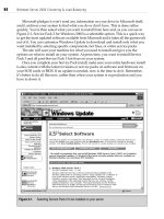
The Wall
When dealing with performance on any load-balancing device, there is a concept
that I refer to as "the wall." The wall is a point where the amount of traffic being
processed is high enough to cause severe performance degradation. Response
time and performance remain fairly constant as traffic increases until the wall is
reached, but when that happens, the effect is dramatic. In most cases, hitting the
wall means slower HTTP response times and a leveling out of traffic. In extreme
cases, such as an incredibly high amount of traffic, there can be unpredictable and
strange behavior. This can include reboots, lock-ups (which do not allow the
redundant unit to become the master), and kernel panics. Figure 4-1 shows the
sharp curve that occurs when the performance wall is hit.
Additional Features
Of course, as you add features and capabilities to a load balancer, it is very likely
that its performance may suffer. It all depends on how the load balancer is
designed and the features that you are employing.
Load balancers don't generally respond any slower as you add features. However,
adding features will most likely lower the upper limit of performance degradation.
The Wall
37
Traffic
Figure 4-1. The performance barrier
For instance, if a load balancer can push 90 Mbps and no latency with just Layer 4
running, it may be able to push only 45 Mbps with URL parsing and cookie-based
persistence enabled. The reason is that in Layer 5-7, much more (or even all) of
the packet must be inspected. Doing this can be very CPU-intensive. Whether
parsing the URL or reading the cookie in the packet, it's much more than just
rewriting the IP header info.
Switch-based versus server-based performance degradation
The amount of performance degradation observed with the addition of function-
ality also greatly depends on the way the load balancer is engineered. In
Chapter 3, I went over the differences between switch-based and server-based
load balancers.
With server-based load balancers, this degradation is very linear as you add func-
tions. The more the processor has to do, the lower the amount of traffic a load
balancer can process with acceptable speed.
With switch-based load balancers, this is not necessarily the case. ASIC chips are
employed to handle the network processing. Some vendors have developed ASIC
chips to handle the functions of Layer 5 processing, resulting in a more distrib-
uted architecture with some components handling Layer 4, others handling Layer
5, and so on. Other switch-based vendors rely on ASICs for their Layer 4 functions
and a general processor for the Layer 5-7 functions. The performance characteris-
tics of each of these components can vary greatly.
The Alteon series of load balancers, for example, have dedicated pairs of proces-
sors for each port on their switches. Each set of processors has a CPU and
memory, and is capable of independent handling of the traffic associated with that
particular port. The Alteon 8.0 series and later also has a feature called Virtual
38 Chapter 4: Performance Metrics
Matrix Architecture (VMA), which distributes network load to all the processors on
a switch, even if they don't have traffic flowing through them.
In the end, it depends quite a bit on how a load balancer is coded and designed,
and the features that it uses. These characteristics change from vendor to vendor
and usually from model to model. It's important to know the type of traffic you
are likely to run through the load balancer to understand how to plan for perfor-
mance and potential growth needs.
Practice
and Implementation
of Server Load Balancing
II
Introduction
to Architecture
Ask any hardcore networking gurus about network design, and they'll tell you that
it is an art—and they are absolutely right. This chapter is an introduction to both
the form and the function of a given network infrastructure with SLB. Like all engi-
neering endeavors, there is a difference between adequacy and excellence, and
that difference is often subtle.
When designing your SLB implementation, or any other network implementation,
you should keep in mind the same design aspects that you would with any other
engineering task. Such aspects include:
• Simplicity
• Functionality
• Elegance
Inversely, you should avoid several aspects:
• Complexity
• Fanciness
• Irrelevance
You are looking for the best, easiest, most elegant, and most cost-effective way to
meet all of your requirements. Whether the requirements are spanning a river, a
transatlantic flight, or SLB, the process is the same. When looking for a solution to
fulfill
all of a
site's engineering requirements, always look
for the
simplest solu-
tion available.
One of the worst traps I see network designers fall into is trying to be fancy. They
might think they are being clever by using a specific feature where it needn't be
used, or a special configuration that garners little or no additional functionality.
41
5
42
Chapter 5: Introduction to Architecture
They might revel in their own glory, but that's where the glory stops. Often, con-
figurations like that become overly complex and unmanageable. When it comes
down to crunch time, it's the least-complicated installation that survives.
Why do something in a convoluted manner when you can do it in an easy
manner? Why include something that has no connection to what you are trying to
accomplish? A colorful bow on a load balancer would merely be pretty, while
color-coded Cat 5 cabling with a color-denoting function would be both aestheti-
cally pleasing and extremely useful. Why throw a bunch of components together
with no forethought of their interaction when you can compile the components in
a logical and ordered way? You could go out and buy a router, a Layer 2/3 switch,
and a load balancer, hook them all together and realize you probably didn't need
a router when you have a Layer 2/3 switch (a switch that includes router function-
ality). Always keep in mind the age-old engineering adage of KISS: Keep It Simple
Stupid!
Keeping it simple and elegant will reap untold benefits for your configuration. It
will lower your costs by reducing the amount of necessary equipment. It will sim-
plify maintenance because a simple site is much easier to upkeep than a complex
installation. It will also come in handy during a crisis situation, simplifying the
troubleshooting that needs to be done.
Architectural Details
Most of the people with whom I've spoken say that the most confusing parts of
understanding SLB aren't the concepts or functions. The most confusing part of
SLB is how load balancers fit into a given network infrastructure. There are sev-
eral different ways to implement SLB units in a given network infrastructure, with
many vendors supporting different methods. This can seem quite confusing, but all
of the different ways SLB can be configured in a network can be boiled down to
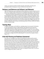
those shown in in Figure 5-1.
Figure 5-1. An SLB implementation matrix
Architectural Details
43
The first column represents the layout of the IP topology. For flat-based SLB, the
VIPs and real servers are on the same subnet. For NAT-based SLB, the VIPs and
the real servers are on separate subnets. The second column represents how the
traffic is directed to the load balancers on the way from the server to the Internet.
Bridge-path means the load balancer is acting as a bridge, being in the Layer 2
path of outbound traffic. Route-path means the load balancer is acting as a router,
being in the Layer 3 path of outbound traffic. Direct Server Return (DSR) is when
the servers are specially configured to bypass the load balancer completely on the
way
out.
Virtually every load-balancing implementation can be classified by using one char-
acteristic from each column. Most load-balancing products support several of the
possible configurations, which can become quite confusing. This matrix greatly
simplifies categorizing a given installation or planned installation. However, not all
combinations are possible, as shown in Figure 5-1. Some don't make any sense
from an architectural standpoint, and some just aren't feasible.
IP Address Configuration:
Flat-Based SLB Versus NAT-Based SLB
These two concepts will be the basis for the next two chapters, as well as the
basis for configuration strategies involving some of the different load balancers dis-
cussed in later chapters. Each way has its own advantages and strengths, and a
site's particular requirements will be the determining factor for which to use.
As you can see with the flat-based SLB architecture shown in Figure 5-2, VIPs and
nodes are on the same subnets. This can be done with either a bridging-path or
route-path SLB method.
Figure 5-2. Flat-based SLB architecture
With the NAT-based SLB architecture shown in Figure 5-3, the load balancer sits
on two separate subnets and usually two different VLANs. The load balancer is the
default gateway of the real servers, and therefore employs the route-path SLB
method. Bridging-path SLB will not work with NAT-based SLB.
44
Chapter 5: Introduction to Architecture
Figure 5-3. NAT-based SLB architecture
Return
Traffic
Management:
Bridging-Path Versus Routing-Path Versus DSR
Most of the configurations I discuss will use route-path SLB rather than bridging-
path. There are a number of reasons for this, first and foremost being that route-
path is typically simpler to implement. In conjunction with the one-armed or two-
armed physical connectivity, any inherent topology and redundancy issues are
much easier to resolve. Bridging-path SLB works only with a flat-based SLB imple-
mentation, while route-path SLB works with either flat-based or NAT-based SLB.
With bridging-path SLB, you run into some deployment limitations. Since bridging-
path SLB works on the Layer 2 level, there can be only one Layer 2 path on which
traffic flows, thus limiting your load-balancer installation to one redundant pair
(one does not forward Layer 2 traffic as a standby unit). If there is more than one
pair, there is more than one Layer 2 path, resulting in either a bridging loop (very
bad) or Layer 2 devices on the network shutting off one or more of the load-bal-
ancer ports.
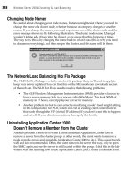
In Figure 5-4, you can see how bridging works with SLB. The load balancer acts as
a Layer 2 bridge between two separate LANs. The packets must traverse the load
balancer in and on their ways out.
Figure 5-4. Bridging-path SLB architecture
With route-path SLB (shown in Figure 5-5), the load balancer is the default route
of the real servers. It works like a router by forwarding packets.
Architectural Details
45
Figure 5-5. NAT-based, route-path SLB architecture
One-Armed Versus Two-Armed
There are a number of possible configurations with flat-based and NAT-based SLB
architectures. However, in this book, one-armed is used only with flat-based SLB
and two-armed, only with NAT-based SLB. There are a number of reasons for this.
With flat-based, using a one-armed method means using the route-path method.
With NAT-based SLB, security is better served by using two separate VLANs for the
outside and internal networks.
With a one-armed configuration (shown in Figure 5-6), there is only one connec-
tion from the load balancer to the network infrastructure. This is perfect for flat-
based SLB, since it involves real servers and VIPs on the same subnet and LAN.
With NAT-based SLB, it is possible to have both the outside and internal networks
on the same link, but that creates a security hazard and, thus, should be avoided.
Figure 5-6. One-armed SLB configuration
With a two-armed configuration (shown in Figure 5-7), two separate links connect
to two separate VLANs on two different subnets. This is the perfect configuration
for NAT-based SLB, as it provides two links on separate networks. This also works
great when using NAT-based SLB as part of a security scheme.
46
Chapter 5: Introduction to Architecture
Figure 5-7. Two-armed SLB configuration
Two-armed is also used for bridge-path topologies, since the load balancer bridges
two separate LANs. It isn't possible to achieve a one-armed configuation with
bridge-path, since the load balancer bridges between two separate LANs.
Infrastructure
Infrastructure deals with how the load balancers and other components are con-
nected to the outside world. There are a variety of possible infrastructure sce-
narios, such as ISPs, colocation data centers, in-house hosting off of leased lines,
and many more. Infrastructure's primary purpose is to provide connectivity to the
outside world and to the Internet. In addition, it often tries to provide a measure
of redundancy in case any device or network link fails. Capacity is also an issue
with infrastructure, as it tries to assure that there will be enough bandwidth avail-
able to service any need.
For any networked infrastructure to work, it needs to have two basic components:
Layer 3 connectivity and Layer 2 aggregation. A Layer 3 router (or a pair for redun-
dancy) is needed to home the network, and from which provide the IP connec-
tivity, to the Internet and the outside world. There is also a Layer 2 infrastructure
that aggregates this IP traffic through Ethernet, connecting the servers, load bal-
ancers, routers, and so on. In most infrastructure situations, there is redundancy
for the Layer 2 and Layer 3 portions as well.
There are several ways in which to build an Internet-connectivity infrastructure.
The following sections discuss a few of the more popular scenarios you may
Infrastructure
47
encounter when dealing with SLB, which is usually in some sort of hosting or
colocation center. This is significant because how the infrastructure is designed
affects how a load balancer is connected to a network and how the load bal-
ancer's redundancy scheme is implemented.
Four Pack
When a site has it's own dedicated routers and switches, a simple setup known as
a "four pack" is commonly used (see Figure 5-8). It's called the four pack because
it utilizes four network devices in a redundant configuration: two switches and two
routers.
Figure 5-8. Four-pack design
Each switch is connected to a router to provide redundancy. VRRP or a similar
Layer 3 redundancy protocol (such as Cisco's HSRP) runs between the two routers
over the trunk link between the two switches. With a trunk between the two
switches, it doesn't matter to which switch a device is connected, as it will still
have connectivity (see Figure 5-9).
This scenario can suffer the failure of any one component. With VRRP running
between the routers, if sw-1 were to die with r-1 as the active router, then r-2
would no longer be able to get to r-1. Since the health-check packets would not
be answered, r-2 would become active and traffic would flow through sw-2.
The most common architectural error in the planning/design phase of a network
occurs in how Layer 3 devices connect to Layer 2 devices (see Figure 5-10). When
diagramming networks, designers have tendencies to interconnect as many devices
48
Chapter 5: Introduction to Architecture
Figure 5-9, Four-pack flow
as possible, such as routers and switches. r-1 would have a link to both sw-1 and
sw-2, and r-2 would have a link to sw-1 and sw-2 so as to provide added redun-
dancy. Unfortunately, there aren't many routers that provide multiple Layer 2 ports
on given interfaces.
Figure 5-10. Four pack with cross-connects
While it is a good idea to cross-connect, it's often not possible.
Six Pack
If a network installation is housed at a colocation-style data center, chances are
that you are connecting into its switch-router infrastructure. If this is the case,